The aim of this studio was to explore the design opportunities arising from three common digital fabrication processes: Laser Cutting, CNC milling and 3D Printing. These exercises were supported by an interactive exploration of each technology and material, while also understanding conceptual and prototyping process of design.
1. Laser Cutting
The first digital fabrication exercise was Laser Cutting, supported by a light station.
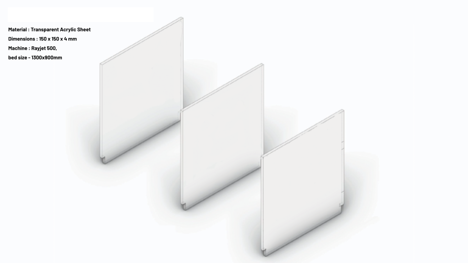
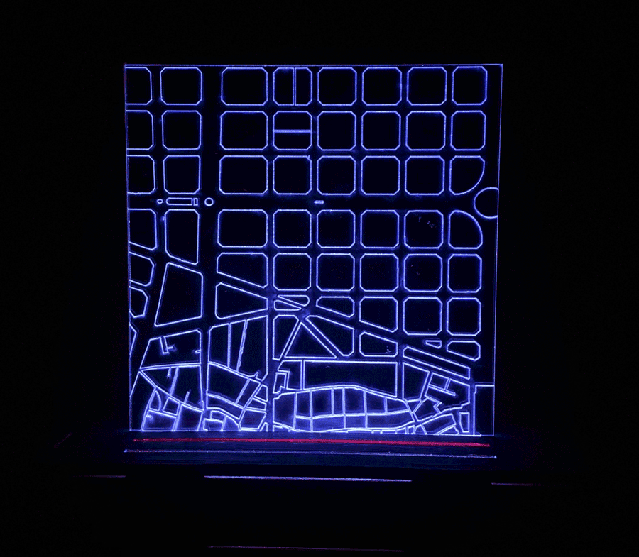
A 4 mm thick acrylic of 150 by 150 mm was laser cut for this exercise. Since light would be passed through it, transparent acrylic has been used.
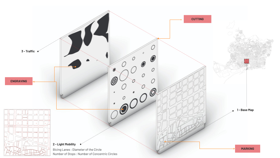
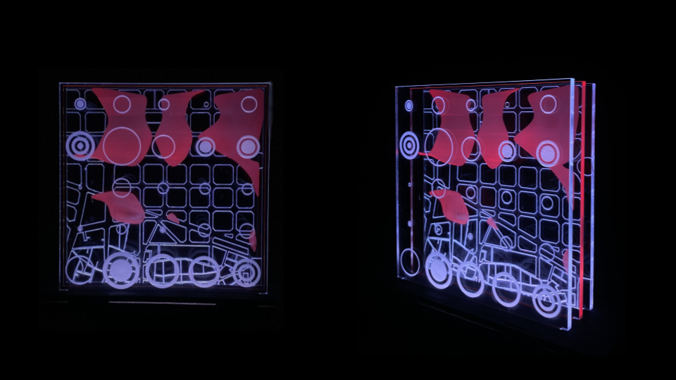
Through this exercise, different datasets of barcelona have been overlapped to understand the relationship between traffic and micro mobility in the city. The first layer being the base map followed by the layer of bicing dataset, where the diameter of the circle is directly proportional to the length of cyclable lanes in that area and the number of concentric circles represent the number of bicing stops. These layers were then overlapped with the third layer of traffic to understand the relation between the two. The base map was marked on the acrylic sheet and the other two layers had engraving as we wanted them to be solid filled for higher visibility when put together.
Once the layers were lasercut, it was time for the second part of this exercise. To illuminate the sheets, RGB Led strips of 12 volt were used. All the channels of RGB were used to get the color white for two strips, and just the red channel for the middle one. Laser Cut separators were then used to stop the lighting from merging into one another.
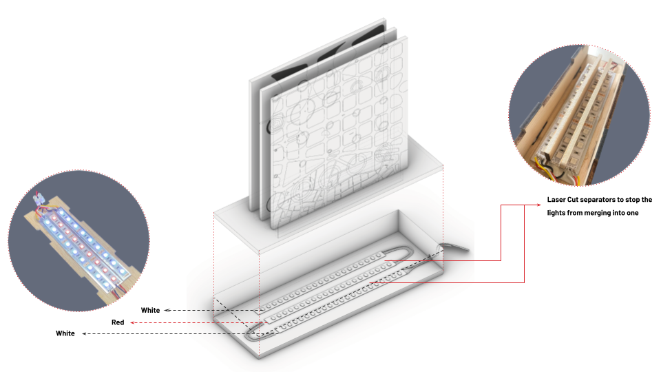
Image Gallery
2. CNC Milling
The second exercise was to understand Fabrication strategies with Subtractive Manufacturing.
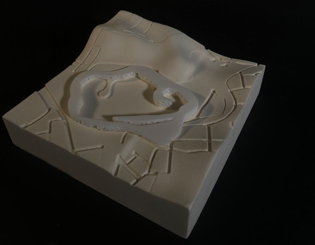
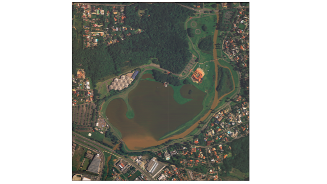
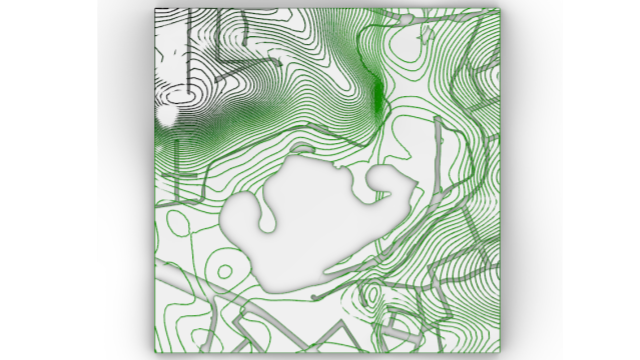
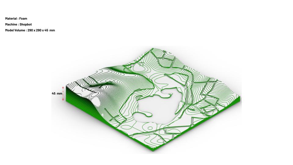
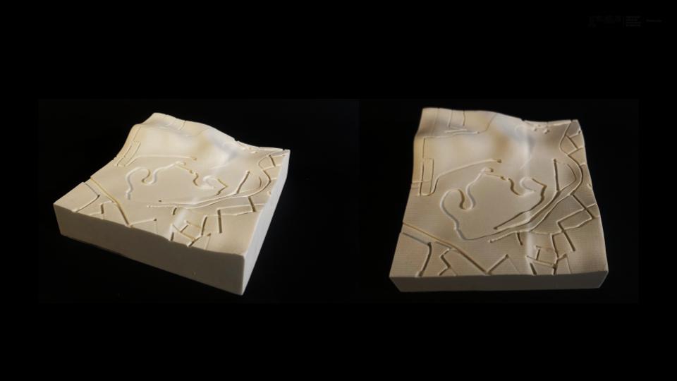
A terrain had to be CNC Milled. Parque Barigui from the city of Curitiba, Brazil was chosen as the site by our group. The site is interesting as it has water, roads, vegetation and buildings, which allowed us to experiment with CNC methods.
We worked with the stock of 300 by 300 and a thickness of 100 mm. Out of which, our model was 290 by 290 with a height of 45 mm.
Production Calculations
Rhino Cam was setup to export the G code for the shopbot machine to execute the milling. A foam piece was cut using 5 layers of techniques. First one being Axis pocketing using a 10 mm flat mill. The reason for why the corners had to be pocketed is because the piece was too deep and the machine would hit the corner wall while cutting some parts, hence it had to be removed. Followed by horizontal roughting with a 10 mm flatmill. Roughing was the first step towards the terrain. Parallel finishing was then done with a 6mm ball mill. Finishing was what made it smooth. A 4 mm flat mill was then used for pocketing. This technique was used to get the streets and the rivers. The process was finished with a 6mm flat mill for axis profiling to get the piece out.

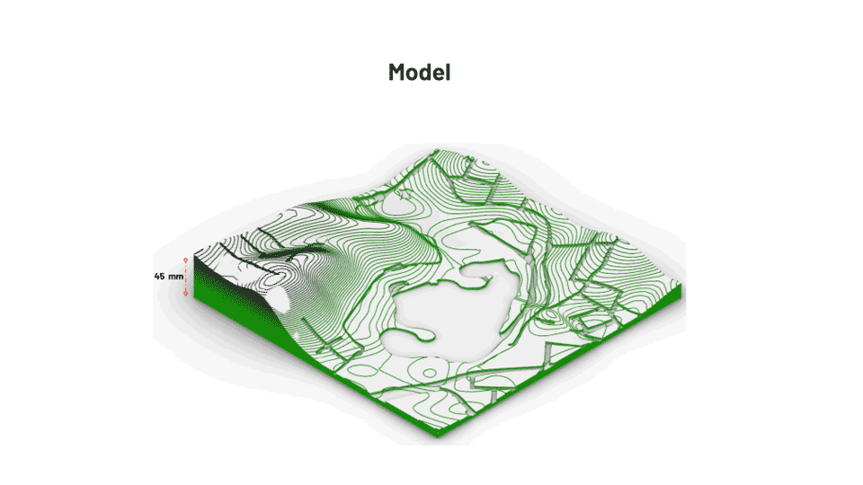
Image Gallery
3. 3D Printing
The third exercise was to 3D print a model to be integrated into the CNC milled terrain.
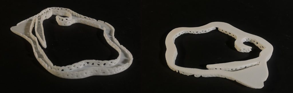
A bridge connecting two opposite major axis of the area was to be 3d printed. The workpiece model was 150 by 190 with a height of 12 mm. The model had a flat top with the walls made of voronoi cells to be placed on the terrain.
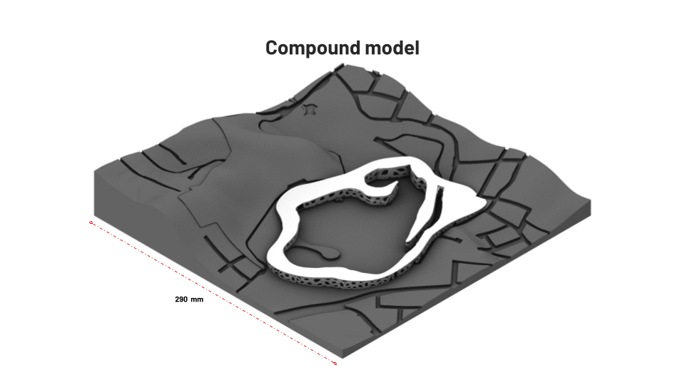
To optimise time and material, we rotated the model for slicing to get a flat base. We used Z suite to slice the model. The machine printed the model using a 0.4 mm diameter nozzle. The infill density is 20 percent and no supports were required to print the model.
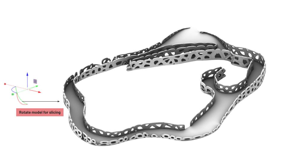

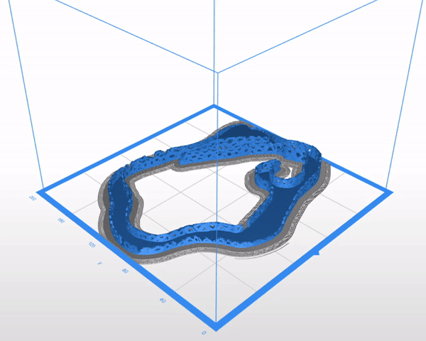
Image Gallery
4. Video Mapping
The final exercise was to integrate the prototype with projection video mapping.