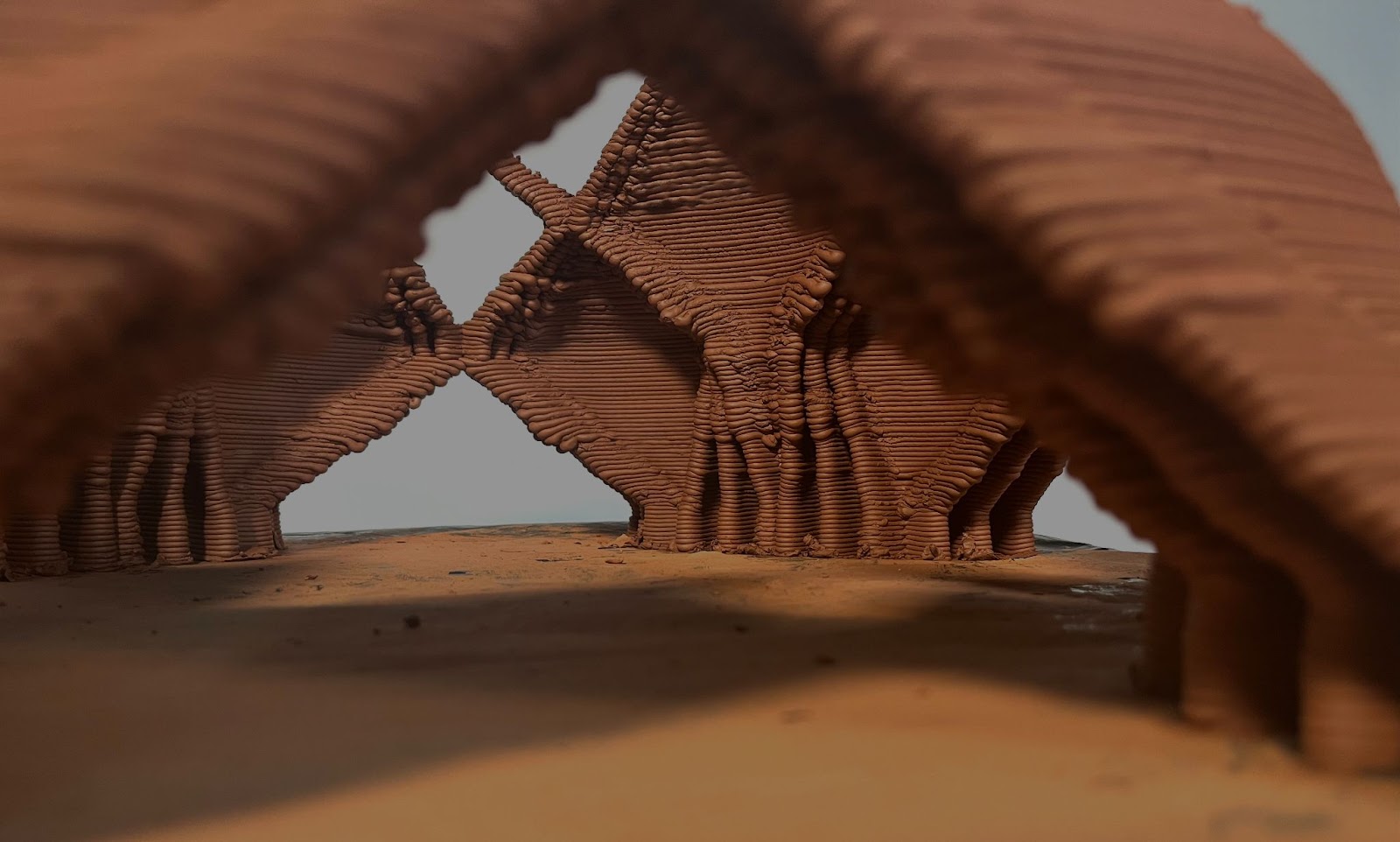
What are the possibilities of enclosing a free-form space?
The study reflects how geometry design will enhance the structural possibilities of increasing the maximum cantilevering degree of printing an enclosing surface. Applicability could be translated in printing projects above existent constructions and/or free-form developments.
The research was coagulated into two distinct parts, the exploratory phase, for extracting parameters for defining the geometry of a rib and enclosing the space phase, for defining the rib network.
Defining the Rib Geometry
To frame this study’s approach, as an initial constraint, points forming a quad were used as inputs to define the anchors of the surface.
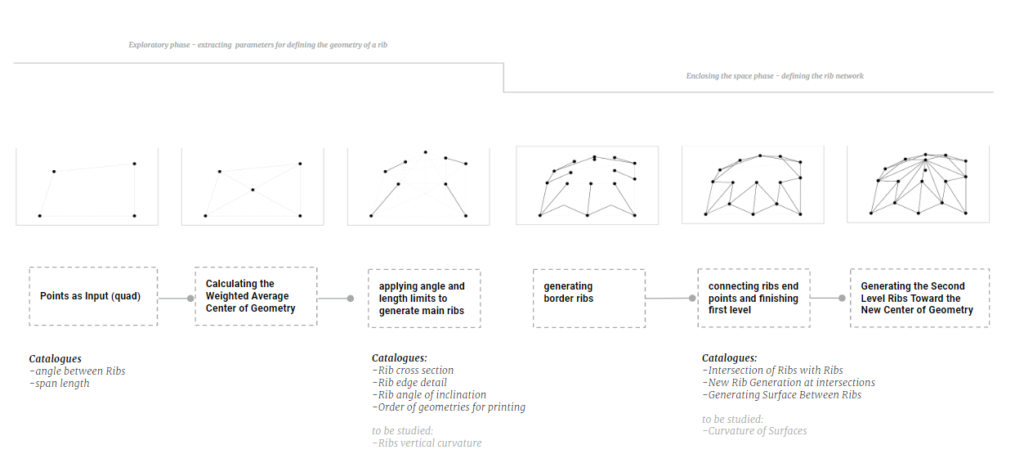
At the beginning of this research, the focus was put on finding the geometrical strategies that could form the anchor points or the rib starting points.
In order to define the behaviour of a wet state material, several catalogues were explored, such as Angle between ribs and angle of inclination, Rib sectioning, Mass distribution, Surface treatment, Infill, and Reinforcing the edge.
Exploring different parameters
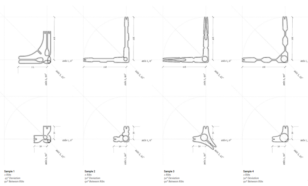
1/6 Angle between ribs and angle of inclination
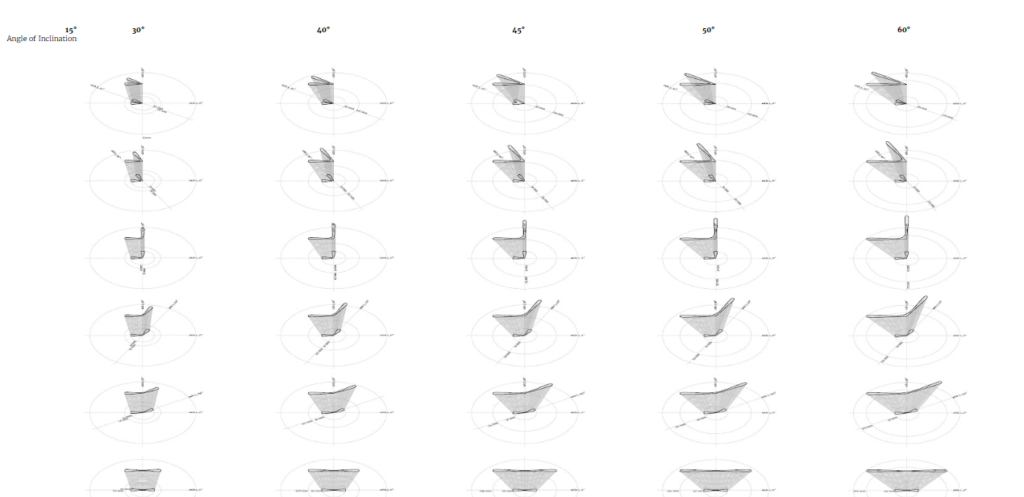
Notional directions of starting points for the rib network were explored through drawings, after setting a common base and the level of the cantilever for the print experiments to observe the moment of failure and identify the behaviour on an isolated geometrical fragment.
After printing in a linear path and studying the effect of angle deviation on various angle distances between the ribs, limiting the ribs’ angles parameter to 90 degrees for the moment was conceded, due to stability, allowing exploring further parameters.
2/6 Rib sectioning
The initial geometries involved a study about the relationship between two or multiple ribs’ effect on the base or anchor point. In the first iterations, the rectangular section of the rib added extra weight at the top causing buckling of the material, therefore the weight was reduced by shape in the following iterations. Slendering the top was applied as the first pragmatic geometrical enhancement.
3/6 Mass distribution
Furthermore, the affect of mass was studied for increasing the overall stability and as a first geometrical strategy, adding extra ribs to add weight and bring the centre of mass close to the geometry: ribs in between the main ribs, ribs at the back of the geometry, increased the stability of the geometry.
After defining the vertical contour of the geometry with the most vertical stability, we analyzed the impact of adjusting the toolpath and increasing structural integrity and decreasing deformation of the edge while in a wet state or dried.
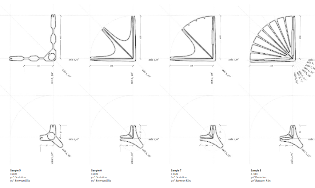
4/6 Surface treatment
More design explorations to enhance the geometry and avoid buckling consisted of iterations with increased local inertia in the vertical surface of the rib or various explorations on the surface that spans in between the ribs. These catalogues consisted of various studies on the curvature and texture of the surfaces, identifying the moments of failure for the isolated geometries.
5/6 Infill
Same geometry typology, different morphologies
Considering the previous experimental findings, the toolpath was designed for increasing the stability and global inertia by adding an infill that led to a mass increase in the anchor point, the printed iterations concluded that the geometry can be adjusted and the third leg could disappear by increasing infill, and the impact of the momentum could be reduced significantly.
6/6 Edge reinforcing
Also, designing a toolpath for creating ribs on the edges, by increasing the local and global inertia in the surface, adding an infill to increase global inertia, and creating a backwards movement in the geometry lowering the impact of momentum.
Surface enclosing
At this moment in the research, the focus shifted to the surface that spans over a perimeter and different strategies were applied in accordance with the previous geometrical explorations. Pulling back the geometry and implicitly the material increases the local and global inertia, hence enhancing the printability of the object.
Material optimisation
Momentum can be reduced by increasing mass in the anchor point and thinning the top of the rib to obtain a slender geometry.
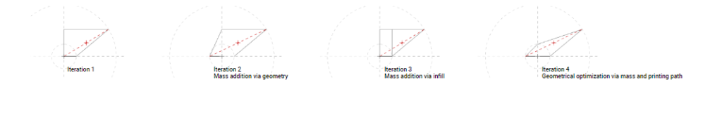
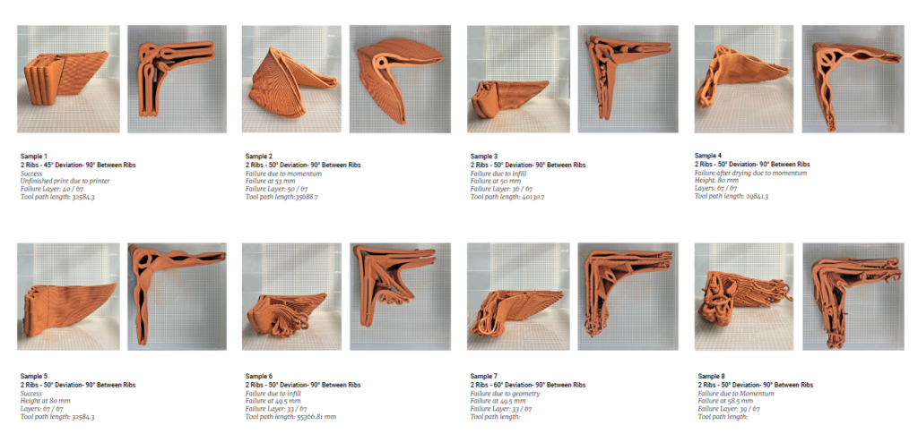
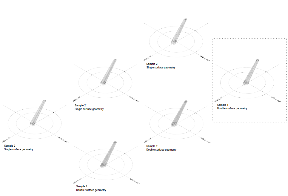
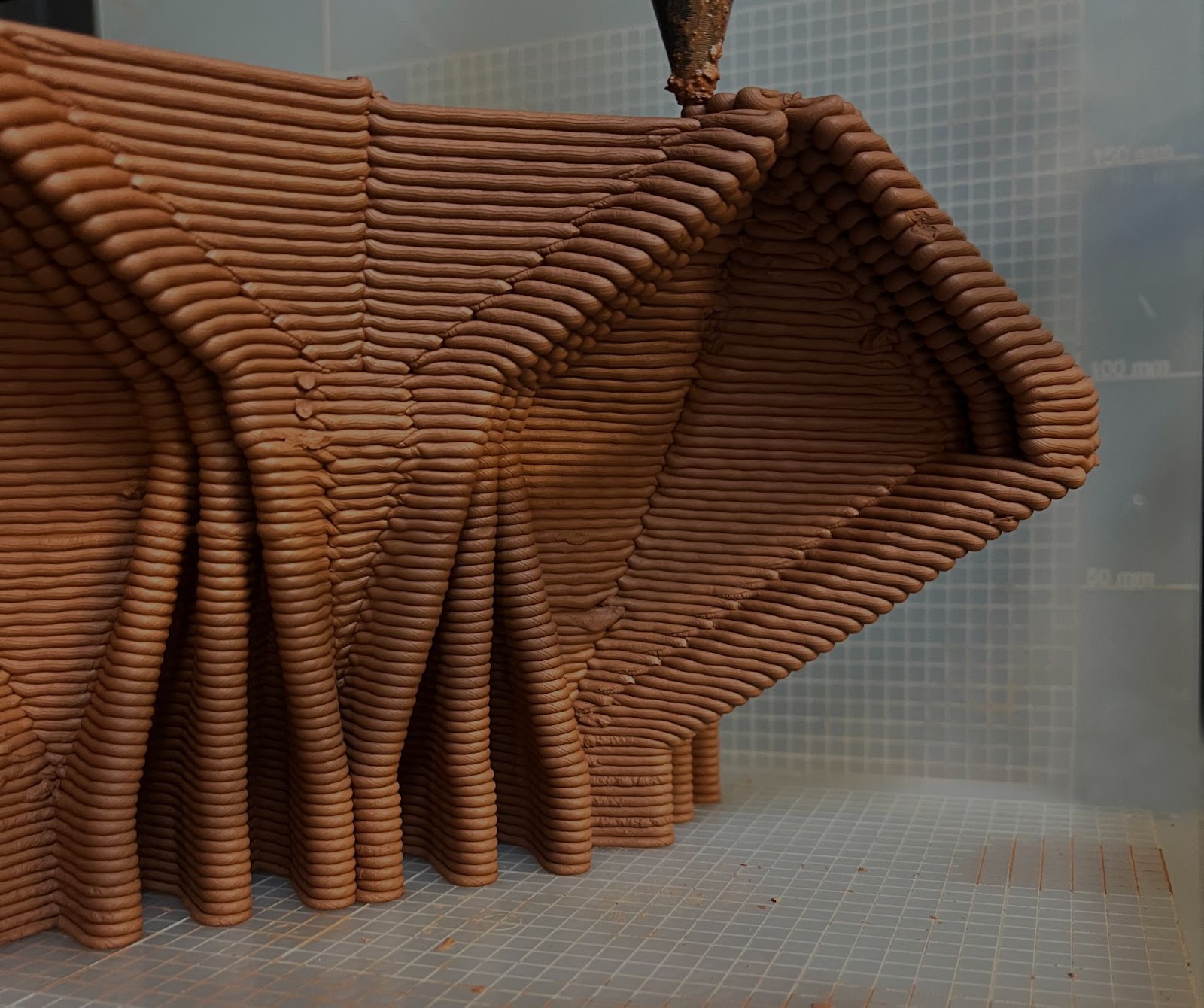
Furthermore, the exploratory phase was narrowed down to studying the geometry and behaviour of a single isolated rib geometry using the previous conclusions that led to geometrical optimization via mass and printing path: mass addition at the base, slender profile, and a toolpath that stiffens and folds the material through a radial period. Various geometries were compared during the design iteration process and printing process, with a single surface or double surface geometry, using the same parameters and cantilever inclination degrees.
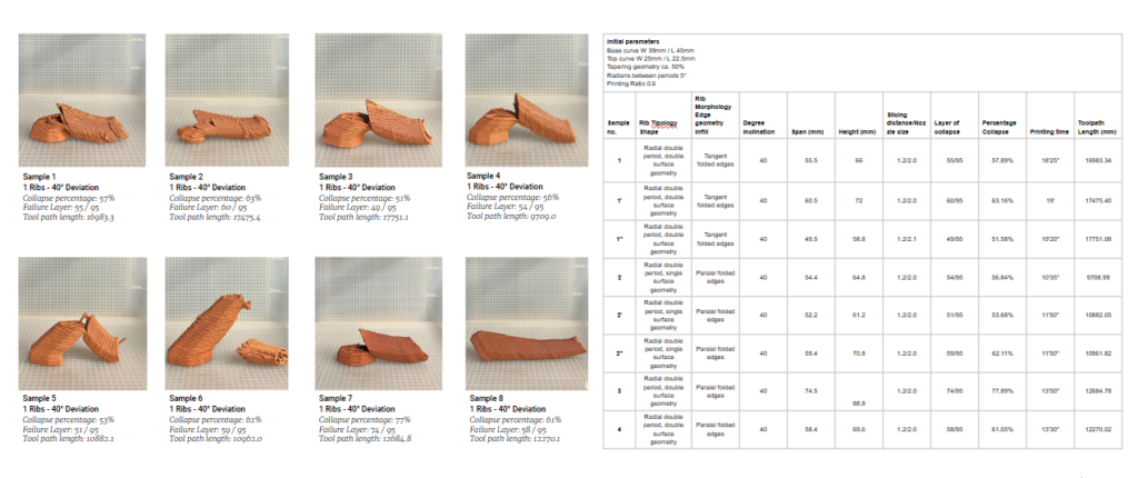
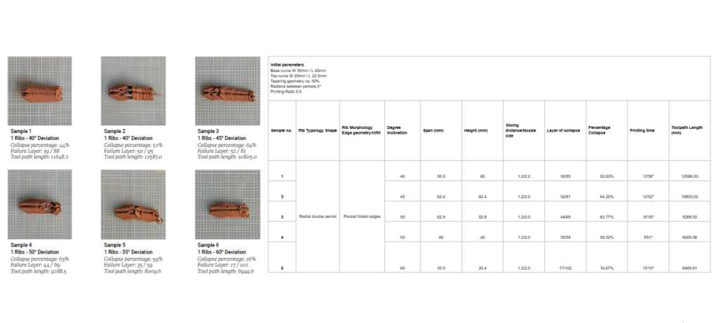
By this catalogue, the moment of failure recorded led to the geometry that behaved the best and reached the furthest, consequently, the following printing catalogue using this geometry and various cantilever inclination degrees was developed. Through the previously mentioned method, a safe span and length were identified and defined the initial parameters for creating the ribs generations that assemble the network enclosing the space. Using this data, the ribs can stop and intersect at a safe length and create newer generations on top of them, approaching the centre of the input quad.
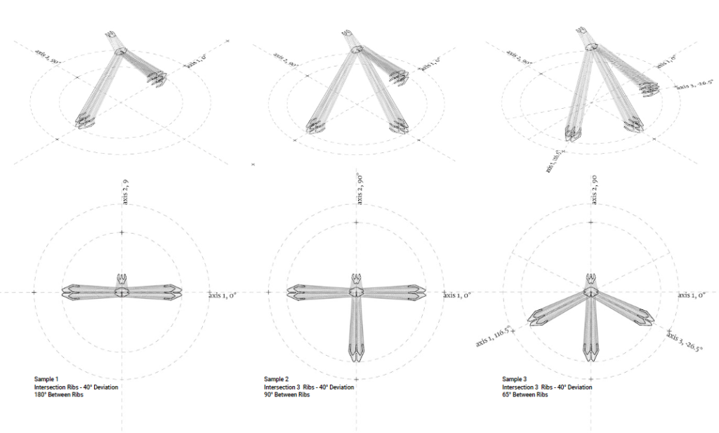
Intersecting Ribs to Form The Space
Creating the second generation of ribs was studied through design iterations and prints, exploring various kinds of intersections, and considering multiple ribs in the first generation that meet from various angles. In order to maintain the modularity of the system, and strengthen by the prints results, using the same rib geometry was considered. For the second generation of ribs, the transition of the infill was studied through various scaling on x and y to create a stiff connection between the two ribs generations.
Defining the Rib Network
As the research approached a desirable amount of geometrical information, the study pursued using the rib nodes in an ensemble. Iterations were made considering covering the area used as initial input. While printing failures of the surfaces were recorded in almost the same position regardless of the treatment applied to it – increasing curvature, increasing local inertia, creating inner ribs, and texturing. At this moment, confirming the rib intersections required printing the rib skeleton alone to identify the buckling and, therefore, the failing moment was due to a lack of rigidity in one of the rib generations category.
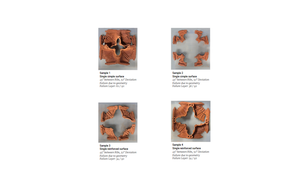
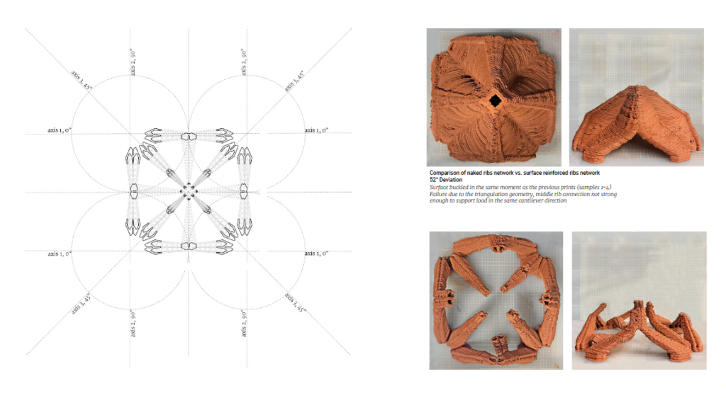
Applying the load in the same direction as the cantilever orientation was overloading the support one rib could hold. Concluding in re-designing the intersection nodes, based on the experimental information on the last prints, noticing that a new generation of ribs created over an intersection of two from a previous generation was behaving flawlessly.
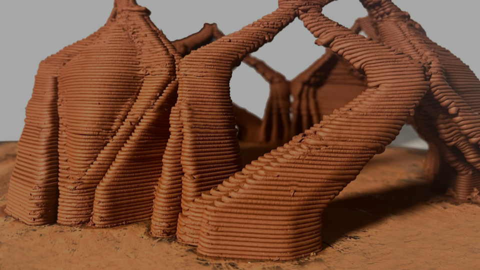
Final geometry, Enclosing a quad
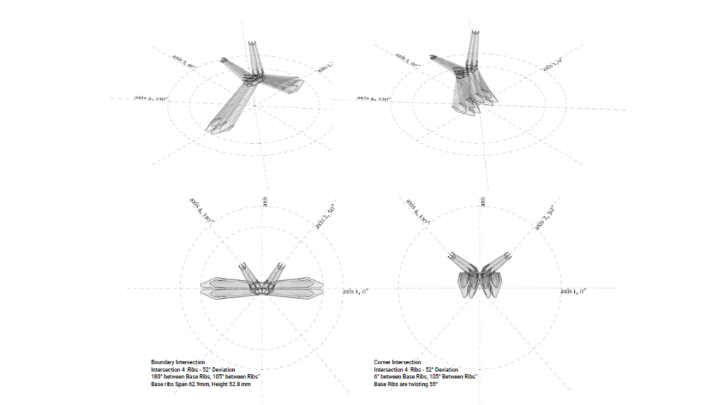
Hence, the rib network takes into consideration an updated rib meeting point and newer generations of ribs are created at an intersection of other previous two, regardless of their position, if boundary ribs intersection or corner ribs intersection.
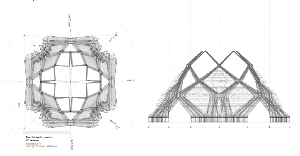
This system was proved on a 1:10 scale planar print using an Ender 5 printer and on a scale 1:3 scale using an ABB IRB 140 robot, which allowed a successful print till the third generation of ribs intersection.