Lessons from Workshop 1.1 – Robotic milling and design for subtractive manufacturing
This workshop focused on advanced subtractive manufacturing techniques, exploring the integration of 2-axis CNC milling and 6-axis robotic milling within a hybrid digital fabrication workflow. The process emphasized computational design-to-production strategies, including toolpath generation, material optimization, and robotic calibration. Through sequential stages of CNC cutting and robotic milling, the workshop demonstrated how digital precision, tool accessibility, and material behavior can be coordinated to achieve complex geometries and high-quality surface refinement in contemporary fabrication processes. It also taught us a great deal about the limitations of our tools – no matter how advanced they are. And how to navigate around those limitations to achieve an efficient design and fabrication workflow that meets our design requirements.
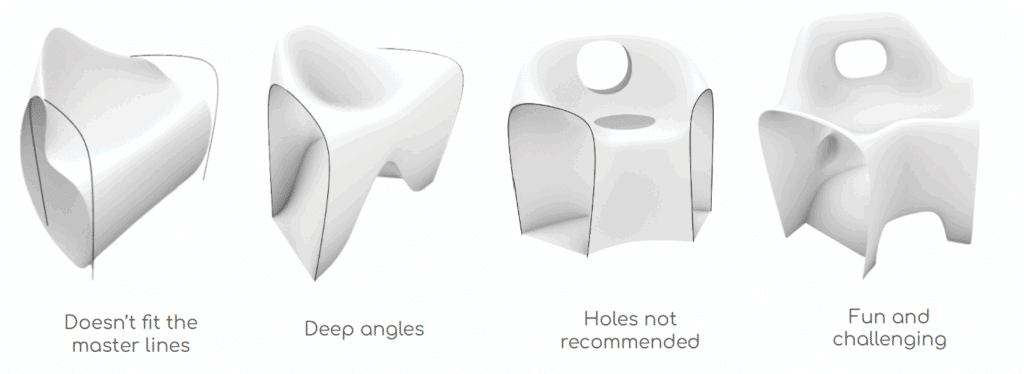
Phase 1: Designing the Chair
As a design constraint, we were given a set of master lines that enabled all the chairs fabricated by the class to be connected in a circular pattern. Other than that, we were encouraged to go as crazy as we can in terms of our chair geometries. We started by developing several design iterations and selected the one that excited us the most. See Figure 1. The idea of putting holes on a chair stemmed out of a toilet seat concept for a dry composting toilet. Realizing that such extreme angles at its small size cannot be reached by the robot’s huge spindle, we reluctantly settled with just putting one hole on the backrest and adding some bumps behind the chair just for fun. We did not design our chair to be comfortable.
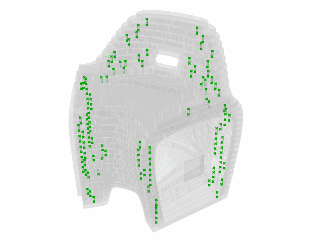
Before actually cutting the pieces of board that will make up our chair, we ran a quick draft angle analysis (see Phase 3) to check for manufacturability using the 6-axis robot. This step allowed us to make last changes in our geometry before actually cutting the pieces. Otherwise, we will be wasting time and resources for a geometry that cannot even be manufactured by our 6-axis robot. We later on learned that this draft analysis check was not enough. We should have run a full simulation of how the robot will go through each section of our chair. Since we were still learning the workflow and had to manage our time with all the other groups using the tools, we neither had the time nor the skillset to do those simulations at the time.
Phase 2: CNC Milling
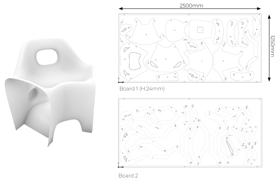
Once we’re content with our geometry, we created a model of the stacked version of our chair for CNC milling. Using an algorithm that was provided to us, we nested each piece on our boards such that it optimized the space within the two 2500mm x 1250mm x 24mm plywood boards that we were provided for this project. Once nested, we drew the position of the screws on the sides of our boards to keep them safely in place through the entire cutting process and ensure that the screws are never in the way of our tool’s path.
We configured the required parameters in the CNC software, including the toolpaths and material settings, to accurately translate the digital model into a physical prototype. We prepared the CNC files with the settings for each operation, making sure that everything is cut and drilled as we intend them to be.
The first board used a total area of 1.73㎡ and took 94.18 minutes to cut, while second board used an area of 1.11㎡ and took 119.77 minutes to cut. Overall, CNC cutting took about 3.5 hours to finish.
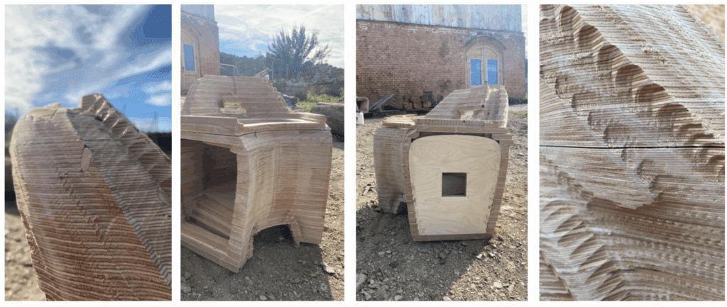
Phase 3: Assembly
Each layer of plywood requires two sets of dowels for alignment, connecting the upper and lower pieces. Glue is applied to keep them together. During assembly, several issues arose:
Tolerances for cutting: Each wood layer has a 24-mm pre-cut hole for the dowel. However, the CNC machine, being a machine, can have tolerances of up to a few decimal places. Although we measured the thickness of the board, it’s also possible that in some places, it could be slightly more than 24mm. So we had a few dowel holes that were not drilled through and through.
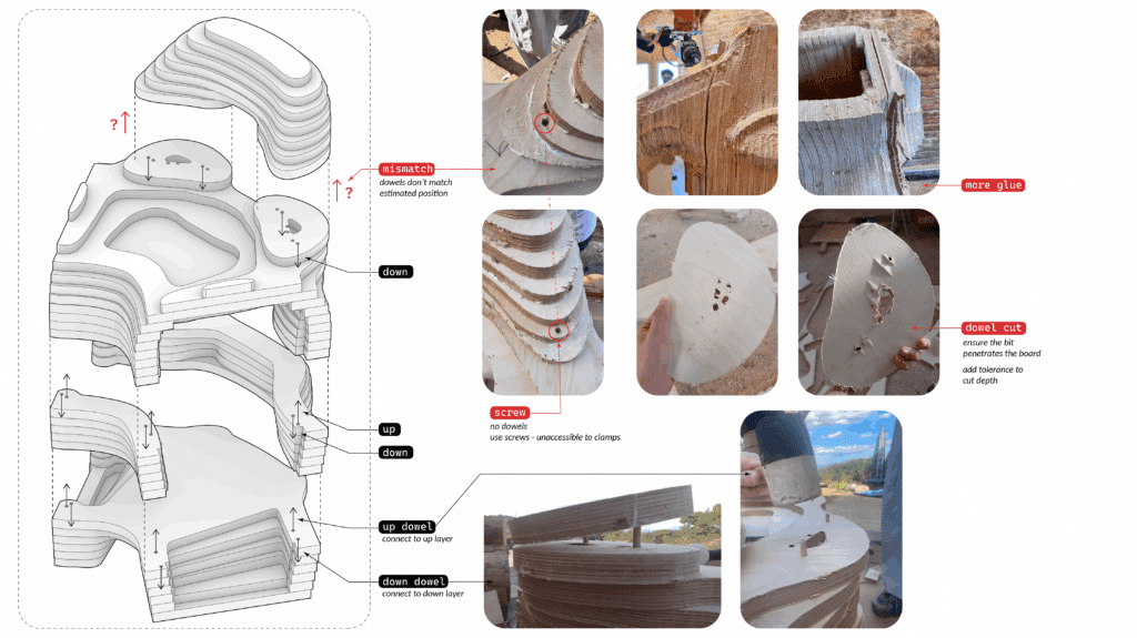
We should have set the drilling depth to be slightly deeper than the actual 24mm height of our material. Nonetheless, the issue was easily resolved by simply using a drill to punch through the remaining material in the dowel holes. We also sanded our pieces a bit just to remove the rough materials at the edges that would have been in the way of nicely stacking and glueing the pieces together.
Mismatch of dowels: Each piece was designed to have four dowel holes for stacking alignment. Two holes for the layer on top of it, and two for the layer below it. However, on the 20th layer, the algorithm generated 6 dowel holes for each piece, and two extra tiny pieces that didn’t have holes in them. Those tiny pieces would have been milled away anyway considering its size. With that in mind, we learned that we also could have avoided the issue if we understood – through simulations – how much material our 6-axis robot will be taking away before we even started cutting our pieces. The nesting algorithm could have also been optimized to avoid such dowel hole arrangements in the future.
To ensure a tight stack as the glue dries, we used clamps to keep our stacked geometry together. In the process, we noticed that our geometry is not clamp-friendly. Something that we could have accounted for in the early design stage if we knew ahead how much we needed to clamp them. In the end, we resorted to drilling screws in the places where the clamps cannot be attached. We just reminded ourselves to remove them before milling. A screw or any metal part colliding with our robot’s tool could: (1) break the tool, (2) break our robot, or (3) send debris flying all over the place, putting everyone at risk.
Phase 4: 6-Axis Robotic Milling
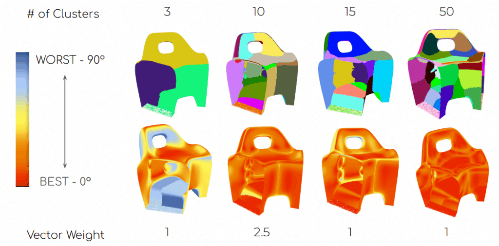
Draft Angle Analysis: We were provided an algorithm that divides our geometry into multiple patches. Each patch is made such that it allows the robot’s tool to have one angle of approach for the entire patch. We had a gradient scale of red (best angle: 0°) to blue (worst angle: 90°) in the algorithm. We designed our chair to avoid the 90° angles.
The algorithm allowed us to simulate varying numbers of patches, taking into account that one patch corresponds to one milling file that has to be performed by the robot. We varied our patches from 3, 10, 15, 30 and 50. In addition, the algorithm allowed us to vary the vector weights on the clustering of the patches. Thus, changing the size and arrangement of each set of patches. We eventually settled with 10 patches at a vector weight of 2.5.
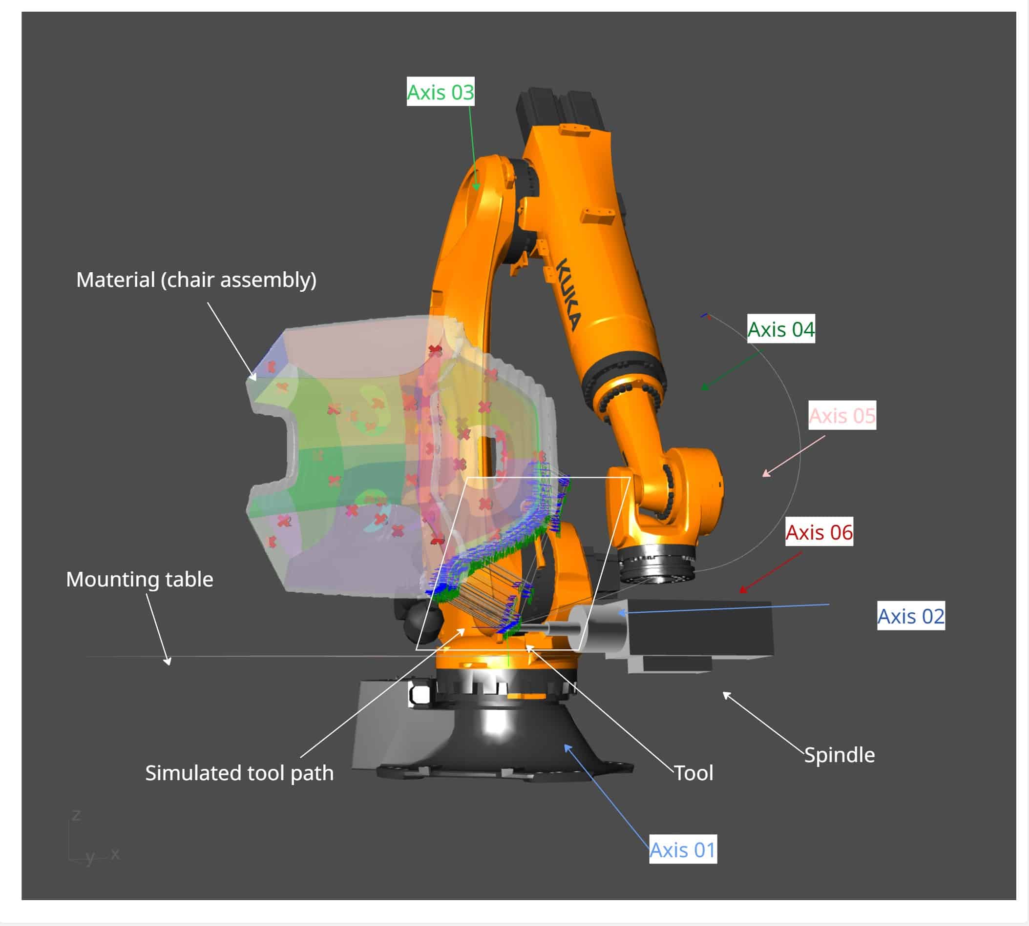
Robotic milling strategy: For the simulation of the robot’s tool path, the algorithm further divided the 10 patches into 38. For each patch, we had to manually examine the robot and the tool’s path making sure that: (1) The robot does not collide with itself, (2) the robot does not collide with the mounting table, our geometry or other objects that might be in the room, (3) the robot’s tool and/or spindle does not collide with our material and (4) the robot does not make any sudden movements in any of its 6 axes. Each simulation generates a file that contains instructions for the robot. Each file has to be initiated manually by the user/robot operator (us).
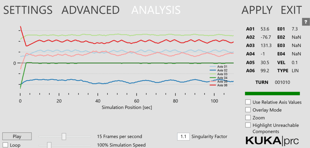
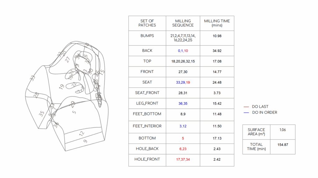
Running the simulations, we understood that some patches are best milled first so that we could create more space for the tool to maneuver in the tight spaces. With that in mind, we created a sequence of how we will load each patch file to the robot. The robot controller displays all loaded files alphabetically, so we created the filenames such that patches that go together have similar filename prefixes. This reduces error and saves time on the part of the user/robot operator. For our chair geometry, we had the following patch filenames: BUMPS, BACK, TOP, FRONT, SEAT, SEAT_FRONT, LEG_FRONT, FEET_BOTTOM, FEET_INTERIOR, BOTTOM, HOLE_BACK, HOLE_FRONT. We prioritized milling based on the position and difficulty. The total milling time was estimated to be 154.87 min (~2.5 hours), but it does not take into account the time it takes for the robot to maneuver back to its home position after each file is finished and the time it takes to load each file. For estimation purposes, the total milling time can be about twice as long as the simulated time, considering our skillset and familiarity with the robot controller.
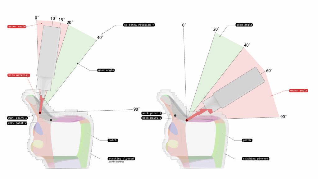
Issues encountered: Despite all of our planning and simulations, we still encountered a collision between the spindle and our material. The figure below shows our tight maneuvering space for patch SEAT_19. The spindle hit the back rest of our chair and it snapped loose. At this point, we had to stop milling.
Possible solutions:
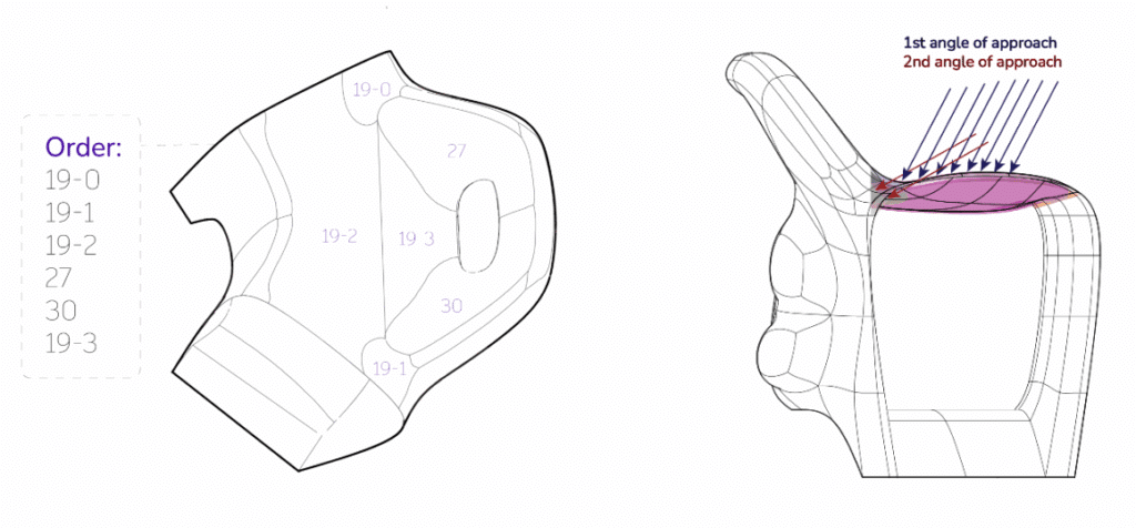
- We could divide patch SEAT_19 further into four parts (See Figure 8 [RIGHT]). Add then mill the parts that are away from the hole first, including the patches on the back rest (FRONT_27 and _30), before going in to mill the parts that are in the hole.
- It was not available in the algorithm provided to us at the time, but it’s also possible to change the angles of approach within one patch so that we can avoid some material in the tight spaces. See Figure 8 [LEFT].
- We could have used more glue in stacking our pieces together and made sure we clamped them before they dry. However, one consideration that we had during assembly was that too much glue oozing over the sides may take more time to dry, when we have a tight timetable. Moreover, glue is the non-biodegradable part of this chair and we were conscious not to use more than what was necessary.
In conclusion, while we were unable to finish milling our chair, it provided a lot of valuable insights and experience that could help us create better design and fabrication workflows in the future.