3D Printing | Kinetic Facade
| CONCEPT |
The project draws its primary inspiration from the dynamic, sun-responsive mashrabiya system of the Al Bahr Towers in Abu Dhabi. What captivated me was the sharp visual contrast between conventional, static façade geometries often rectilinear or triangulated and the refined kinetic intelligence embedded in these triangular adaptive screens.
This tension became the conceptual foundation for developing a 3D-printed material system that, although produced within a square printing frame, expresses itself through a field of articulated triangular modules. The ambition was to capture the elegance and performative sophistication of kinetic facades: enabling light to filter through shifting triangular apertures while generating multiple shading conditions.
In doing so, the material echoes the Towers’ capacity to modulate transparency, shadow, and solar exposure translating a high-performance architectural principle into a digitally fabricated, small-scale component.
| REFERENCES |
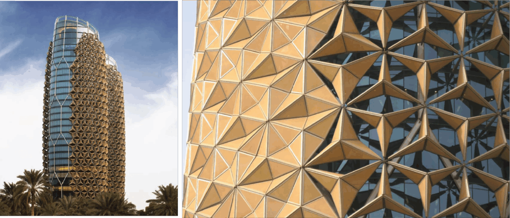
Our main source of inspiration for this design was the Al Bahr Towers by AEDAS.
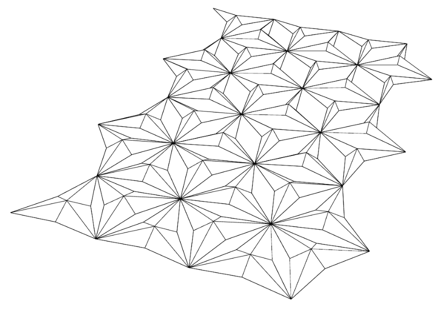
| PROJECT DIAGRAMS / TECHNICAL DRAWING |
Design Iteration 1:
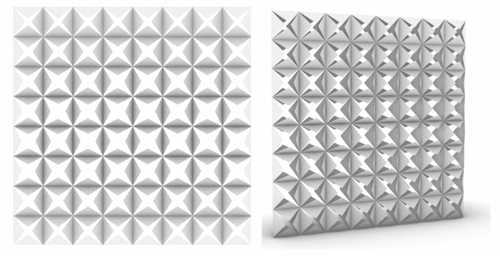
For our first iteration of the design, we used a parametric modeling script to create a form similar to that of the facade of Al Bahr tower as our starting point. We added half spheres as connection points at the vertices and used a printing strategy with two layers of rafting to test the structure.
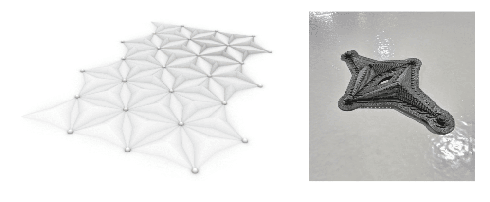
Design Iteration 2:
Our first test demonstrated a lack of structural stability at the connection points that resulted in being unable to remove the rafting without destroying the form. We iterated increasing the scale of the spherical joints in relation to the overall form.
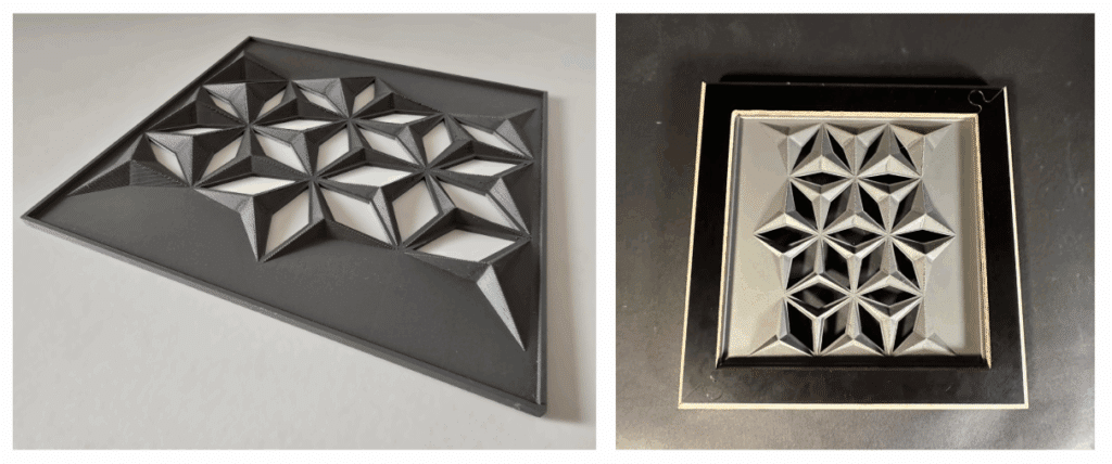
Final Iteration:
Our second test was successful in improving structural stability. We decided to further iterate by introducing variation in movement along the access. We also wanted to be able to remove the spherical joints, so we created a version of the design that would incorporate a permanent “rafting” strategy that would maintain the porosity of the design while providing structural stability.
| FABRICATION: PROTOTYPING |
In our final iteration, we refined the external layer of our model using the ironing function of the 3D printer to accomplish a smooth finished surface.
| FINAL PRODUCT |
| FUTURE ITERATION |
For the next iterations, we aim to explore the possibility of making the triangular domes hollow and more slender, allowing them to better embody our initial reference to the Al Bahr Towers. Although the current geometry could be interpreted as a milling operation, our intention is to move away from that reading. To do so, we plan to design full openings with defined anchor points, maintaining the project’s original playful organization of geometries while also pushing the limits of the 3D-printing process capabilities.
——————————————————————————————————————————————————————————————————————————-
CNC Milling | Parametric Triangular
| CONCEPT |
The main inspiration comes from the marked visual dichotomy between conventional, predominantly square architecture and the geometric sophistication of triangular facades. This contrast was key to conceiving a material that, while inscribed within a square frame, is articulated through a dynamic pattern of triangles. The objective was to evoke the elegance and modernity of these facades, reflecting their capacity for light interaction by allowing light to creatively filter through the triangular openings within the wooden composition.
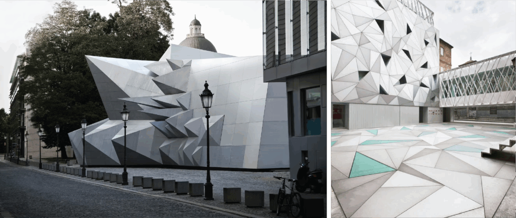
| REFERENCES |
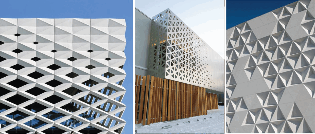
Our main sources of inspiration for this design were the Ichii Renovation Hakodate by PODA, and the Gallery of Eastland Town Center by ACME Architects.
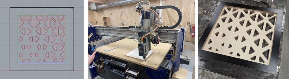
| PROJECT DIAGRAMS / TECHNICAL DRAWING |
The design began with inspiration from triangular modular facades. Using Rhino and Grasshopper, complex geometric patterns were explored, varying sizes and configurations.
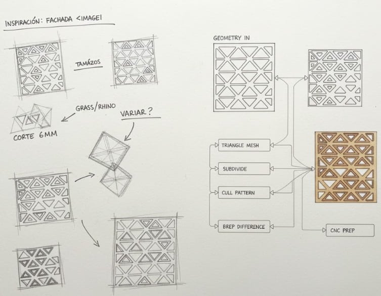
| FABRICATION: PROTOTYPING VERSION 1 |
A pre-prototyping phase, with simpler cuts, allowed for the final geometry to be refined. Finally, the design was prepared for CNC cutting in Plywood with a 6mm tool, seeking to optimize material consistency and cut precision to create the new composite material.
Rhinoceros 3D/Grasshopper Horizontal Pocketing Final Product – Post Profiling
| Material: Plywood | Bit: Flat Mill | Cut Direction: Downcut | Machine: CNC Shopbot | Flute: 2 Stepdown Control (dZ): 70% | Post Processor: Raptor X | Diameter: 6 mm | Stepover Distance: 50% | Workpiece volume: 400x400x15mm | Spindle Speed: 12000 | Total mill time: 28 minutes |
| FABRICATION: PROTOTYPING VERSION 2 |
For our final prototyping stage, we aimed to explore the potential of using a ball mill to achieve cleaner finishes and smoother, rounded edges. Our initial concept involved infilling the milled pockets with two different materials; however, due to concerns about material waste, we shifted our approach. Instead, we investigated how exposing the natural stratification of the plywood could generate contrasting textures, creating the visual effect of multiple materials without introducing additional waste.
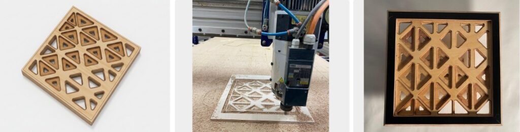
Rhinoceros 3D/Grasshopper Horizontal Pocketing Final Product – Post Profiling
| Material: Plywood | Bit: Flat Mill/Ball Mill | Cut Direction: Downcut | Machine: CNC Shopbot | Flute: 2 Stepdown Control (dZ): 70% | Post Processor: Raptor X | Diameter: 8 mm | Stepover Distance: 50% | Workpiece volume: 400x400x15mm | Spindle Speed: 12000 | Total mill time: 43 minutes |
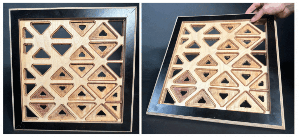
| FINAL PRODUCT |
Laser Cutting | Folding Origami
| CONCEPT |
The project is inspired by the visual tension between conventional, square-based architectural geometries and the refined complexity of triangular façade systems. This contrast informed the development of a foldable material logic that, although constrained to a square laser-cut sheet, unfolds into a dynamic field of triangular units.
Fabricated from laser-cut polypropylene, the system translates the elegance and structural clarity of contemporary triangular facades into a flexible origami assembly. As the polypropylene surface is folded, triangular apertures modulate light and shadow, allowing illumination to pass through the pattern in a controlled, expressive way.
Our main sources of inspiration for this design were the Pavilion 21 MINI Opera Space by Coop Himmel, and the ABC Centre by Aranguren & Gallegos.
When considering folding techniques for laser-cut fabrication, the immediate reference was the Japanese art of origami. This traditional practice relies on a precise, sequential system of folding a single planar element to generate complex geometries. Drawing from this procedural logic, the concept informed the early stages of our prototyping process, guiding the initial ideation and organization of folds for the prototype.
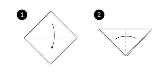
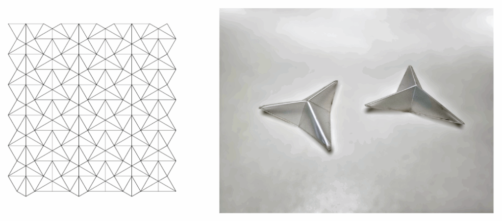
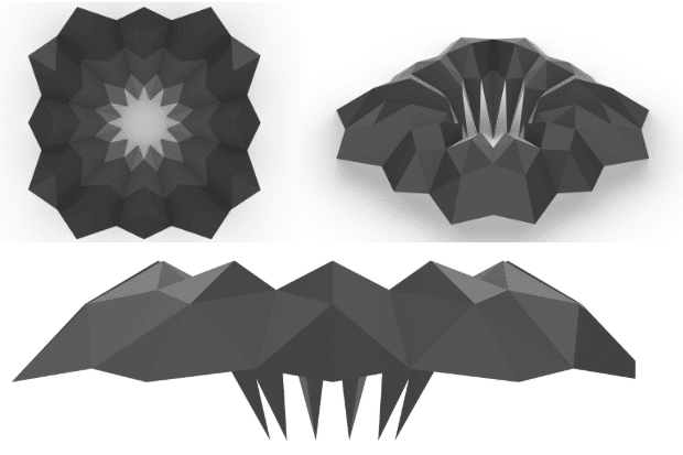
| STRATEGY 1: 3D MODELING FLAT TO FOLD |
| PROJECT DIAGRAMS / TECHNICAL DRAWING |
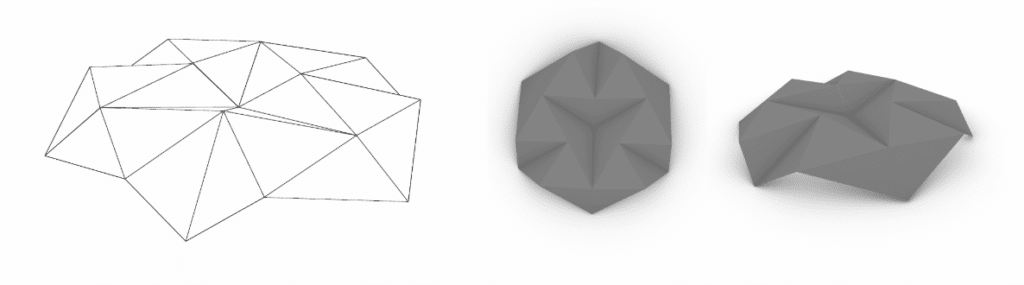
For our first iteration, we began in the 3D modelling space, experimenting with visual form before translating the design into linework.
| PROTOTYPE 1 |
| FUTURE CONSIDERATIONS |
Lessons Learned: Folding techniques are challenging. There’s a lot of consideration regarding not just the durability of the material but the folding design itself. Its a pretty short line between success and failure. You have to understand in depth the foldings of your piece to identify where you need to cut, crease or just mark, for foldings go both ways, inwards and outwards. The final challenge for this piece was morphing the piece together. The ideal scenario involves creating a unifying system that takes into consideration the morphology and unified strategy. The process varies in detail management but demands full attention and consideration at all times.
Next Steps: For the following iterations, the strategy will shift toward exploring a different growth direction. This folding directed itself to a vertical vector that opens the folding like an umbrella. That vertex itself proved to be a challenge, but after further consideration we believe printing multiple pieces with different vertex in each can be a beneficial aspect to the morphological richness of the piece.
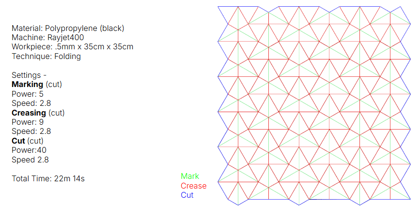
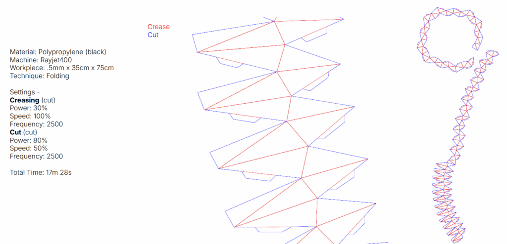
| STRATEGY 2: ITERATING 2D TO 3D |
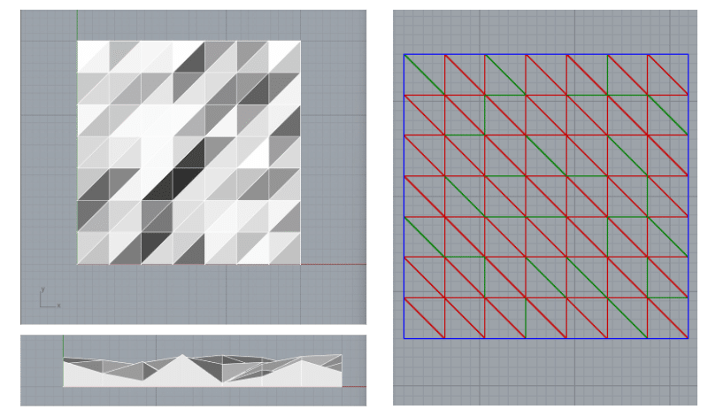
| PROJECT DIAGRAMS / TECHNICAL DRAWING |
We applied what we learned in the first iteration to experiment with linework and folding techniques, moving between 2D drawings and 3D physical tests. We also used this process to refine the power settings of the laser cutter to create optimal cut depth for creasing.
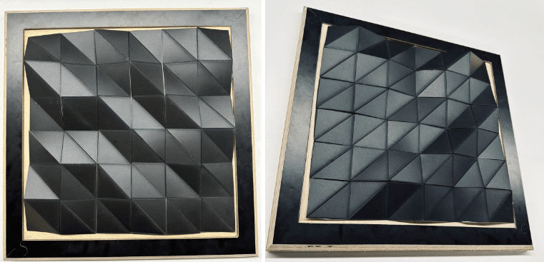
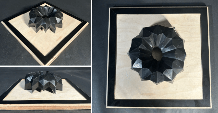
| PROTOTYPE 2 |
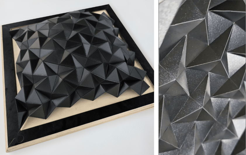
| FUTURE CONSIDERATIONS |
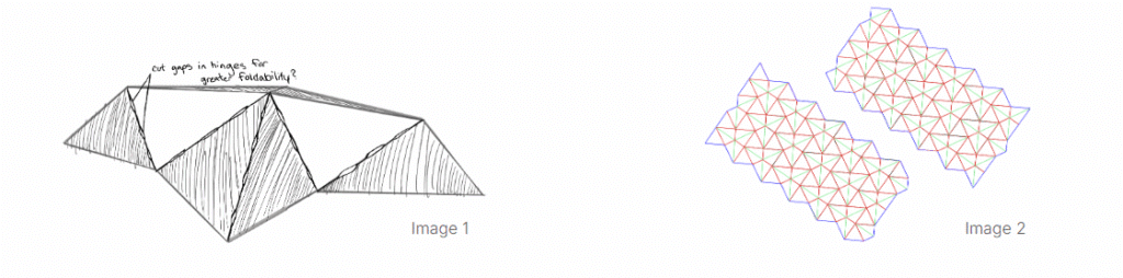
Component Scale: In the manual folding process of our design, we discovered that, while folding the components close to the edges was relatively easy, manipulating the interior components was extremely difficult. In a next iteration, we would like to experiment with increasing the component scale within the design to improve access and maneuverability. Other variables we would like to experiment with include altering the hinge type (e.g., cutting sections of the hinges to increase foldability as in image 1) and cutting the design into multiple sections to reduce the distance between components and edges (image 2).
Structural integrity vs. ease of manual manipulation: Within the strategies proposed in the previous point, we will need to consider how changes affect the strength of the structures structural integrity. Our current prototype, while difficult to work with, provides a quite rigid final form. We will need to iterate and refine to achieve a balance between practical ability to manipulate the form and maintaining structural integrity.
| STRATEGY 3: EXPLODING 3D FOLD |
| PROJECT DIAGRAMS / TECHNICAL DRAWING |
We developed an alternative iteration in which we also explored in the 3D modelling space with visual forms resembling the triangular shapes with a twist. This time we assembled the foldable model before translating the design into linework.
| PROTOTYPE 3 |
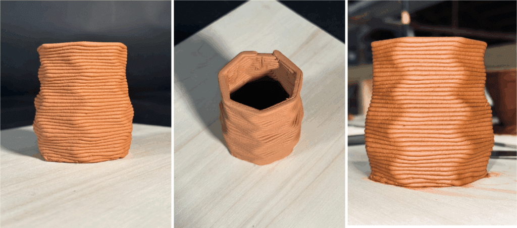
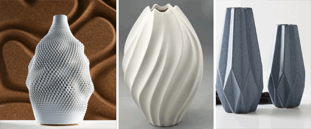
Robotics | Ceramic Cup
| CONCEPT |
While designing a parametric ceramic cup, we explored a range of geometries to test the capabilities and limits of the 6-axis ABB 140 robotic arm. The digital fabrication of these prototypes became particularly compelling, as the inherent materiality of the clay produced a natural, organic character. Additionally, experimenting with different end-effectors opened up a wide spectrum of formal and textural outcomes, highlighting the versatility of robotic ceramic fabrication.
| PROJECT DIAGRAMS / TECHNICAL DRAWING |
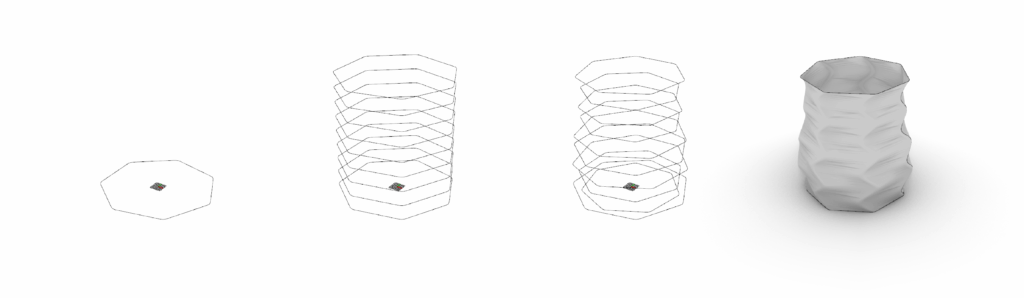
| FABRICATION: PROTOTYPING |
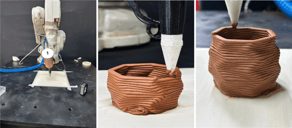
| FINAL PRODUCT |