Simulate. Forecast. Outpace failure.
Abstract
AssetPulse is an advanced asset management simulation tool and synthetic data generator designed to optimize resource allocation, improve decision-making, and facilitate research through realistic scenario modeling. Building on a graph-based approach, AssetPulse models asset lifecycles, calculates remaining useful life (RUL), and applies business rules for budget planning, risk management, and both reactive and preventive maintenance. The system aggregates risk, cost, and downtime metrics, supports automated scheduling, and visualizes results through an interactive interface. By enabling robust scenario analysis and comprehensive planning, AssetPulse helps users optimize maintenance strategies and resource allocation for complex building systems and infrastructure networks. This paper discusses the objectives, research questions, methodology, and future work related to the project.
Introduction
Problem
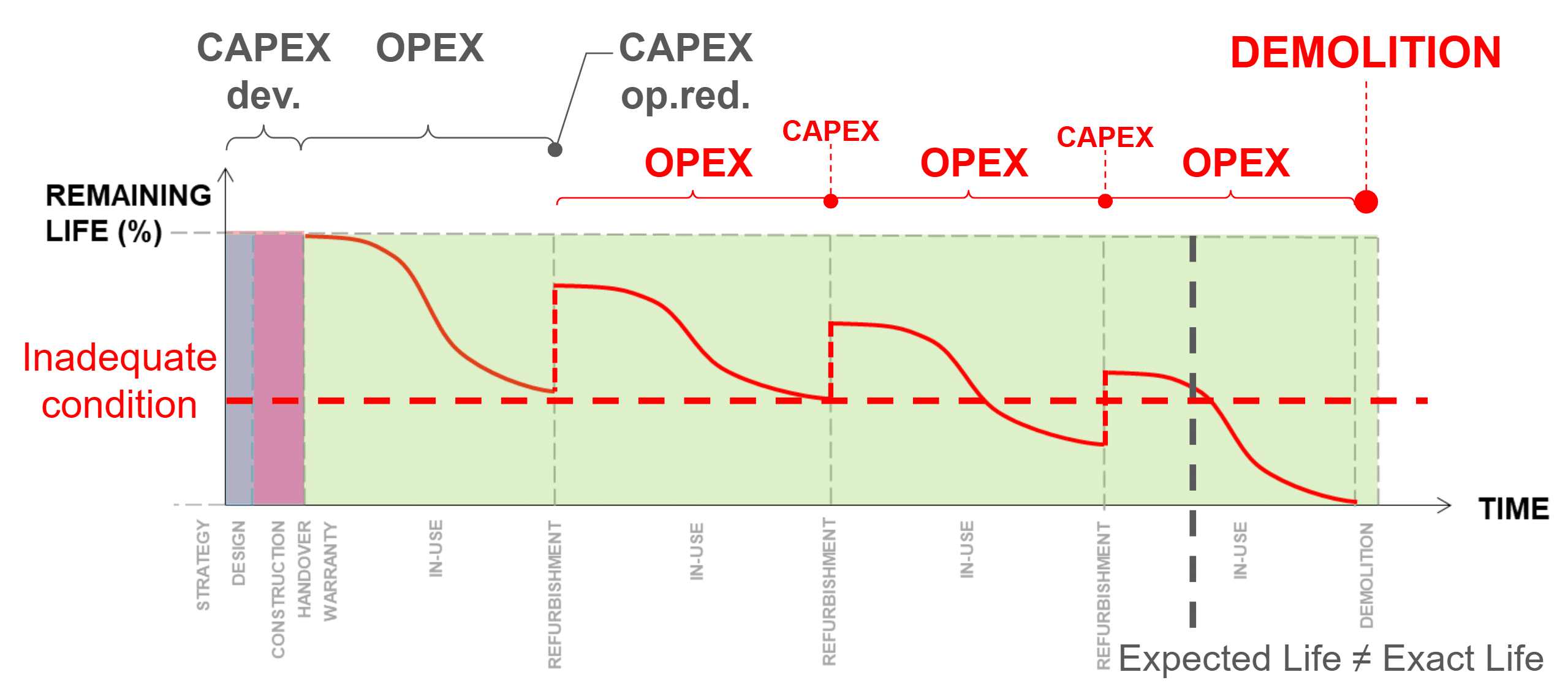
Effective management of physical assets is critical for operational efficiency and cost control across industries. However, many organizations face challenges in modeling asset lifecycles, predicting maintenance needs, and allocating resources optimally due to a lack of data-driven decision-assistance tools. The financial impact of operational readiness-related refurbishment works and frequency of maintenance activities is difficult to forecast or measure, while on an empirical basis, they are potent cost savers in the long run. Meanwhile, the ROI of infrastructure development-related CAPEX works is relatively straightforward to forecast and justify, hence they are overly favored during budget allocations.
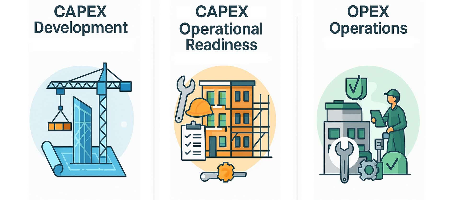
New construction with clear ROI – easier to forecast, measure, and de-risk.
Refurbishments with uncertain returns – difficult to budget, predict, or measure.
Routine maintenance – easier to justify, but often deferred under operational pressure.
Too often, asset management decisions are made based on historical practices or intuition rather than data-driven insights, leading to suboptimal outcomes. Additionally, the complexity of asset networks and the interdependencies between different components make it challenging to assess risk and prioritize maintenance activities effectively, without comprehensive modeling and simulation capabilities.
AssetPulse aims to address these challenges by providing a simulation environment that allows users to model asset behaviors, evaluate different budget strategies, and make informed decisions based on simulated outcomes.
Research Questions
- How can graph-based methods support the tracking of changes and lifecycle management of building systems?
- How can synthetic data generation be utilized to create realistic asset management scenarios for testing and validation?
- What are the comparative advantages of different budget allocation strategies in asset management?
- How can simulation tools be designed to facilitate user interaction and decision-making in asset management?
Objectives
- Develop a graph-based simulation tool that models asset management scenarios, including asset lifecycles, maintenance schedules, and budget allocations.
- Create a synthetic data generator to produce realistic datasets for testing and validating asset management strategies.
- Enable users to visualize and analyze the impact of different asset management decisions through interactive dashboards and reports.
- Compare the effectiveness of various budget allocation strategies in asset management through simulation experiments.
- Optimize budget allocation strategies based on different metrics such as maximizing asset longevity, maximizing equipment condition, and minimizing monthly costs.
Interface
We designed an intuitive user interface that allows users to easily set up simulation scenarios, define asset parameters, allocate budgets, and visualize results. The interface includes features such as file upload/download, interactive graphs, and customizable reports to enhance user experience and facilitate decision-making.
We see the interface as both a research tool and a practical application for asset managers, enabling them to explore various strategies and their outcomes in a user-friendly manner. While the interface is not a finished product, it provides a solid foundation for future development and refinement based on user feedback and evolving needs in asset management. And despite its current limitations, it effectively demonstrates the core functionalities and potential of the AssetPulse system.
The interface is built using the Panel library from Holoviz, which provides a flexible and robust framework for creating interactive web applications in Python. It can be easily extended and customized to meet specific user requirements and integrate additional features as needed. It also supports deployment as a standalone web application or integration into existing asset management platforms, as a future area of improvement.
See Appendix A for an example test dataset representing a simple building.
See Appendix B for an example test dataset representing a more complex building.
See Appendix C for screenshots of the current user interface.
Methodology
Overall Architecture and Workflow
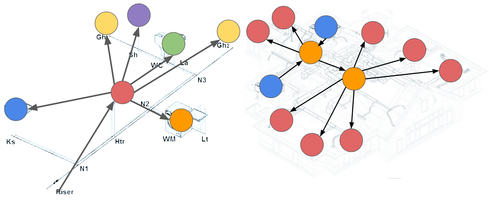
The following diagram illustrates the overall architecture and workflow of the AssetPulse simulation tool, including key components such as the user interface, graph controller, simulation engine, and data storage.
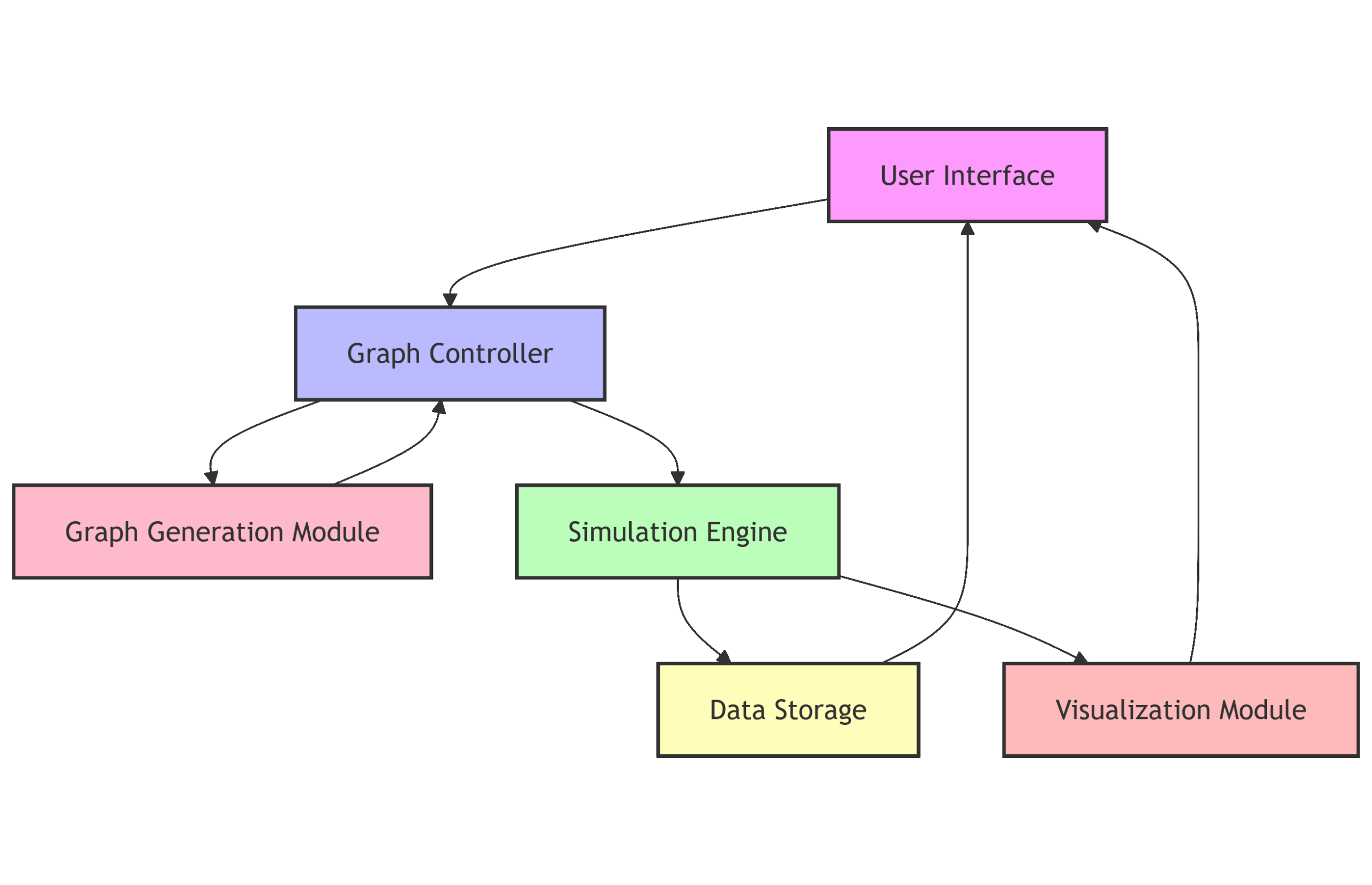
The workflow begins with the user interacting with the interface to define simulation parameters and upload necessary files. The graph controller manages the creation and manipulation of asset graphs, which are then processed by the simulation engine to model asset behaviors and outcomes. Results are stored in a database and visualized through interactive dashboards, allowing users to analyze and interpret the data effectively.
Simulation Tool Development
- Graph-Based Modeling
- Utilize graph structures to represent assets, their relationships, and lifecycle
- Simulation Engine
- Implement a simulation engine that allows users to define scenarios, allocate budgets, and simulate asset behaviors over time.
- User Interface
- Design an intuitive user interface for scenario setup, simulation execution, and result visualization.
- Synthetic Data Generator
- Develop a module to create realistic synthetic datasets that mimic asset characteristics, failure modes, and maintenance histories for testing and validation purposes.
- Validation and Evaluation
- Conduct experiments to validate the simulation accuracy and evaluate the impact of different budget allocation strategies using the synthetic data.
Synthetic Data Generation
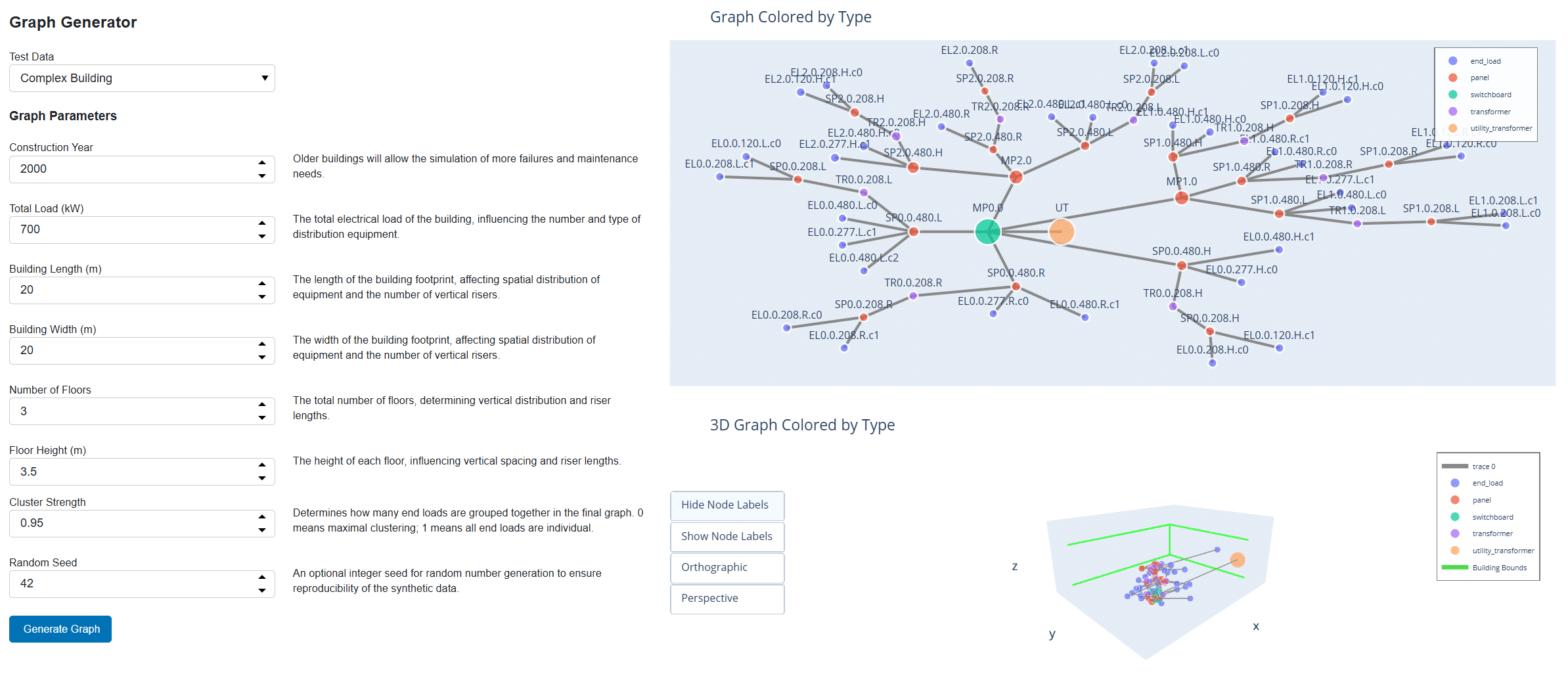
We were unable to acquire appropriate real-life dataframes and decided to build the application using synthetic data. To quickly generate realistic building data for testing and validation, we developed a synthetic data generator. This tool creates building electrical system graphs based on the following user-defined parameters:
User-Defined Parameters
- Construction Year: Older buildings will allow the simulation of more failures and maintenance needs.
- Total Load (kW): The total electrical load of the building, influencing the number and type of distribution equipment.
- Building Length (m): The length of the building footprint, affecting spatial distribution of equipment and the number of vertical risers.
- Building Width (m): The width of the building footprint, affecting spatial distribution of equipment and the number of vertical risers.
- Number of Floors: The total number of floors, determining vertical distribution and riser lengths.
- Floor Height (m): The height of each floor, influencing vertical spacing and riser lengths.
- Cluster Strength (0-1): This parameter determines how many end loads are grouped together in the final generated graph. It does not affect the distribution equipment generation. A value of 0 means that all end loads will be maximally clustered, while a value of 1 means that all end loads will be individually included.
- Random Seed: An optional integer seed for random number generation to ensure reproducibility of the synthetic data.
Building Electrical System Generation Logic
The synthetic data generator uses the provided parameters to create a building electrical system graph. The process involves:
- Define Building Characteristics
- Validate and record user-specified parameters such as total electrical load, building dimensions, number of floors, and floor height. Calculate derived attributes like total area.
- Determine Number of Vertical Risers
- Calculate the number of risers required for efficient electrical distribution, based on building area and a rule of thumb (e.g., one riser per 500 square meters per floor).
- Locate Risers
- Place risers within the building footprint, spaced along the longer dimension and centered along the shorter dimension, with some randomness to avoid perfect regularity.
- Determine Building Voltage Level
- Select the appropriate voltage system (e.g., 120/208V or 277/480V) based on the total electrical load. If high voltage is required, include step-down transformers for distribution.
- Distribute Loads Across Floors
- Allocate the total electrical load across all floors, introducing random variation (±10”) to simulate realistic load distribution. Assign end loads (lighting, receptacles, HVAC, etc.) to each floor, ensuring the sum matches the total load.
- Assign End Loads to Risers
- For each end load, determine its location and assign it to the nearest riser. Each end load is given a type, power rating, and voltage level based on the building system.
- Determine Riser Attributes on Each Floor
- For each riser on each floor, summarize the total power per end load type and voltage. This helps in sizing distribution equipment and understanding load distribution.
- Place Distribution Equipment
- For each riser and floor, place distribution equipment (main panels, sub-panels, transformers) according to the end loads and voltage requirements. Include step-down transformers and multiple distribution panels as needed.
- Connect Nodes
- Build the graph by connecting utility transformers to main panels, main panels to risers, risers to distribution equipment, and distribution equipment to end loads. Ensure logical hierarchy and connectivity.
- Apply Risk and Remaining Useful Life (RUL) Scores
- Use helper modules to assign risk scores and RUL values to each node in the graph, simulating equipment aging and maintenance needs.
- Reporting and Output
- Print a summary report of the generated building, including total load, equipment counts, end load breakdown, and per-floor/riser details. Save the graph in GraphML format for further analysis or visualization.
An example of a simple building generated using these parameters is provided in Appendix A. Another example of a more complex building is provided in Appendix B.
For all subsequent sections, the complex building from Appendix B will be used as the reference example. This allows us to illustrate the various features and outputs of the AssetPulse simulation tool in a more comprehensive manner.
Because the synthetic data generator produces a complete building electrical system graph with detailed attributes, it can be used to test and validate the RUL simulation and maintenance scheduling features of AssetPulse. The generated graph includes all necessary node types, connections, and attributes required for the RUL simulation engine to function effectively.
The generated electrical system logic first distributes loads through an approximation of a building, then sizes and places distribution equipment based on the load requirements and building layout and assigns the loads to the appropriate distribution equipment. Finally, it connects all nodes in a logical hierarchy from utility transformer to end load.
This allows us to determine the electrical load (amperage and power) at each node, which is later used for assessing the risk score for each piece of equipment. When calculating the remaining useful life (RUL) during the simulation, the risk score is used to prioritize maintenance tasks and influence failure probabilities.
This allows us to determine which equipment should be maintained in situations where budget constraints prevent all maintenance from being performed. Equipment with higher risk scores, such as main panels and switchboards, will be prioritized for maintenance tasks, while lower-risk equipment may have tasks deferred.
Should the lower risk equipment fail due to deferred maintenance, the resulting failure event should affect less of the overall system performance, as the higher risk equipment will have been maintained and is less likely to fail.
Other System Graphs
The synthetic data generator can be adapted to create other types of system graphs beyond building electrical systems. For example, with modification it could generate water distribution networks, HVAC systems, or transportation infrastructure graphs by modifying the node types, connections, and attributes according to the specific domain requirements. This flexibility allows AssetPulse to be applied to a wide range of asset management scenarios across different industries.
The key parameters used in the remaining useful life (RUL) simulation are described in the next section. To apply the RUL simulation to a different type of system graph, the user would need to define appropriate equipment types, lifespans, failure rates, and maintenance tasks relevant to that domain, however the core simulation logic would remain the same.
For example, in a water distribution network, equipment types might include pumps, valves, and pipes, each with their own lifespans and failure modes. Maintenance tasks could involve inspections, cleaning, and replacements specific to water systems. By adjusting these parameters and templates, the RUL simulation can be effectively applied to various asset management contexts.
One would also need to ensure that the graph nodes include load information to determine risk scores, or alternatively develop a different method for assessing risk based on the specific attributes of the equipment in that domain.
The required node attributes for the RUL simulation are:
- type
- Type of equipment (e.g., “transformer”, “panel”, “switchboard”, “end load”)
- installation_date
- Date when the equipment was installed (format: “YYYY-MM-DD”)
- expected_lifespan
- Expected lifespan of the equipment in years (optional; if not provided, defaults will be used based on type)
- replacement_cost
- Cost to replace the equipment, allows for varying costs based on unique instances of an equipment type. For example, a larger transformer may cost more to replace than a smaller one of the same type.
- current_condition
- Current condition of the equipment, on a scale from 0.0 (failed) to 1.0 (new). If not provided, defaults to 1.0.
Risk Assessment
Before calculating RUL, the simulation engine assesses the risk level of failure for each piece of equipment based on its graph attributes. This assessment uses the load seen at each node and the quantity of total downstream equipment nodes in the graph to determine a risk score. Equipment with higher loads and more downstream dependencies will have higher risk scores, indicating that their failure would have a more significant impact on the overall system performance.
We use the following formula to calculate the risk score for each piece of equipment:
propagated_power = graph.nodes[node].get('propagated_power', 0) or 0 norm_power = propagated_power / total_load if total_load else 0 descendants_count = filtered_descendants_count(graph, node) norm_descendants = descendants_count / max_descendants risk = (norm_power + norm_descendants) / 2
The filtered_descendants_count function counts the number of downstream equipment nodes, excluding end loads, to focus on critical distribution components. The risk score is then normalized between 0 and 1, with higher values indicating greater risk.
Remaining Useful Life (RUL) Simulation
Once the synthetic building data is generated, users can simulate the Remaining Useful Life (RUL) of equipment based on various parameters. These parameters allow users to customize how maintenance deferrals, aging, and equipment types affect RUL calculations.
User-Defined Simulation Parameters
- TASK_DEFERMENT_FACTOR
- Impact of each deferred maintenance task on RUL reduction. Higher values increase the penalty for deferred tasks.
- OVERDUE_IMPACT_MULTIPLIER
- Multiplier for how much overdue maintenance affects RUL. Higher values make overdue tasks more detrimental.
- AGING_ACCELERATION_FACTOR
- Rate at which aging increases failure probability. Higher values mean equipment ages faster.
- MAX_AGING_MULTIPLIER
- Maximum cap on aging impact. Prevents runaway aging effects.
- DEFAULT_LIFESPANS
- Default expected lifespans (in years) for different equipment types.
- BASE_FAILURE_RATES
- Base annual failure probabilities for different equipment types.
- DEFAULT_INITIAL_CONDITION
- Initial condition rating for new equipment (1.0 = perfect).
- MIN_RUL_RATIO
- Minimum ratio of expected lifespan that RUL can be reduced to prevent unrealistic low values.
- CRITICAL_RUL_THRESHOLD_YEARS
- RUL threshold (in years) below which equipment is considered CRITICAL risk.
- HIGH_RUL_THRESHOLD_YEARS
- RUL threshold (in years) below which equipment is considered HIGH risk.
- MEDIUM_RUL_THRESHOLD_YEARS
- RUL threshold (in years) below which equipment is considered MEDIUM risk.
- REPLACEMENT_THRESHOLD_YEARS
- Risk level at which equipment is flagged for replacement. Set to None to disable.
- ENABLE_RUL_WARNINGS
- Enable or disable warnings for critically low RUL during calculations.
- ENABLE_DEBUG_OUTPUT
- Enable or disable detailed debug output during RUL calculations.
- TYPES_TO_IGNORE
- Equipment types to exclude from RUL calculations.
Default Lifespans
Equipment Type Default Lifespan (years)
- Utility Transformer 35
- Transformer 30
- Switchboard 25
- Panelboard 20
- End Load 15
Default Base Failure Rates
Equipment Type Base Failure Rate (annual)
- Utility Transformer 1.5%
- Transformer 2.0%
- Switchboard 2.5%
- Panelboard 3.0%
- End Load 5.0%
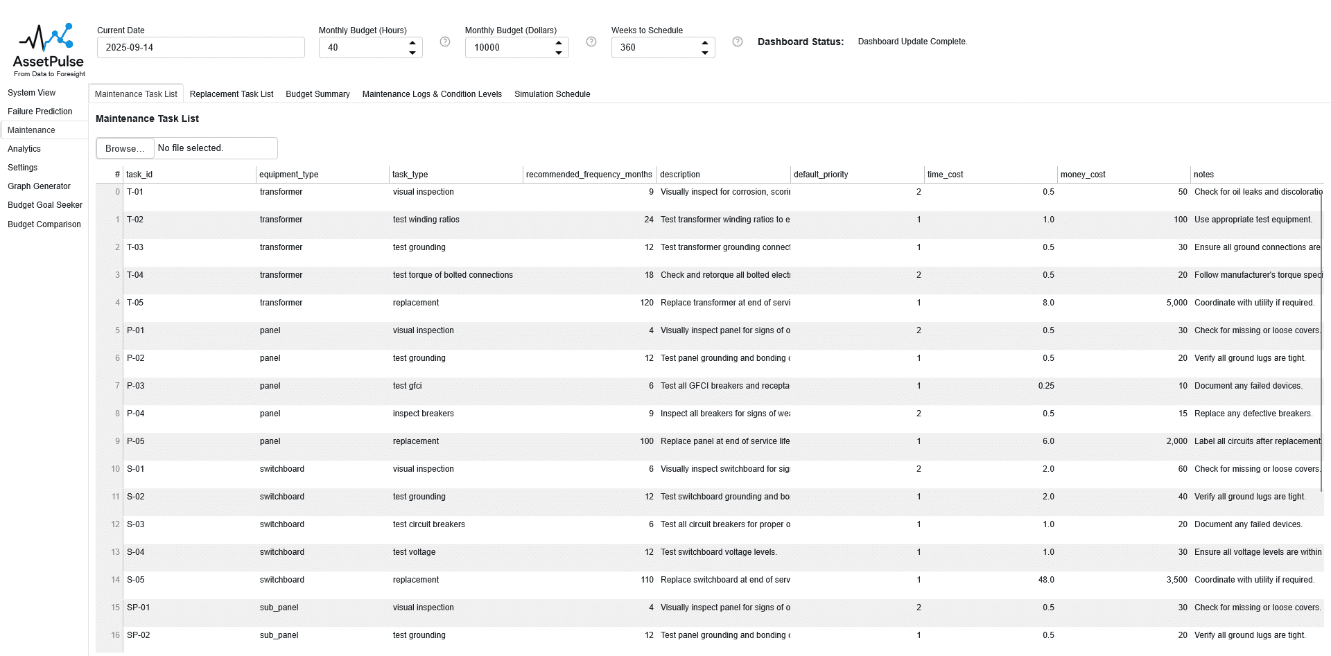
Maintenance Task Templates
Maintenance tasks are defined using a template that specifies the type of task, associated equipment types, frequency, time and money costs, and priority. These template helps standardize maintenance activities across different equipment. The simulation engine uses the uploaded maintenance task template to generate and schedule maintenance tasks for each piece of equipment in the building graph.
When the simulation engine processes maintenance tasks, it generates detailed tasks based on the equipment type and the recommended frequency specified in the template. Each task is linked to a specific equipment node and scheduled accordingly. Tasks are prioritized based on risk score and template priority, with repair and replacement tasks for critical equipment considered before routine maintenance.
For example, a maintenance task template might specify that all “panel” equipment requires a “grounding test” every 12 months with a time cost of 2 hours and a money cost of $150. The simulation engine will create individual grounding test tasks for each panel in the building graph, scheduled based on their installation date and the recommended frequency.
Each month could include a mix of scheduled tasks, executed tasks, and deferred tasks. The scheduled tasks list will show all tasks that were planned for that month, including those that were deferred from previous months. The executed tasks list will show which of those scheduled tasks were actually completed, while the deferred tasks list will indicate which tasks could not be completed due to budget constraints or other factors.
Maintenance Task Template Fields
- task_id
- The unique identifier for the maintenance task. When the tasks for each piece of equipment are generated from the template, this field is concatenated with the equipment ID to ensure uniqueness.
- equipment_type
- The type of equipment this maintenance task applies to (e.g., “panel”, “transformer”).
- task_type
- The category of maintenance task (e.g., “inspection”, “cleaning”, “testing”).
- Repair and replacement tasks are handled separately using the Repair and Replacement Task Templates.
- recommended_frequency_months
- The recommended interval (in months) between recurring maintenance tasks. Tasks will be scheduled based on this frequency starting from the equipment installation date. When a task is deferred, the next occurrence will be scheduled based on the deferral date.
- description
- A brief explanation of the maintenance task’s purpose and activities. This field is optional and can be left blank.
- default_priority
- The default priority level assigned to the task for scheduling and resource allocation. Lower numbers indicate higher priority. Tasks with the same priority are scheduled based on the node’s risk score.
- time_cost
- Estimated time required to complete the task (in hours).
- money_cost
- Estimated monetary cost to perform the task (in dollars).
- notes
- Additional information or special instructions related to the task. This field is optional and can be left blank.
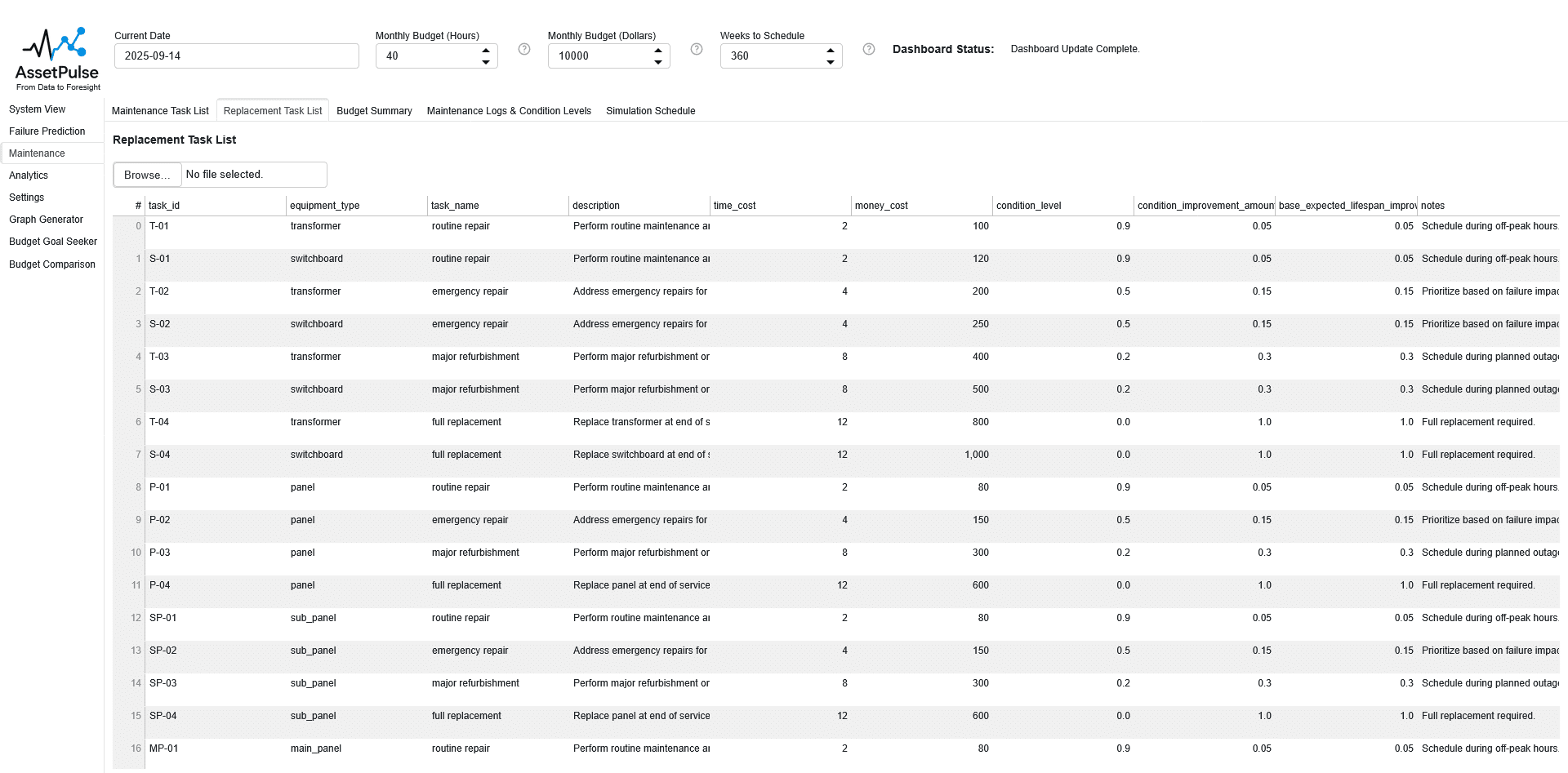
Repair and Replacement Task Templates
Repair and replacement tasks are defined using templates that specify the type of task, associated equipment types, time and money costs, and condition thresholds. The simulation engine uses the uploaded repair and replacement task templates to generate and schedule these tasks for equipment flagged for repair or replacement based on RUL and condition.
Repair and replacement tasks are prioritized before routine maintenance tasks and are scheduled when equipment is flagged for repair or replacement due to low RUL or poor condition, subject to budget constraints. These tasks can be deferred if budgets do not allow for immediate action, but they will be tracked until completed.
If multiple pieces of equipment are flagged for repair or replacement in the same month, the simulation engine will prioritize these tasks based on risk level and available budget. This can cause scenarios where for many consecutive months, all available budget is consumed by repair and replacement tasks, leading to deferral of routine maintenance tasks. This behavior reflects real-world scenarios where critical repairs and replacements take precedence over regular upkeep.
Repair and Replacement Task Template Fields
- task_id
- The unique identifier for the repair or replacement task. When the tasks for each piece of equipment are generated from the template, this field is concatenated with the equipment ID to ensure uniqueness.
- equipment_type
- The type of equipment this repair or replacement task applies to (e.g., “panel”, “transformer”).
- task_name
- The name of the repair or replacement task (e.g., “replace breaker”, “repair transformer”).
- description
- A brief explanation of the task’s purpose and activities. This field is optional and can be left blank.
- time_cost
- Estimated time required to complete the task (in hours).
- money_cost
- Estimated monetary cost to perform the task (in dollars).
- condition_level
- The condition threshold (0.0 to 1.0) below which the equipment is flagged for this task. For example, a value of 0.3 means the task is triggered when the equipment condition falls below 30%.
- condition_improvement_amount
- The amount by which the equipment’s condition improves after completing the task (e.g., 0.05 means a piece of equipment that is at 0.85 will improve to 0.90).
- base_expected_lifespan_improvement_percentage
- The percentage increase in expected lifespan after completing the task (e.g., 0.10 means a piece of equipment with a baseline expected lifespan of 20 years will increase to 22 years).
- notes
- Additional information or special instructions related to the task. This field is optional and can be left blank.
Budget Parameters
The simulation engine allows users to define monthly budgets for maintenance tasks, including time and money constraints. These budgets influence which tasks can be executed each month, with higher-priority tasks being scheduled first. Users can also enable budget rollover, allowing unused budget from one month to carry over to the next.
We see these as the key parameters for getting useful simulation results. In the real world, budgets may vary month to month, and our simulation engine and analysis tools can allow operators to explore the impact of different budget scenarios on asset management outcomes.
The budget parameters are:
- Monthly Budget (Hours)
- Set the monthly hour budget for maintenance tasks. This limits how many maintenance activities can be performed each month.
- Monthly Budget (Dollars)
- Set the monthly dollar budget for maintenance tasks. This limits the total cost of maintenance activities each month.
- Enable Budget Rollover (Boolean)
- Allow unused budget from one month to carry over to the next, providing flexibility in scheduling. To best simulate real-world scenarios, we recommend lowering the monthly time and money budgets if this option is enabled, to prevent unrealistic accumulation of budget over time. We recommend not enabling this option if the goal is to simulate a strict monthly budget scenario, as indefinite budget accumulation is not realistic.
- Weeks to Schedule Ahead
- Set how many weeks past the current date the maintenance scheduler should plan tasks. The simulation will always simulate between the system’s construction date and the current date.
Input Reflections
In reality these tasks would be determined by the specific equipment and manufacturer recommendations. For the purposes of this simulation, we use generic maintenance, repair/replacement tasks that apply to broad equipment categories. Users can customize both maintenance and repair/replacement task templates to better reflect their specific asset management practices.
Increased simulation accuracy may even require more granular equipment types in the graph to ensure that the correct tasks are applied. For example, if a user wants to differentiate between different sizes or models of transformers, they may need to create separate equipment types in the graph (e.g., “transformer_small”, “transformer_large”) and define corresponding tasks for each type. This allows for more precise control over maintenance and repair/replacement strategies based on the specific characteristics of the equipment.
We see this as an area for future improvement, where future researchers can explore more detailed equipment classifications and their impact on asset management strategies, based on real-world data and practices.
Simulation Logic
Once the user sets the RUL simulation parameters, the simulation engine uses these values to calculate the Remaining Useful Life (RUL) for each piece of equipment in the building graph over each month of the simulation period. The process involves:
- Task Generation
- Maintenance tasks are generated from the building graph and generic/replacement task templates, with each task linked to a specific equipment node and scheduled based on installation date and recommended frequency.
- Initialize RUL Parameters
- The simulation engine loads user-defined RUL parameters, including equipment lifespans, failure rates, aging factors, maintenance impact factors, and risk thresholds.
- Iterate Over Simulation Period
- For each month in the simulation period, the engine updates the current date and recalculates RUL for all equipment nodes in the graph.
- Calculate RUL for Each Node
- For each equipment node, determine its installation date, expected lifespan, and operating history.
- Compute the baseline RUL as the difference between expected lifespan and operating time.
- Adjust RUL for deferred maintenance tasks using the task deferment factor and overdue impact multiplier.
- Apply aging acceleration and cap aging impact using the aging acceleration factor and maximum aging multiplier.
- Adjust RUL based on current equipment condition, ensuring a minimum condition factor is applied.
- Ensure RUL does not fall below a minimum ratio of expected lifespan.
- Assess Risk Level and Failure Probability
- For each node, calculate annual failure probability using base failure rates, aging factor, and condition.
- Assign a risk level (LOW, MEDIUM, HIGH, CRITICAL) based on RUL thresholds and condition.
- Flag equipment for replacement if risk level meets the replacement threshold.
- Update Graph Attributes
- Store calculated RUL (in days and years), risk level, failure probability, and condition history in each node’s attributes.
- Optionally, print warnings for critically low RUL or high failure risk if enabled.
- Maintenance Task Scheduling and Execution
- For each month, the simulation engine generates a prioritized schedule of maintenance tasks for equipment nodes, using generic and replacement task templates.
- Tasks are scheduled based on recommended frequency, equipment installation date, and current risk level.
- Each task includes time and money cost estimates, priority, and status (pending, in progress, complete).
- Monthly budgets for time and money are enforced; tasks exceeding the budget are deferred to future months. If budget rollover is enabled, unused budget carries forward.
- Synthetic maintenance logs can be generated for each node to simulate observed condition changes, using randomized condition values and log entries.
- Synthetic logs include a date, condition rating (0.0–1.0), and description.
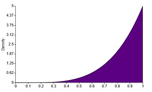
- Synthetic logs use a random seed for reproducibility and employ a beta distribution to model realistic condition changes:
new_condition = round(random.betavariate(alpha=5, beta=1) * current_condition, 1)
- Replacement tasks are triggered for equipment with low condition or high risk, prioritized before routine tasks.
- For each executed task, the equipment node’s condition is improved, and the maintenance history is updated. Deferred tasks increase the deferred count, impacting future RUL calculations.
The beta distribution function is shown below, with alpha=5 and beta=1, which skews the distribution towards higher condition values, simulating realistic maintenance outcomes:
- Reporting and Analysis
- After each month, the simulation engine records the scheduled, executed, and deferred tasks, maintenance logs, and replacement actions.
- The updated graph state (including RUL, condition, and risk) is saved for each month, enabling time-series analysis.
- System-wide summaries include total tasks scheduled, executed, deferred, and replaced, as well as budget utilization and risk distribution.
- Detailed component-level metrics and maintenance histories are available for further analysis and visualization.
Simulation Output
The simulation engine outputs each month’s RUL and risk assessment results in a dictionary format, with keys representing the month (e.g., “2023-01”). Each month’s record contains:
- Month identifier (e.g., “2023-01”)
- List of tasks scheduled for the month
- This list includes all tasks that were scheduled, regardless of whether they end up executed or deferred. Tasks that were deferred from previous months will also appear in this list, since they will need to be tracked until they are completed.
- rollover_time_budget
- Unused time budget carried over from previous month (if rollover is enabled)
- rollover_money_budget
- Unused money budget carried over from previous month (if rollover is enabled)
- time_budget
- Total time budget allocated for the month
- This is added to the rollover_time_budget to determine the total time available for maintenance tasks in the month.
- The time budget is refreshed at the start of each month based on user settings.
- money_budget
- Total money budget allocated for the month
- This is added to the rollover_money_budget to determine the total money available for maintenance tasks in the month.
- The money budget is refreshed at the start of each month based on user settings.
- graph
- The updated building graph with current RUL, risk levels, and condition for all equipment nodes, other metadata, and structural information, enabling detailed time-series analysis and visualization.
- This graph reflects all changes made during the month, including executed maintenance tasks, condition updates, and any replacements.
- The graph is stored in NetworkX format for compatibility with various analysis and visualization tools.
- executed_tasks
- List of tasks that were successfully executed during the month, including details such as task type, associated equipment, time and money costs, and completion status.
- deferred_tasks
- List of tasks that were deferred during the month, including reasons for deferral and any impacts on future scheduling.
- maintenance_logs
- Records of all maintenance activities performed during the month, including inspections, repairs, and replacements.
- These are synthetic logs generated to simulate real-world maintenance records if synthetic log generation is enabled.
- replacement_tasks_executed
- List of equipment replacement tasks completed during the month, with details on replaced components and associated costs.
- replacement_tasks_not_executed
- List of planned replacement tasks that were not executed, including reasons.
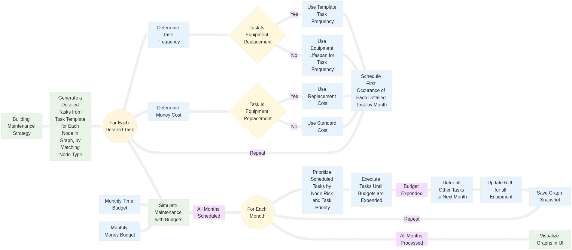
Remaining Useful Life (RUL) Simulation Diagram
The following diagram illustrates the components and workflow of the Remaining Useful Life (RUL) Simulation, which is responsible for simulating maintenance scheduling, risk assessment, and RUL calculations over time.
Simulation Analysis and Visualization
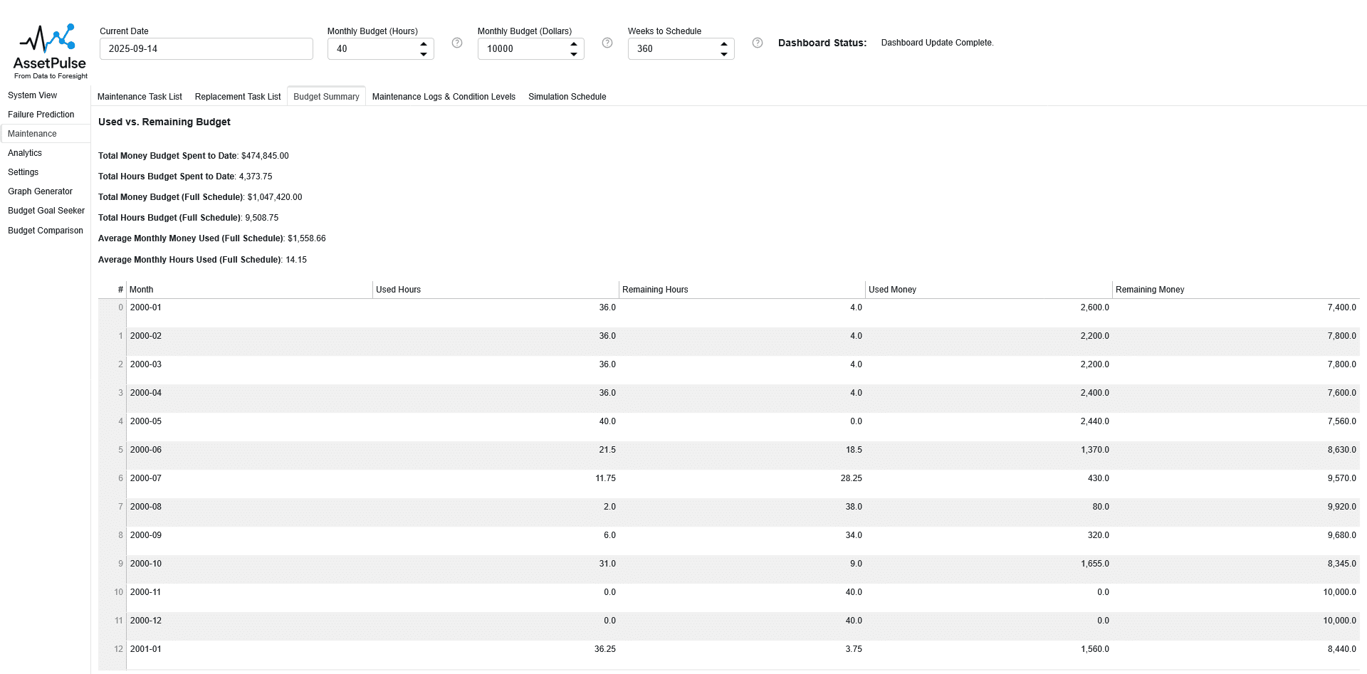
Budget Summary
After all scenarios are simulated, the tool generates a summary table displaying the money and time budgets for each scenario, allowing users to quickly compare the different budget allocations. The following data is shown in the summary table:
The following data is shown in the summary table:
- Total Money Budget Spent to Date: This is the cumulative amount of money spent on maintenance tasks across all months simulated up to the current date.
- Total Hours Budget Spent to Date: This is the cumulative number of hours spent on maintenance tasks across all months simulated up to the current date.
- Total Money Budget (Full Schedule): This is the cumulative amount of money spent on maintenance tasks across all months simulated in the full schedule.
- Total Hours Budget (Full Schedule): This is the cumulative number of hours spent on maintenance tasks across all months simulated in the full schedule.
- Average Monthly Money Used (Full Schedule): This is the average amount of money spent per month on maintenance tasks across the full schedule.
- Average Monthly Hours Used (Full Schedule): This is the average number of hours spent per month on maintenance tasks across the full schedule.
An example output is shown below:
- Total Money Budget Spent to Date: $474,845.00
- Total Hours Budget Spent to Date: 4,373.75
- Total Money Budget (Full Schedule): $1,047,420.00
- Total Hours Budget (Full Schedule): 9,508.75
- Average Monthly Money Used (Full Schedule): $1,558.66
- Average Monthly Hours Used (Full Schedule): 14.15
System Health Overview
The system health overview provides a very high-level summary of the overall condition and risk levels of all equipment. An example output is shown below:
Average Condition: 97%
Total Number of Nodes: 40
Risk Levels: LOW: 31 | MEDIUM: 8 | HIGH: 1
Critical Component Overview
The critical component overview highlights the most at-risk equipment in the system, allowing users to quickly identify components that may require immediate attention. An example output is shown below:
Critical Components: 16
- MP0.0
- TR0.0.208.L
- TR0.0.208.R
- TR0.0.208.H
- MP1.0
- TR1.0.208.L
- TR1.0.208.R
- TR1.0.208.H
- MP2.0
- TR2.0.208.L
- TR2.0.208.R
- TR2.0.208.H
- MP3.0
- TR3.0.208.L
- TR3.0.208.R
- TR3.0.208.H
Next 12 Months Overview
The next 12 months overview provides a summary of scheduled maintenance tasks, executed tasks, deferred tasks, and budget utilization for the upcoming year. An example output is shown below:
2025-10:
- Expected Executed Tasks: 7
- Most Critical Expected Task: P-03-MP2.0
- Deferred Tasks: 136
- Most Critical Deferred Task: S-05-MP0.0
2025-11:
- Expected Executed Tasks: 5
- Most Critical Expected Task: P-02-SP0.0.480.R
- Deferred Tasks: 135
- Most Critical Deferred Task: S-05-MP0.0
2025-12:
- Expected Executed Tasks: 6
- Most Critical Expected Task: P-03-SP3.0.480.R
- Deferred Tasks: 134
- Most Critical Deferred Task: S-05-MP0.0
2026-01:
- Expected Executed Tasks: 3
- Most Critical Expected Task: S-03-MP0.0
- Deferred Tasks: 138
- Most Critical Deferred Task: S-05-MP0.0
2026-02:
- Expected Executed Tasks: 9
- Most Critical Expected Task: S-04-MP0.0
- Deferred Tasks: 140
- Most Critical Deferred Task: S-05-MP0.0
2026-03:
- Expected Executed Tasks: 8
- Most Critical Expected Task: P-03-MP3.0
- Deferred Tasks: 135
- Most Critical Deferred Task: S-05-MP0.0
2026-04:
- Expected Executed Tasks: 7
- Most Critical Expected Task: P-02-MP1.0
- Deferred Tasks: 131
- Most Critical Deferred Task: S-05-MP0.0
2026-05:
- Expected Executed Tasks: 8
- Most Critical Expected Task: P-02-MP2.0
- Deferred Tasks: 125
- Most Critical Deferred Task: S-05-MP0.0
2026-06:
- Expected Executed Tasks: 6
- Most Critical Expected Task: P-03-SP3.0.480.R
- Deferred Tasks: 123
- Most Critical Deferred Task: S-05-MP0.0
2026-07:
- Expected Executed Tasks: 2
- Most Critical Expected Task: S-03-MP0.0
- Deferred Tasks: 124
- Most Critical Deferred Task: S-05-MP0.0
2026-08:
- Expected Executed Tasks: 11
- Most Critical Expected Task: P-02-SP1.0.480.H
- Deferred Tasks: 125
- Most Critical Deferred Task: S-05-MP0.0
2026-09:
- Expected Executed Tasks: 8
- Most Critical Expected Task: P-03-MP3.0
- Deferred Tasks: 124
- Most Critical Deferred Task: S-05-MP0.0
Cost Forecast Overview
The cost forecast provides an estimate of the financial resources required to support the planned maintenance activities over the next 12 months. It accounts for expected executed tasks, deferred tasks, and associated time and money costs, enabling informed budgeting and resource allocation decisions. An example output is shown below:
Total Expected Money Cost for Next 12 Months: $1770.0
Total Expected Time Cost for Next 12 Months: 36.0 hours
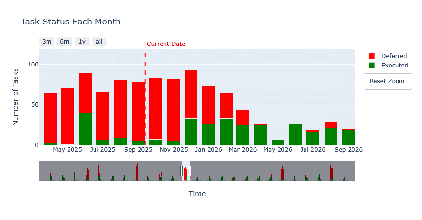
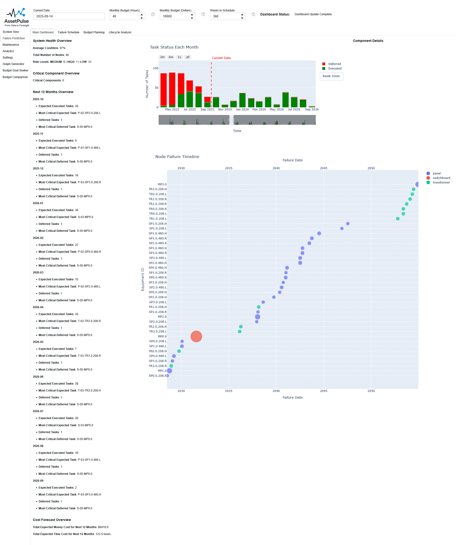
Task Status Each Month Chart
The task status each month chart visualizes the number of executed, and deferred maintenance tasks over the simulation period as a stacked bar chart. This chart helps users understand trends in maintenance activities and identify periods of high deferral or execution rates.
Preset time windows are available for quick selection, including 3 months, 6 months, 12 months, and the full simulation period. Users can also customize the time window by adjusting the timeline slider to focus on specific periods of interest. The default view shows the previous 6 months and the next 12 months.
An example chart is shown below:
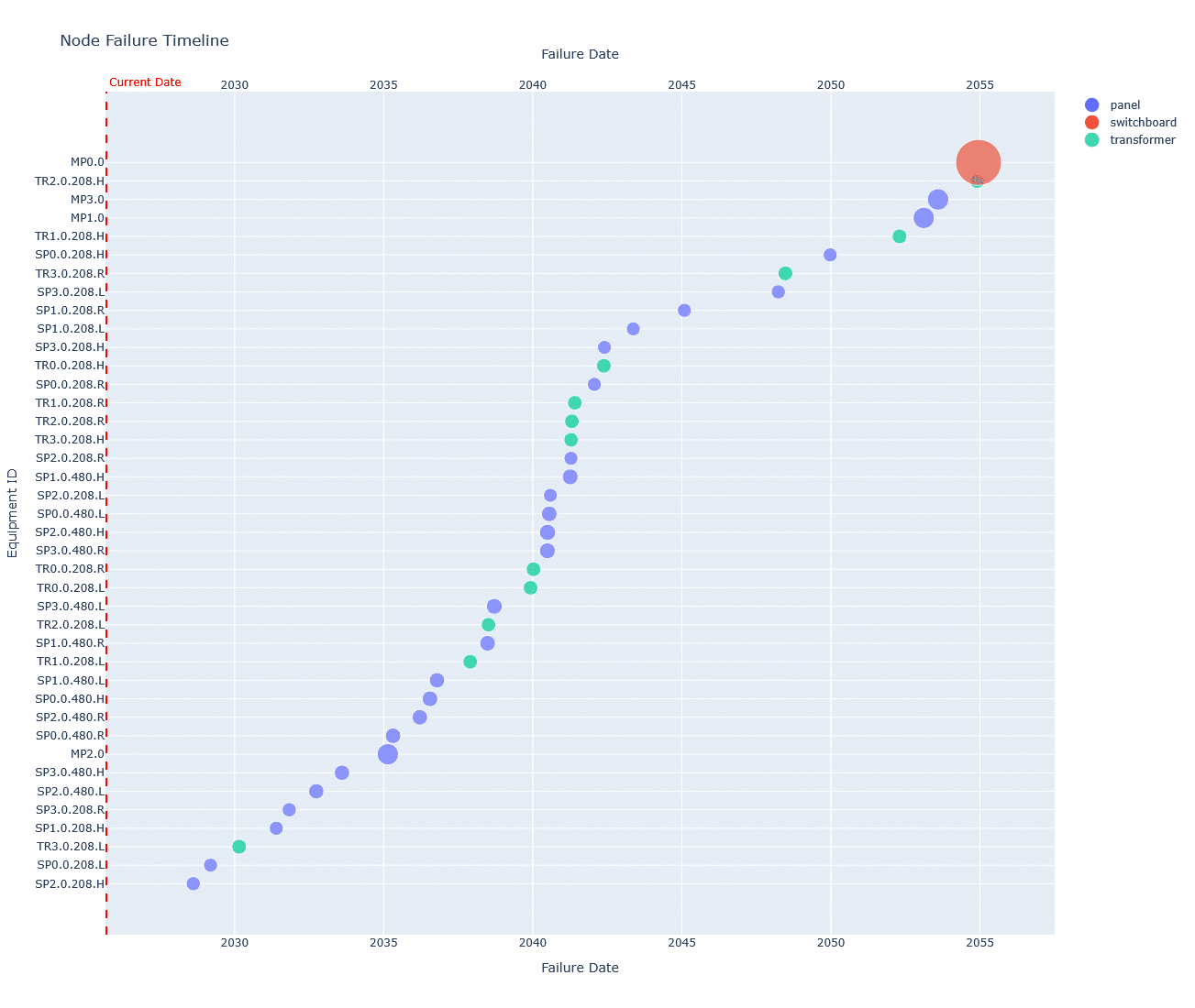
Node Failure Timeline Chart
The node failure timeline chart visualizes the expected failure events of equipment nodes over the simulation period. This chart helps users identify when and which components are likely to fail, supporting proactive maintenance planning and risk mitigation.
The chart is sorted by the node risk score, with higher-risk nodes displayed at the top. Each node is represented by circular markers indicating the expected failure dates. The size of each marker corresponds to the risk level of the node, with larger markers indicating higher risk.
An example chart is shown below:
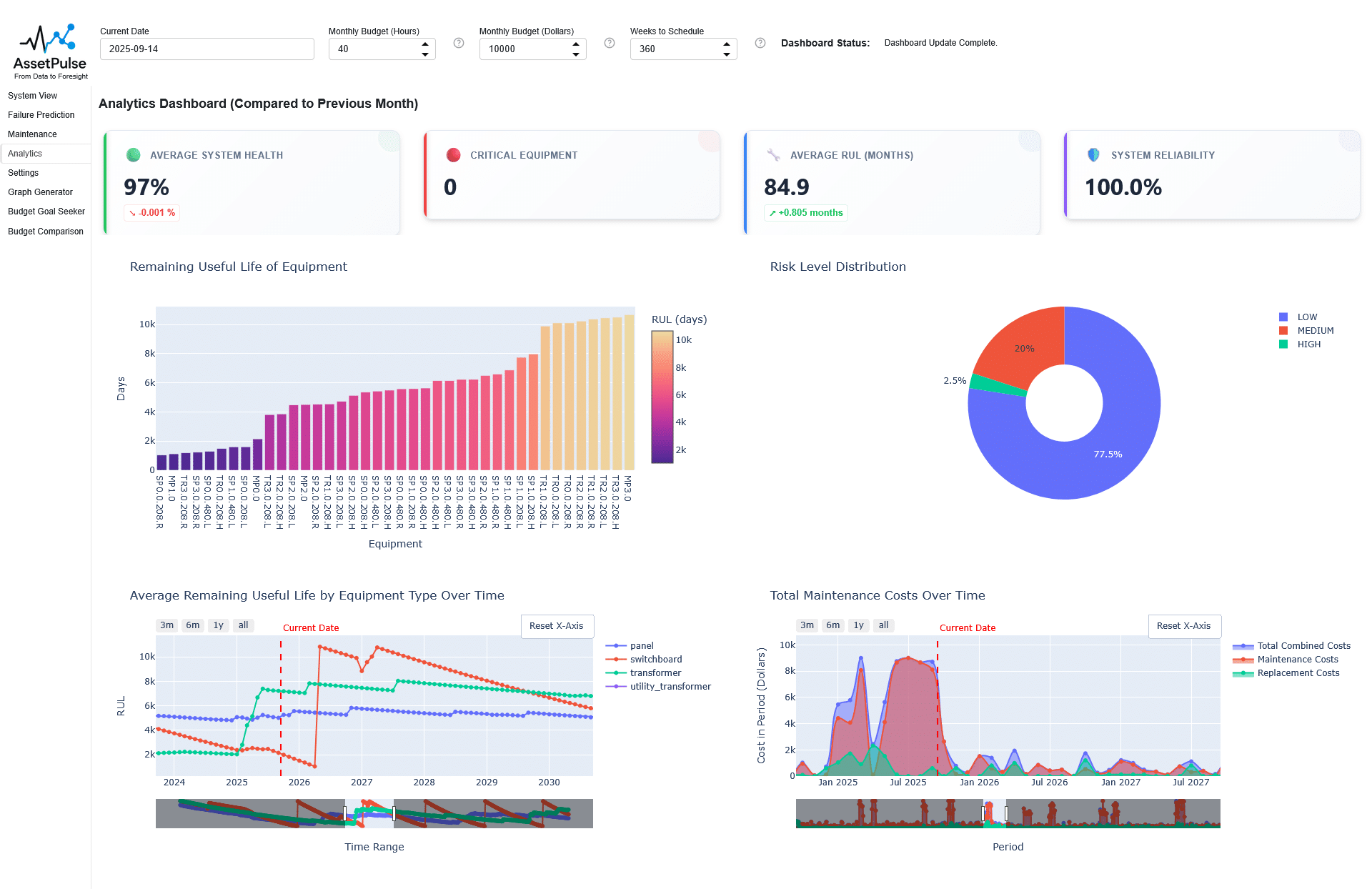
KPI Cards
The KPI cards provide quick access to key performance indicators related to the asset management simulation. These cards display important metrics such as average system health, quantity of critical equipment, average RUL, and system reliability. An example set of KPI cards is shown below:

Remaining Useful Life (RUL) Distribution Chart
The RUL distribution chart visualizes the distribution of Remaining Useful Life (RUL) across all equipment nodes in the system. This chart helps users understand the overall health and longevity of their assets, enabling informed maintenance and replacement planning.
An example chart is shown below:
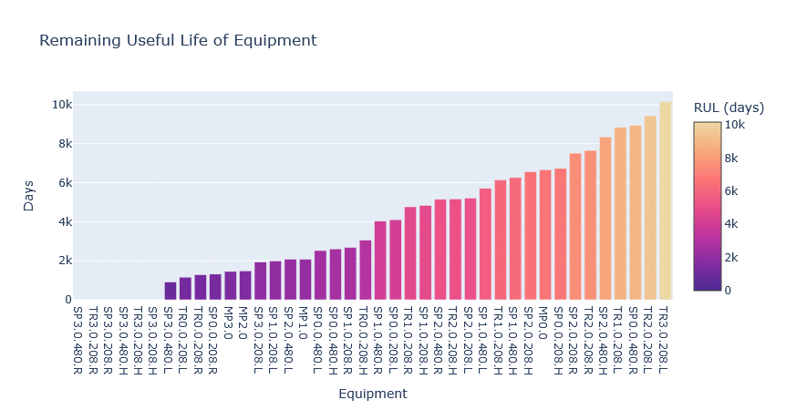
You can see in the example chart that some equipment has a high RUL and is in good condition, while other equipment has a low RUL and may require immediate attention. This should be expected because the simulation will prioritize maintenance tasks based on each node’s risk score and budget constraints, leading to some equipment being fwell-maintained while others may be deferred.
Risk Level Distribution Chart
The risk level distribution chart visualizes the distribution of risk scores across all equipment nodes in the system. This chart helps users identify the proportion of high-risk components, supporting prioritization of maintenance and replacement efforts.
An example chart is shown below:
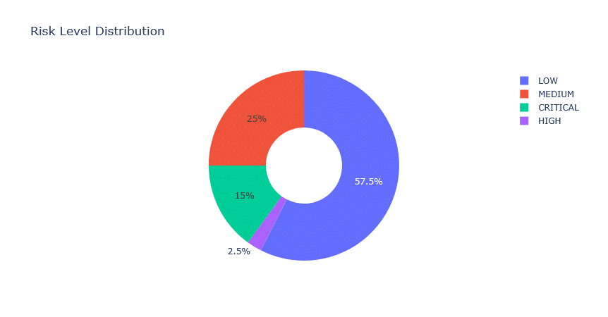
In the example chart, we can see that most equipment is classified as LOW risk, with the rest classified as MEDIUM, HIGH, and CRITICAL risk.
Average Remaining Useful Life by Equipment Type Over Time Chart
The average remaining useful life (RUL) by equipment type over time chart visualizes trends in asset longevity across different categories of equipment. This chart helps users identify which equipment types may require earlier replacement or more frequent maintenance, supporting targeted asset management strategies.
An example chart is shown below:
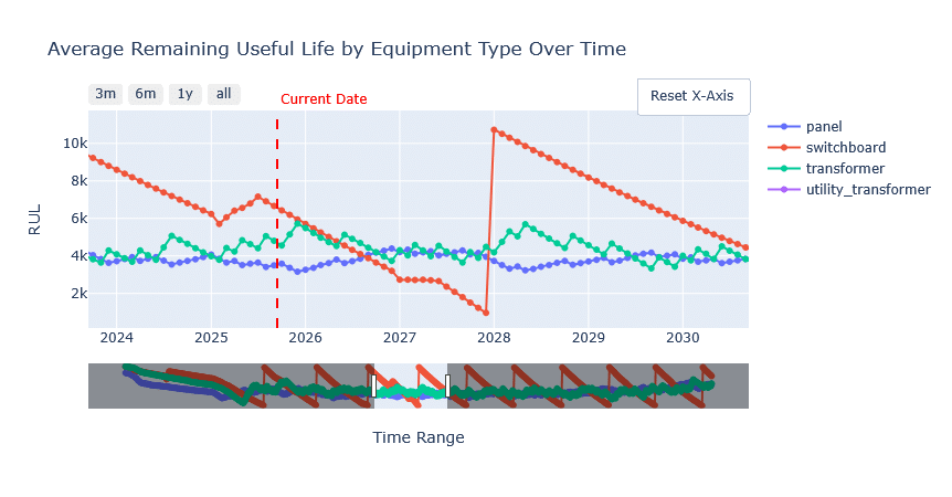
This chart is a key indicator of how well maintenance strategies are preserving the lifespan of different equipment types. The average RUL for each equipment type should decrease over time, reflecting the natural aging and wear of the equipment. However this decrease will be faster if maintenance is regularly deferred due to budget constraints, and conversely, the decrease will be slower if repair and replacement is consistently performed on schedule.
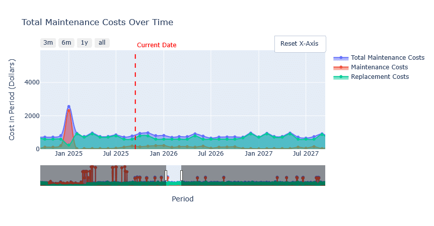
Total Maintenance Cost Over Time Chart
The total maintenance cost over time chart visualizes the cumulative maintenance expenses incurred throughout the simulation period. This chart helps users monitor budget utilization, identify cost trends, and evaluate the financial impact of maintenance strategies.
An example chart is shown below:
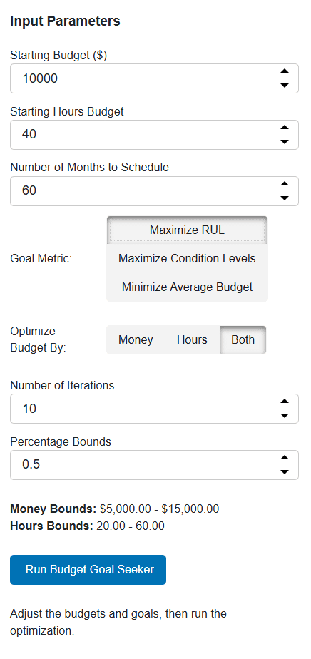
Budget Goal Seeker
The Budget Goal Seeker module enables users to optimize maintenance budgets and resource allocation using an interactive, simulation-driven approach. It allows both single variable and multivariate optimization and visualization to help users identify the best budget strategies for maximizing asset health, condition, or minimizing costs.
Workflow and Logic
- User Inputs:
- Users specify starting budgets for money and hours, the number of months to schedule, optimization goals (e.g., Maximize RUL, Maximize Condition Levels, Minimize Average Budget), and the optimization value (Money, Hours, or Both).
- Additional controls include the number of optimization iterations and percentage bounds for budget search space.
- These bounds define the range within which the optimization algorithm will search for the optimal budget values. For example, if the starting budget is $10,000 and the bounds are set to ±50%, the algorithm will explore budgets between $5,000 and $15,000.
- Users can also select the output metric to evaluate (Average RUL, Average Condition, or Average Budget Used).
- The choice of output metric determines how the optimization algorithm assesses the effectiveness of different budget allocations. If the user selects Average RUL, the algorithm will aim to find budget values that maximize the average remaining useful life of equipment over the simulation period; if Average Condition is selected, it will focus on maximizing the average condition levels of all equipment over the simulation period; and if Average Budget Used is chosen, it will seek to minimize the average budget expenditure each simulated month.
- Optimization Process:
- The system runs a baseline simulation with the initial budgets and records the metric value for the selected goal.
- For single-variable optimization (Money or Hours), the tool uses
scipy.optimize.minimize_scalarto search for the optimal budget within user-defined bounds. - For multivariate optimization (Both), the tool uses
scipy.optimize.minimize(Nelder-Mead) to simultaneously optimize both money and hours budgets. - At each iteration, the simulation engine updates the graph controller with the candidate budgets, runs the RUL simulation, and evaluates the chosen metric (average RUL, condition, or budget usage).
- All iterations and results are logged for analysis and visualization in real-time, as iterations are completed. This allows users to see the optimization progress and understand how different budget allocations impact the selected metric.
- Visualization:
- Results are visualized using Plotly charts with up to three y-axes: Money Budget, Hours Budget, and the output metric (e.g., Average RUL).
- The UI displays the optimization progress, bounds, and final results, allowing users to compare baseline, iterative, and optimal outcomes.
- DataFrames and markdown panes provide tabular and textual summaries of the optimization process.
- UI Integration:
- The Panel-based UI presents all controls, results, and charts in a responsive layout.
- Users can adjust inputs and rerun the optimization to explore different scenarios and strategies.
- The system caches results and visualizations for seamless interaction and review.
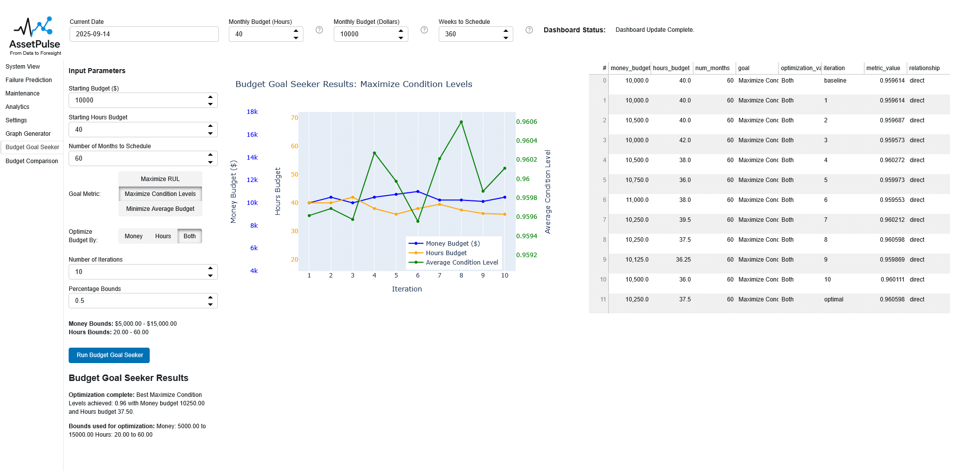
The final graph is shown below:
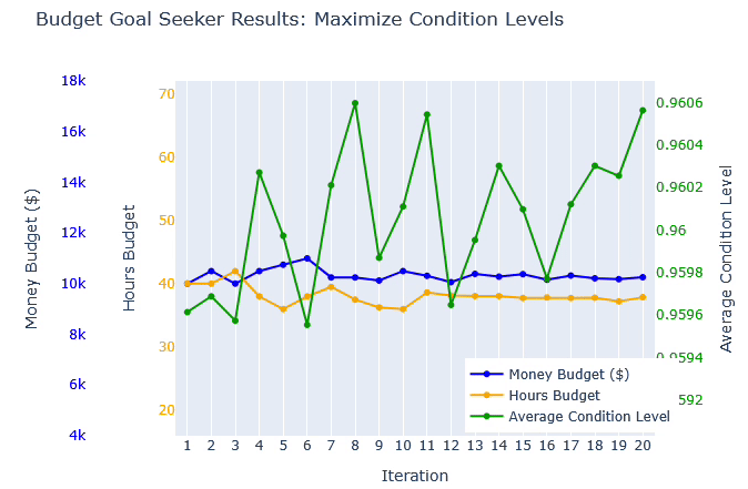
You can see in this example that the relationship between budget and average condition level is not linear, and there are diminishing returns as budgets increase. This highlights the importance of finding an optimal budget that balances cost with asset health outcomes.
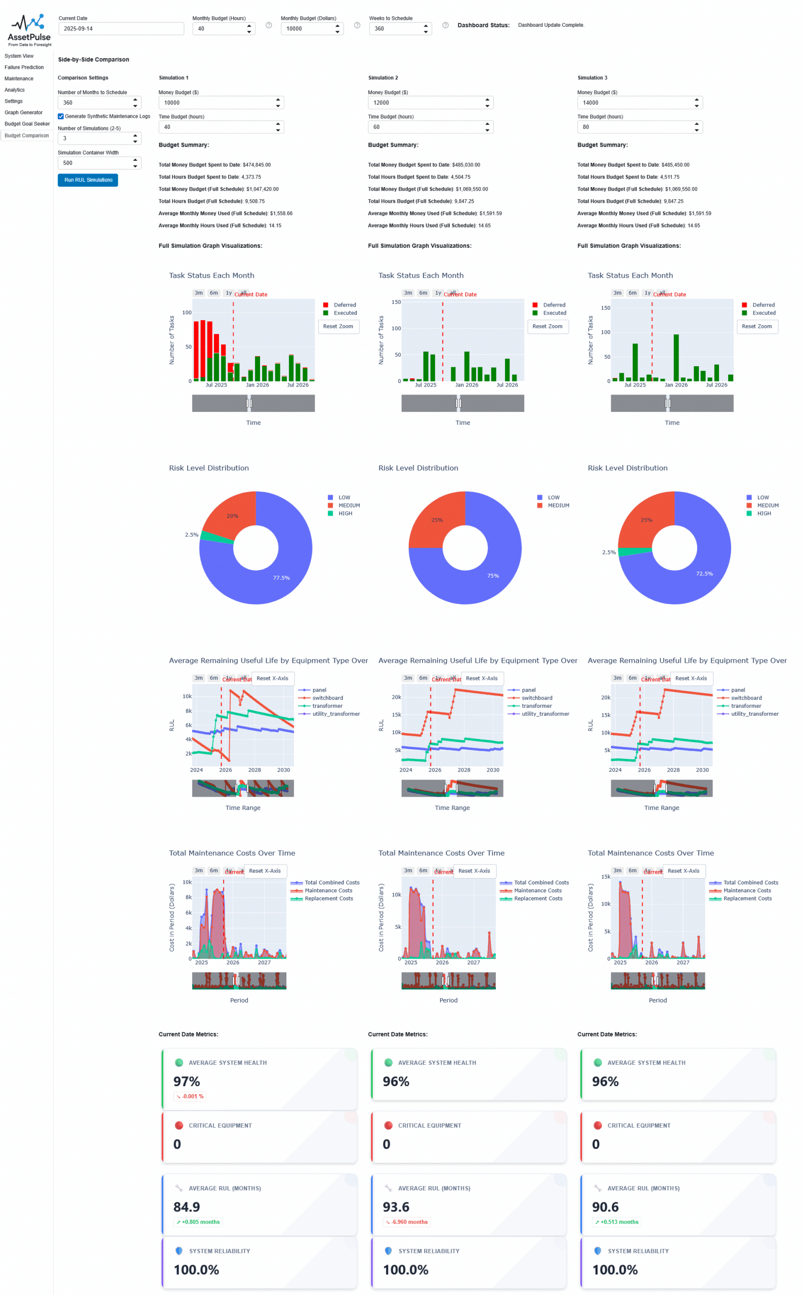
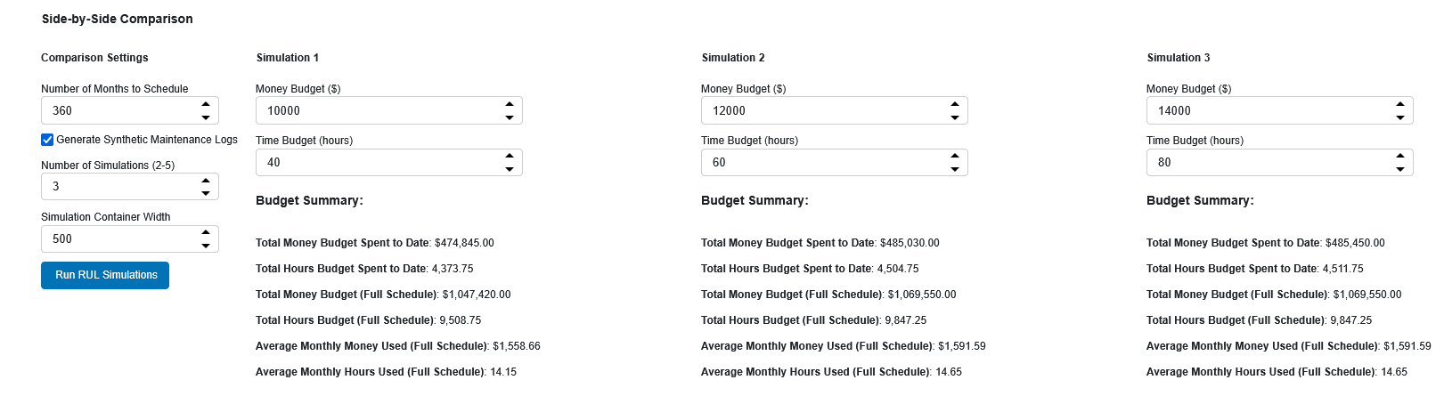
Budget Comparison Tool
The Budget Comparison Tool enables users to run multiple maintenance budget scenarios in parallel and compare their outcomes side-by-side using a consistent building graph and simulation logic. This interactive module is designed to help users understand how different budget allocations affect key performance indicators (KPIs) such as average Remaining Useful Life (RUL), average condition, total maintenance cost, and task execution rates.
Workflow and Logic
- User Inputs:
- Users specify the number of scenarios to compare (between 2 and 5), the number of months to schedule, and whether to generate synthetic maintenance logs for each simulation.
- For each scenario, users can adjust the money and time budgets using input widgets. Default budgets are offset for each scenario to facilitate comparison.
- Simulation Execution:
- For each scenario, the tool creates a copy of the building graph and simulation controller, sets the specified budgets, and runs the RUL simulation for the chosen period.
- The simulation engine updates the graph with the new budget values and executes the maintenance scheduling, risk assessment, and RUL calculations for each month.
- Budget Summary
- For each scenario, the tool generates a budget summary table that is identical to the one described in the Simulation Analysis and Visualization section. This table includes:
- Total Money Budget Spent to Date
- Total Hours Budget Spent to Date
- Total Money Budget (Full Schedule)
- Total Hours Budget (Full Schedule)
- Average Monthly Money Used (Full Schedule)
- Average Monthly Hours Used (Full Schedule)
- For each scenario, the tool generates a budget summary table that is identical to the one described in the Simulation Analysis and Visualization section. This table includes:
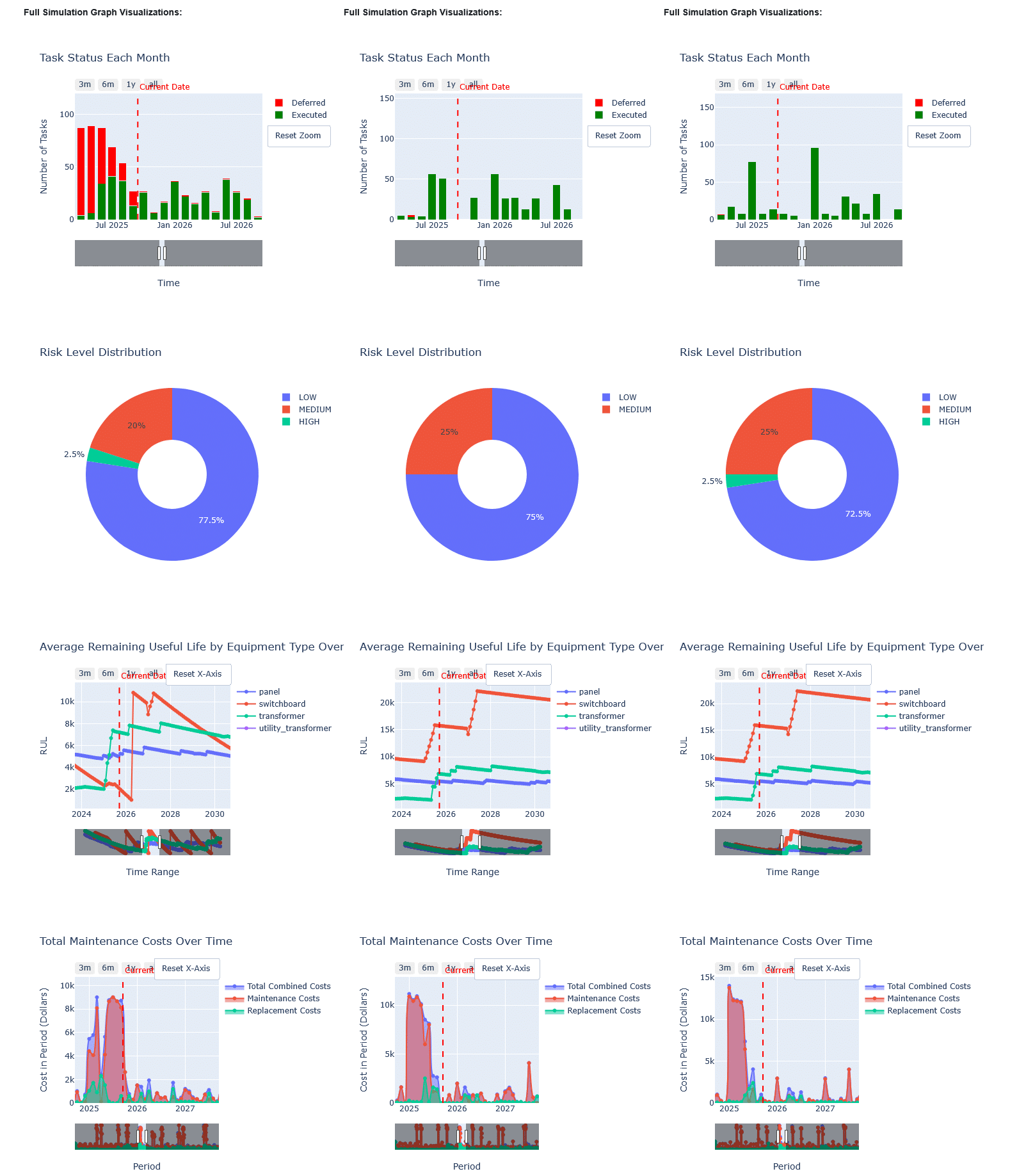
- Visualization and Output:
- For each scenario, the following charts and visualizations are generated:
- Task Status Each Month: Stacked bar chart showing executed and deferred tasks over time.
- Risk Level Distribution Pie Chart: Shows the proportion of equipment at each risk level (LOW, MEDIUM, HIGH, CRITICAL).
- Average RUL by Equipment Type Over Time: Line chart tracking average RUL for each equipment type across the simulation period.
- Total Maintenance Cost Over Time: Line chart showing cumulative maintenance costs for each scenario.
- For each scenario, the following charts and visualizations are generated:
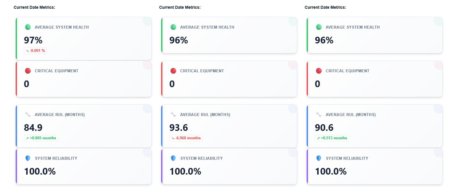
- KPI Calculation:
- After each simulation, the tool calculates and displays key metrics:
- Average System Health: The mean condition of all equipment nodes after the simulation period.
- Critical Equipment Count: The number of equipment nodes classified as ‘CRITICAL’ risk level.
- Average RUL (Months): The mean remaining useful life of all equipment, converted to months.
- System Reliability: The percentage of non-critical equipment nodes, representing overall system reliability.
- After each simulation, the tool calculates and displays key metrics:
Analysis and Insights
Results, KPI cards, and charts are displayed side-by-side for direct comparison between different budget scenarios.
By comparing scenarios with different budget allocations, users can identify trade-offs between cost, system health, reliability, and risk. The tool supports rapid iteration, allowing users to adjust budgets and immediately see the impact on KPIs and visualizations.
For example, users might find that a moderate increase in budget leads to significant improvements in average RUL and system reliability, while further increases yield diminishing returns. Alternatively, users may discover that the current date shows positive metrics, but the overall costs in the past months were very high, indicating an unsustainable maintenance strategy.
Related Work
Literature Review
We conducted a literature review to identify existing tools and frameworks related to asset management, focusing on their capabilities, limitations, and relevance to our project. The review highlighted the need for a comprehensive simulation tool that integrates graph-based modeling, synthetic data generation, and interactive visualization to support asset management decision-making.
Some research has explored the use of graph based modeling for electrical systems, such as (Cuffe and Keane 2017) who developed graph-based visualization techniques for circuit-level electrical power systems using graph theory. (Liu et al. 2023) reviewed the application of graph neural networks (GNNs) in utility-scale power electronics, for example modeling power grid accident behaviors. (Lendak et al. 2010) proposed algorithms for generating one-line diagrams of electrical power systems using genetic algorithms. (Liao et al. 2022) provides a review of graph neural networks (GNNs) and their applications in specifically utility-level power systems, including fault prediction, time-series forecasing, and power flow calculation. (Miao et al. 2020) applied knowledge graphs to power communcation networks. However, these studies primarily focus on high-voltage power systems or very low-voltage systems and do not address the specific needs of low-voltage building electrical systems or asset management.
Knowledges are particularly of interest, as they provide a structured way to represent and reason about complex systems. (Pauwels, Costin, and Rasmussen 2022) provides a review of knowledge graphs and their applications in the built environment. Much of this work focuses on ontology development rather than simulation or asset management. Our simulation relies on a building’s knowledge graph to represent the relationships between assets and their attributes, enabling more accurate modeling of asset behaviors and interactions.
Existing Tools and Frameworks
Several existing tools and frameworks address various aspects of asset management, including maintenance scheduling, risk assessment, and budget optimization. However, many of these tools lack the comprehensive integration of graph-based modeling, synthetic data generation, and interactive visualization that AssetPulse offers.
- IBM Maximo
- Enterprise Asset Management (EAM) platform.
- Supports asset lifecycle, preventive/reactive maintenance, risk management, and budget planning.
- Includes some predictive analytics and scheduling, but not graph-based simulation.
- SAP Intelligent Asset Management
- Asset network, predictive maintenance, and risk management.
- Integrates with business rules and scenario planning.
- Focuses on enterprise integration, not custom graph/network simulation.
- Uptake, Fiix, and other CMMS platforms
- Computerized Maintenance Management Systems (CMMS) with asset tracking, maintenance scheduling, and analytics.
- Some offer risk scoring and scenario analysis, but typically not network/graph-based modeling.
- Bentley AssetWise
- Infrastructure asset management with network modeling.
- Supports lifecycle, risk, and maintenance planning for large infrastructure.
- More focused on civil/utility networks than building systems.
Key differentiators of AssetPulse:
- Explicit graph/network modeling of building systems.
- Automated business rule enforcement for budget, risk, and maintenance.
- Scenario simulation, analysis and interactive visualization.
- Customizable for complex infrastructure, not just standard asset lists.
Future Work
Future enhancements to AssetPulse could include:
Using real-world asset history and maintenance data to determine accurate simulation parameters, refine simulation logic, and validate synthetic data generation.
Purpose: Improve the accuracy and reliability of simulation results.
Enhancements:
- Build connectors to import CMMS (Computerized Maintenance Management System) and BMS (Building Management System) data.
- Validate synthetic data generation models by comparing their predictions against historical failure/maintenance records.
- Use historical data to fine-tune degradation curves, failure probabilities, and RUL adjustment factors.
- Implement statistical dashboards comparing simulated vs. actual maintenance outcomes.
Expand beyond the electrical discipline to all disciplines and tailor functionality to their specifics
Purpose: Create a comprehensive, multi-domain digital twin for holistic asset management.
Enhancements:
- Extend beyond electrical to include mechanical, plumbing, structural, architectural, fire safety, IT, transportation, and sustainability systems.
- Model cross-discipline dependencies (e.g., structural changes affecting MEP layouts or fire safety zones).
- Simulate cascading impacts across disciplines for risk forecasting and lifecycle planning.
- Provide unified visualization and reporting to compare multi-system trade-offs in a single interface.
- Enable integrated decision-making workflows where maintenance, upgrades, or retrofits can be evaluated for their effects across all building systems.
Integrate IFC/BIM input workflow for automated graph generation and add a 3D viewer for interactive model review and FM queries.
Purpose: Streamline graph generation and improve spatial context.
Enhancements:
- Parse IFC or Revit files to automatically create system graphs, including risers, transformers, and loads.
- Integrate open-source BIM libraries (e.g., IfcOpenShell) for data extraction.
- Add a 3D WebGL-based viewer (e.g., using Fragments) for interactive model exploration.
- Enable FM queries (e.g., “Show all switchboards on Floor 3” or “Highlight transformers older than 10 years”).
- Provide side-by-side 2D graph and 3D model linking—selecting a node in one highlights it in the other.
Incorporating more complex asset interactions and dependencies in the graph model to better simulate real-world scenarios.
Purpose: More realistic simulations and risk propagation.
Enhancements:
- Support cascading failures (e.g., transformer failure causing downstream loads to degrade faster).
- Add dependency weights for probabilistic risk transfer between nodes.
- Model shared resources (e.g., backup generators supplying multiple risers) and redundancy logic.
- Allow asset condition to affect energy efficiency or operating cost in simulations.
Incorporate remodeling and expansion scenarios to simulate changes in building systems over time.
Purpose: Plan for future modifications and system growth.
Enhancements:
- Add a scenario editor to “clone” a baseline graph and apply remodeling actions
- Simulate impacts on risk, maintenance cost, and asset lifespan after system expansions.
- Incorporate construction timelines and downtime effects on maintenance strategies.
- Visualize before-and-after states in both 2D and 3D views.
Integrate machine learning techniques to predict failures and optimize maintenance schedules based on historical data.
Purpose: Move beyond static rules toward data-driven forecasting.
Enhancements:
- Use supervised learning on historical maintenance and failure records to predict time-to-failure for components.
- Train models to optimize maintenance schedules for minimal cost and risk.
- Use clustering to identify patterns in similar assets across portfolios.
- Implement anomaly detection for sensor streams (flagging early warning signs of failure).
- Provide explainable AI features to communicate why a prediction was made.
Expand the user interface to include more advanced visualization and reporting features, enabling deeper insights into asset management strategies.
Purpose: Enhance decision-making with rich, interactive insights.
Enhancements:
- Add multi-year cost and risk trend charts with drill-down to individual systems.
- Develop risk heatmaps and Sankey diagrams showing resource flows and dependencies.
- Provide PDF/Excel export of simulation results with customizable templates.
Expand the user interface to include more advanced system graph interaction and editing capabilities, allowing users to modify the building graph directly within the application.
Purpose: Improve usability for facility managers and engineers.
Enhancements:
- Allow drag-and-drop graph editing within the browser (e.g., adding/deleting equipment, re-routing connections).
- Support undo/redo history for safe experimentation.
- Enable versioning of system graphs (track changes over time).
- Add context-sensitive menus on nodes for editing properties or linking documents/specs.
- Auto-align and auto-layout options to maintain clean graph visuals after edits.
Incorporate real-time data integration from building management systems (BMS) or Internet of Things (IoT) sensors to inform RUL calculations and maintenance scheduling.
Purpose: Enable predictive maintenance and live system monitoring.
Enhancements:
- Connect to IoT platforms for streaming sensor data.
- Dynamically update RUL calculations as new readings arrive (e.g., temperature spikes reducing lifespan).
- Display live health indicators and risk levels on the graph.
- Trigger alerts or simulations automatically when conditions exceed thresholds.
- Provide an API to ingest external predictive signals.
Develop a collaborative platform where multiple users can work on the same asset management scenarios, sharing insights and strategies.
Purpose: Support multi-user workflows for portfolio-level asset management.
Enhancements:
- Implement user accounts with role-based permissions (e.g., admin, engineer, analyst).
- Add shared scenario editing and commenting tools.
- Enable real-time co-editing of graphs with WebSocket synchronization.
- Maintain a changelog and version history for accountability.
- Provide secure cloud storage for simulation results and configuration files.
References
Cuffe, Paul, and Andrew Keane. 2017. “Visualizing the Electrical Structure of Power Systems.”IEEE Systems Journal 11 (3): 1810–21. https://doi.org/10.1109/JSYST.2015.2427994.
Lendak, Imre, Aleksandar Erdeljan, Darko Capko, and Srdan Vukmirovic. 2010. “Algorithms in Electric Power System One-Line Diagram Creation.” In 2010 IEEE International Conference on Systems, Man and Cybernetics, 2867–73. Istanbul, Turkey: IEEE. https://doi.org/10.1109/ICSMC.2010.5641927.
Liao, Wenlong, Birgitte Bak-Jensen, Jayakrishnan Radhakrishna Pillai, Yuelong Wang, and Yusen Wang. 2022. “A Review of Graph Neural Networks and Their Applications in Power Systems.”Journal of Modern Power Systems and Clean Energy 10 (2): 345–60. https://doi.org/10.35833/MPCE.2021.000058.
Liu, Rui, Rong Fu, Kang Xu, Xuanzhe Shi, and Xiaoning Ren. 2023. “A Review of Knowledge Graph-Based Reasoning Technology in the Operation of Power Systems.”Applied Sciences 13 (7): 4357. https://doi.org/10.3390/app13074357.
Miao, Weiwei, Haiyang Wu, Peng Chen, and Jiangping Jing. 2020. “Intelligent Auxiliary Operation and Maintenance System of Power Communication Network Based on Knowledge Graph.”Journal of Physics: Conference Series 1684 (1): 012105. https://doi.org/10.1088/1742-6596/1684/1/012105.
Pauwels, Pieter, Aaron Costin, and Mads Holten Rasmussen. 2022. “Knowledge Graphs and Linked Data for the Built Environment.” In Industry 4.0 for the Built Environment, edited by Marzia Bolpagni, Rui Gavina, and Diogo Ribeiro, 20:157–83. Structural Integrity. Cham: Springer International Publishing. https://doi.org/10.1007/978-3-030-82430-3_7.
Appendix A: Example Test Data: Simple Building
The following parameters were used to generate a simple building for testing and validation of the AssetPulse simulation tool:
- Construction Year: 2000
- Total Load: 200 kW
- Building Length: 20 m
- Building Width: 20 m
- Number of Floors: 1
- Floor Height: 3.5 m
- Cluster Strength: 0.95
- Random Seed: 42
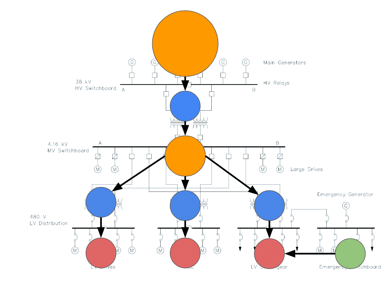
Example Generated Building Graph
Types of Nodes
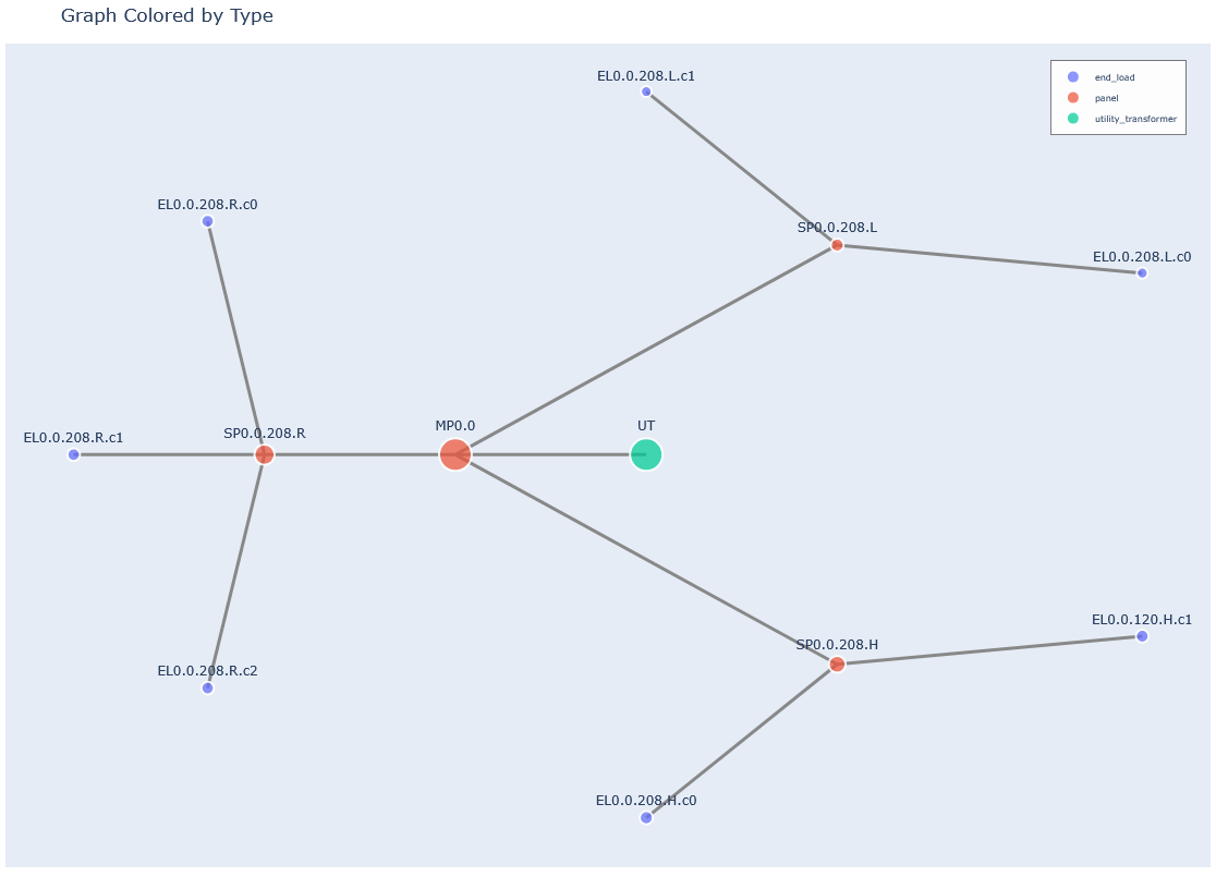
Risk Levels
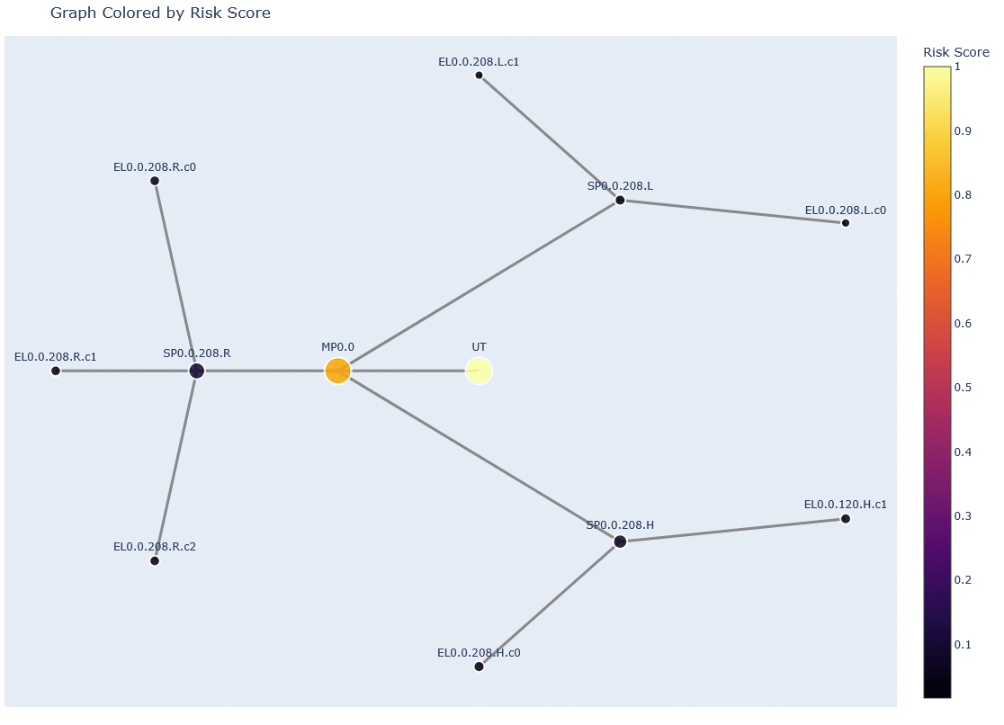
Appendix B: Example Test Data: Complex Building
The following parameters were used to generate a complex building for testing and validation of the AssetPulse simulation tool:
- Construction Year: 2000
- Total Load: 1000 kW
- Building Length: 20 m
- Building Width: 20 m
- Number of Floors: 4
- Floor Height: 3.5 m
- Cluster Strength: 0.95
- Random Seed: 42
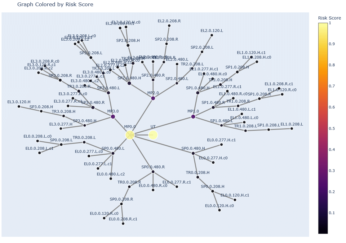
Example Generated Building Graph
Types of Nodes
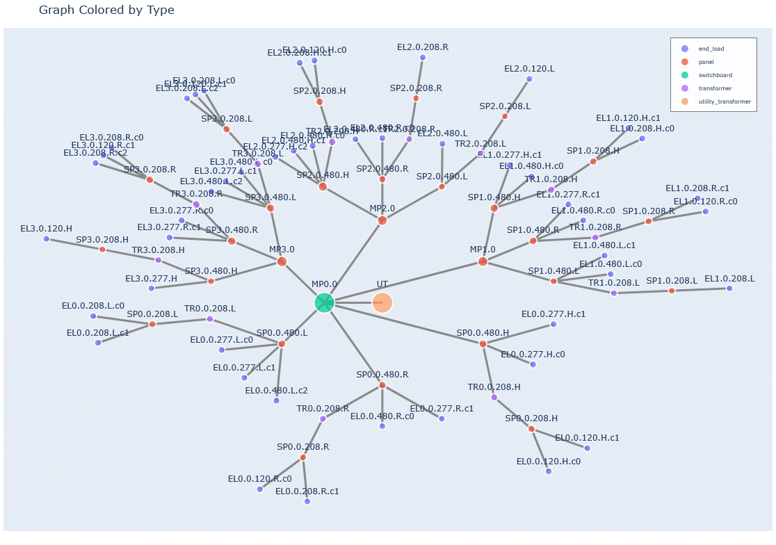
Risk Levels
Appendix C: Screenshots of the AssetPulse Interface
Below are screenshots of the various features and views available in the AssetPulse user interface.
System View
Nodes Colored by Type
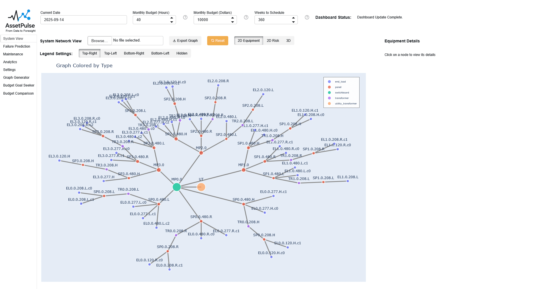
System View Page – 2D Equipment View
Nodes Colored by Risk Score
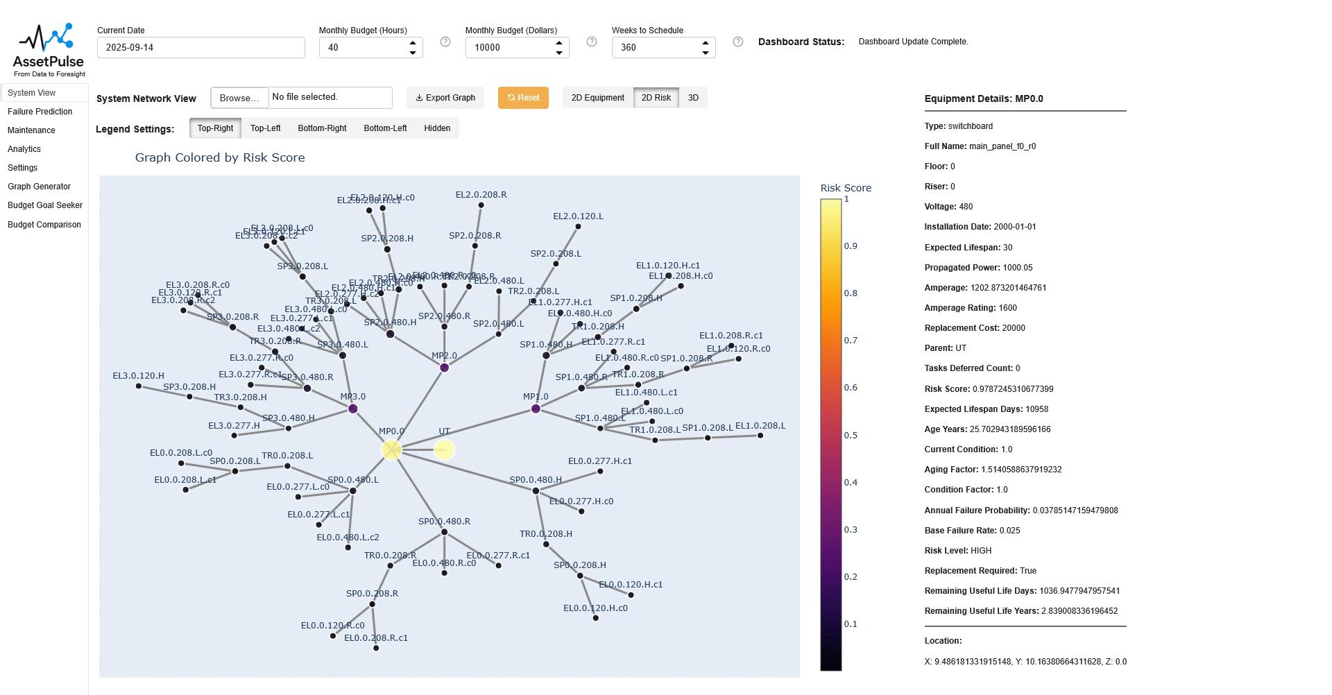
System View Page – 2D Risk View
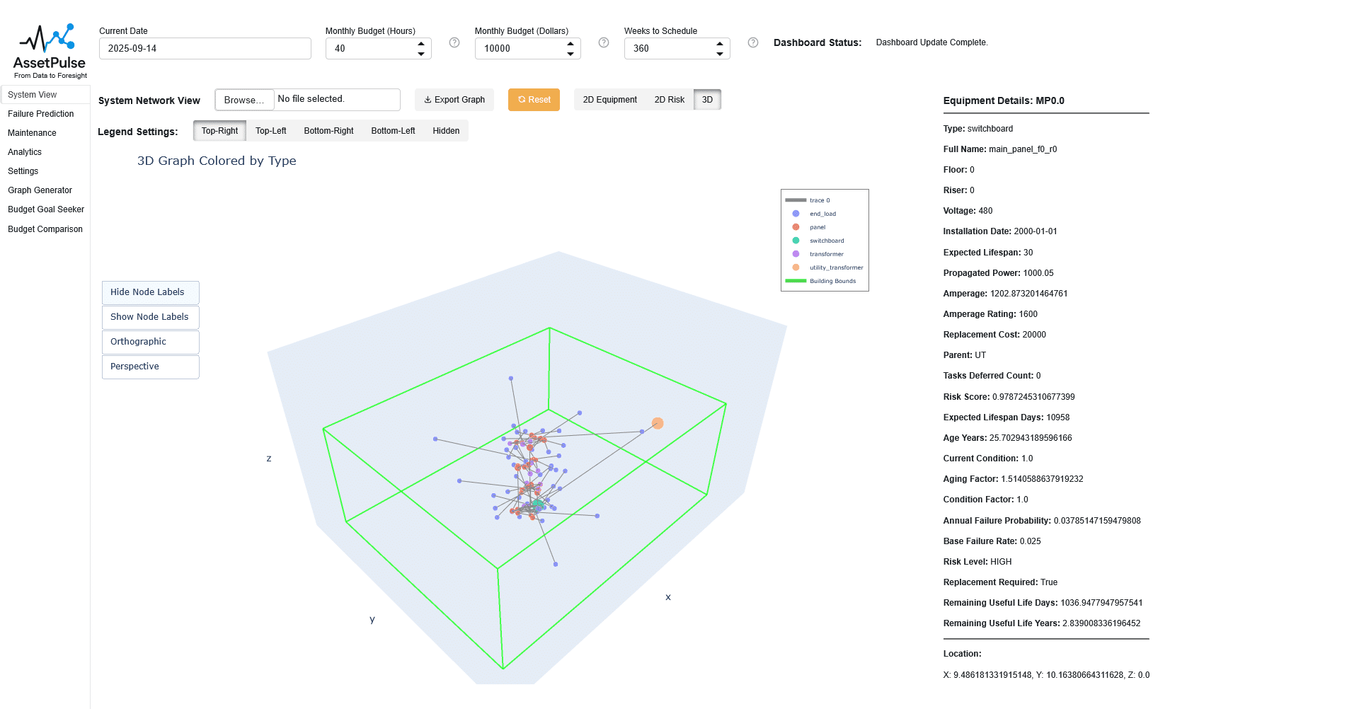
3D View of the System
Failure Prediction
Maintenance
Maintenance Task List
Replacement Task List
Budget Summary
Analytics
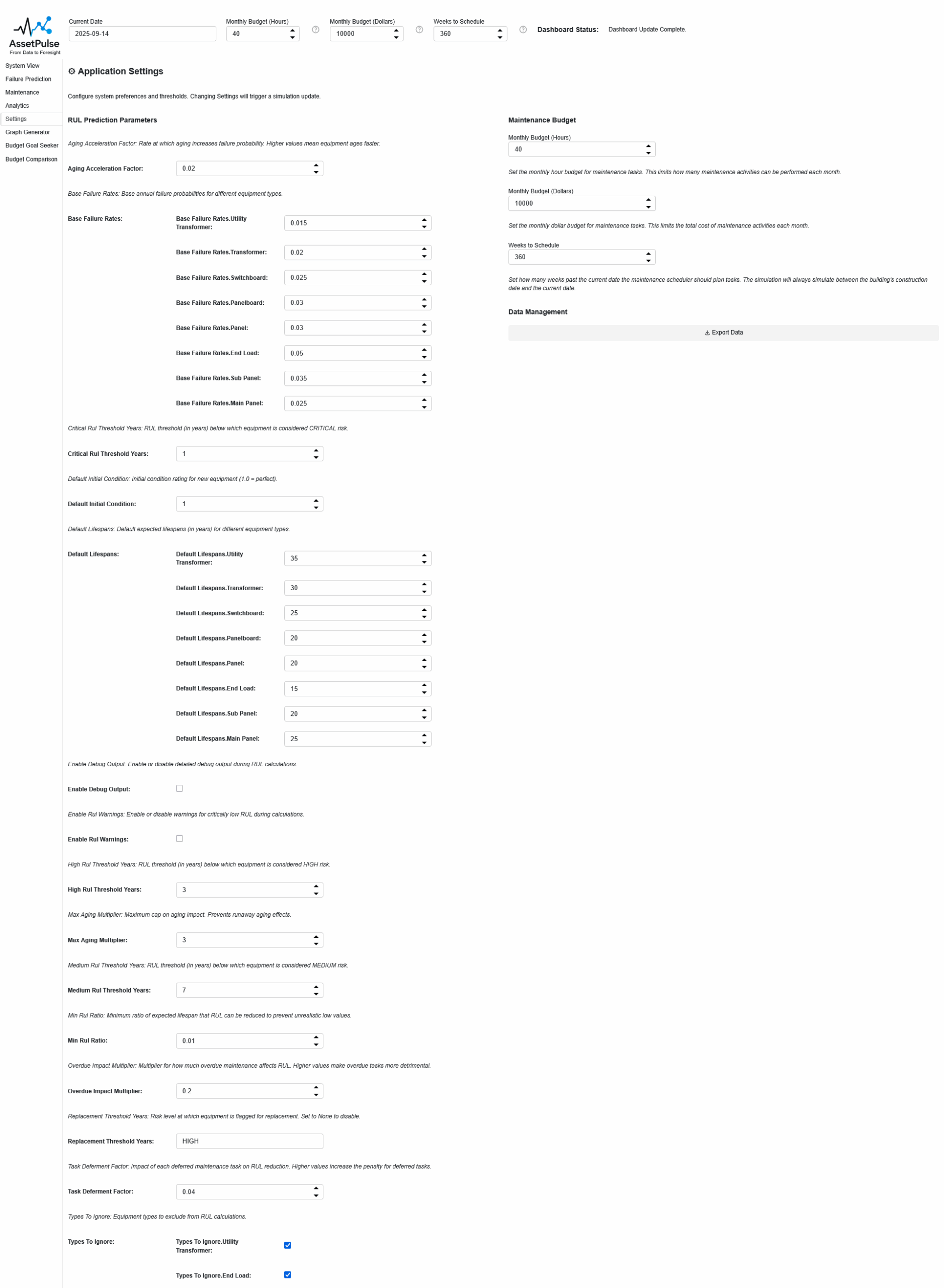
Settings
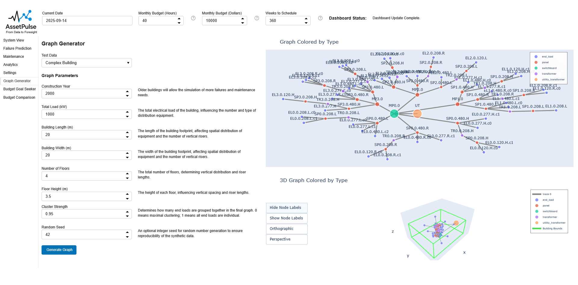
Graph Generator
Budget Goal Seeker
Budget Scenario Comparison