
The Nidra Chair was developed within the framework of Workshop 1.1, where we explored robotic milling using the KUKA robotic arm. The design process was guided by a set of conceptual ideas—texture, nest, wings, and storage—which shaped the formal and tactile language of the piece. Inspired by notions of protection, warmth, and well-being, Nidra seeks to create a space that embraces the body, like a hybrid between a shell, an egg, and a dragon’s nest.After an initial exploration of multiple design alternatives, we selected those geometries that could be feasibly produced using the milling technique. The texture of the chair was then refined to give it a dragon-like skin, enhancing its tactile quality. The fabrication process included the preparation and lamination of wooden sheets to form a solid mass, digital simulation to predict material behavior, and the programming of the robotic toolpath for subtractive manufacturing. Finally, the piece was hand-sanded to achieve a smooth surface.
Form of the Chair
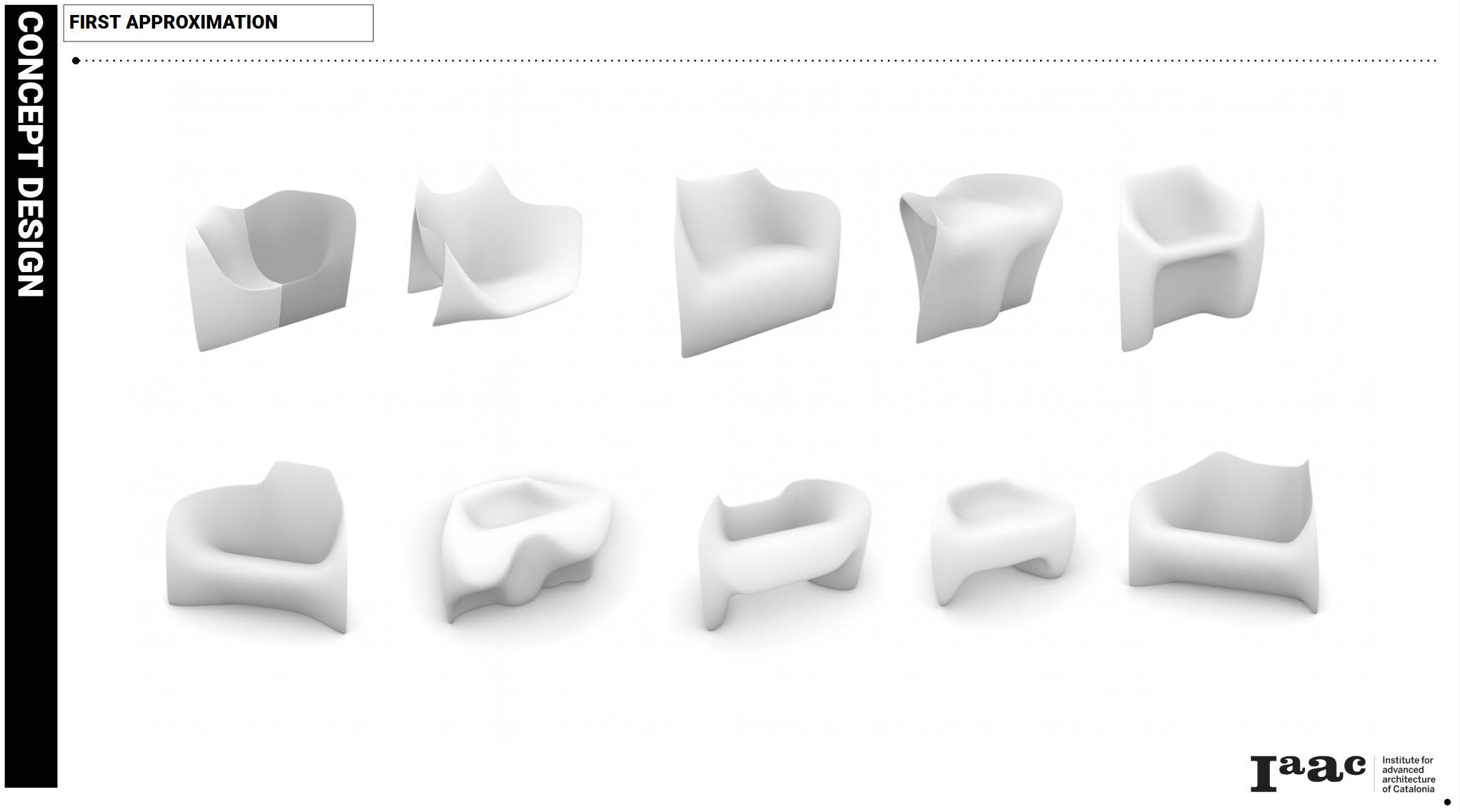
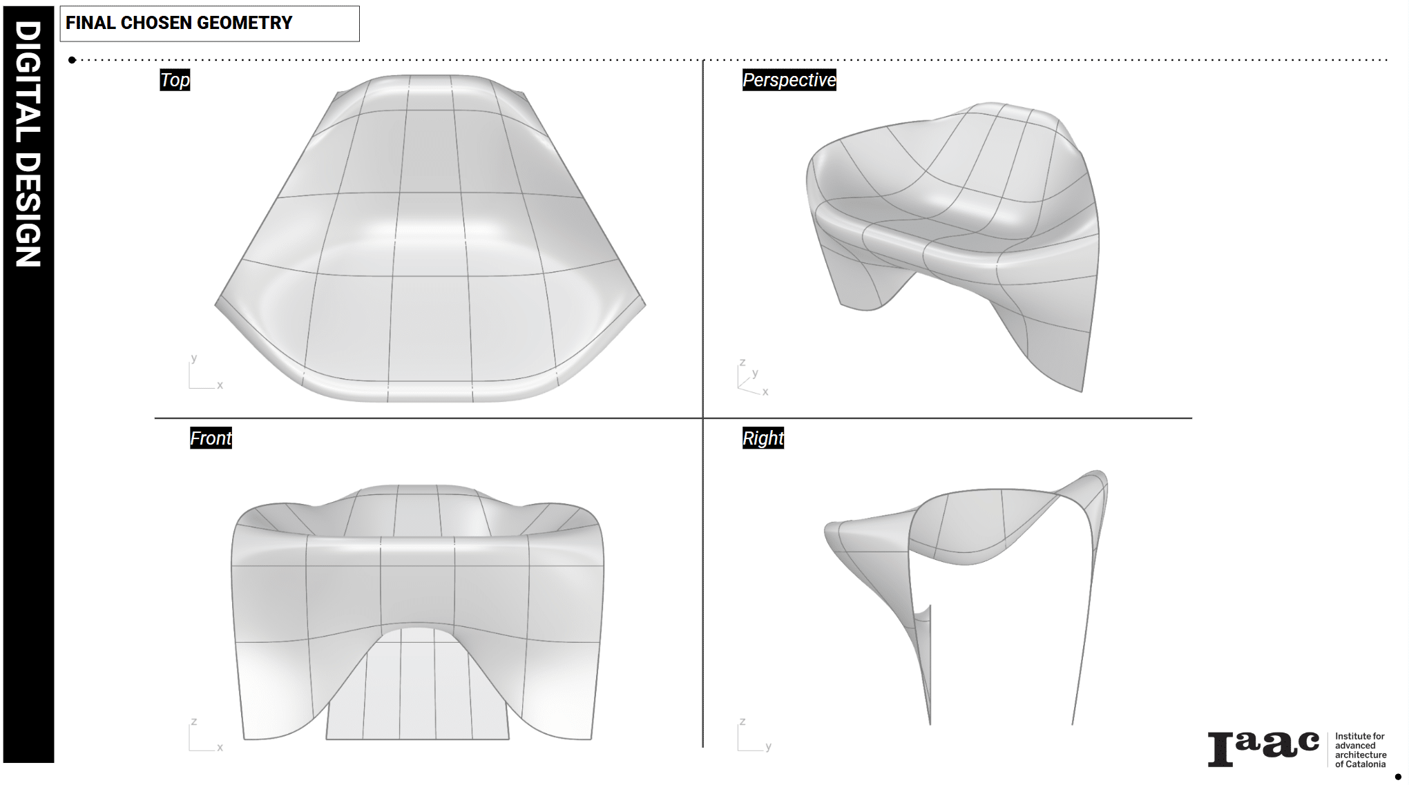
For the initial shape of the chair, we started from an egg-like base, wide enough to comfortably accommodate a seated person. The geometry was modeled using an open SubD approach, which allowed us to treat it as an open surface. This method made it possible to remap the subdivisions and adjust their density, giving us greater control over the distribution of texture across the form.
Texture
To develop the concept of dragon scales, we used the Weavebird plugin in Grasshopper to control the panels of the initial surface. This process generated pointed extrusions on each face of the geometry. The height of these extrusions was varied according to their distance from a set of control points placed on the surface. By doing so, we were able to preserve a central area that remained smooth and comfortable for sitting, while gradually increasing the height of the scales toward the edges. The result was a gradient effect across the surface, combining ergonomic considerations with a strong tactile and visual identity.


Sectioning for fabrication
We generated a sectioning of the chair’s form in order to produce the individual pieces for assembly through CNC milling, using wooden boards with a thickness of 24 mm. Each section was designed with an additional 20 mm margin, which served as extra material to be removed during the roughing process. Once the pieces were cut, they were mounted and joined together.

.gif?raw=true)
Photogrammetry
During the assembly process, dimensional inconsistencies appeared, and the physical model did not fully match the expected dimensions from the digital design. To address this issue, we carried out a photogrammetry scan of the assembled piece. The resulting 3D model was then rescaled and adjusted in the virtual environment, allowing us to use it as a precise reference for the subsequent roughing process. This step ensured that the fabrication could continue with greater accuracy, aligning the physical outcome with the intended design.

Toolpath Generation
With the physical model already digitized, we created the toolpaths by dividing the geometry into specific zones and patches. This allowed us to adapt the inclination of the milling head in each area, optimizing the movements of the robotic arm and reducing unnecessary strain on the machine. The strategy resulted in a total of eight toolpath sections, which structured the milling process into manageable stages and ensured greater precision and efficiency during fabrication
