
A Hybrid Robotic-Human System for Adaptive Woven-Earthen Construction
Abstract
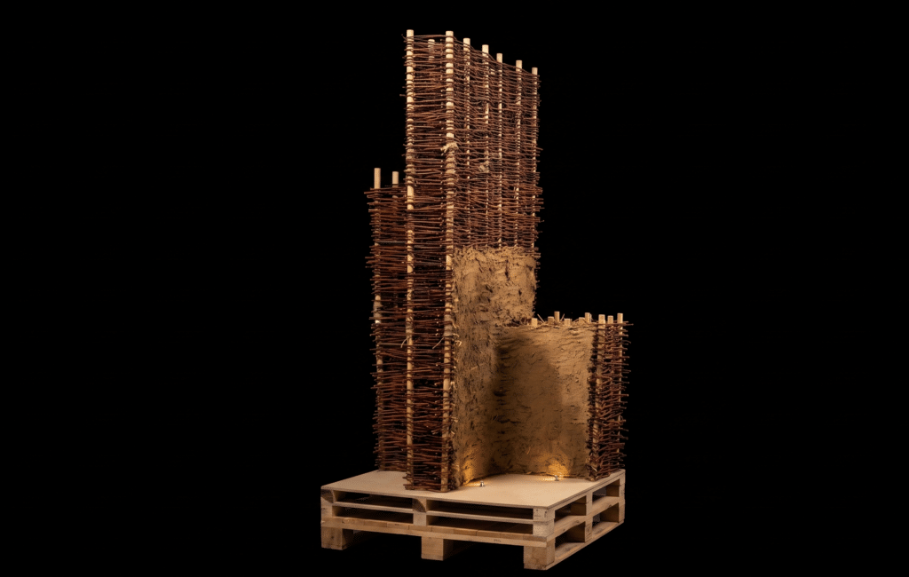
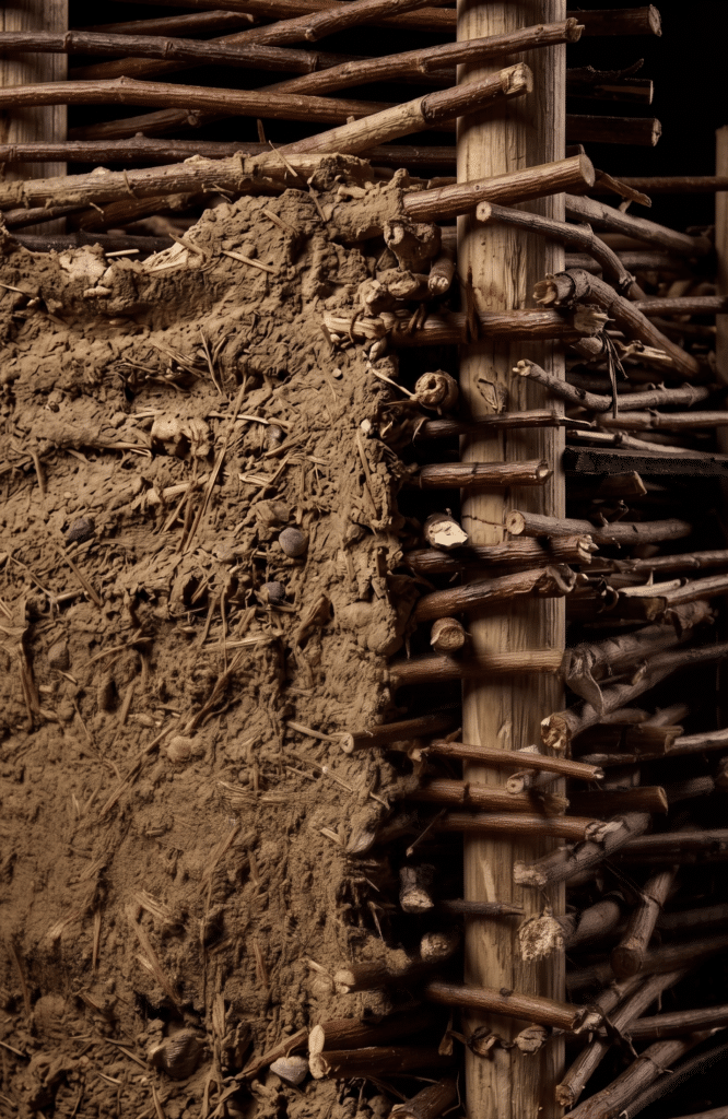
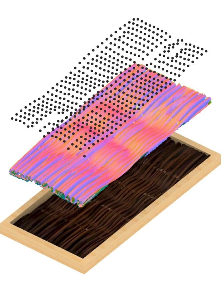
Woven Earth reinterprets traditional willow weaving and earth construction as a digitally informed architectural system. Drawing from vernacular techniques such as wattle and daub, the project develops a hybrid construction method combining woven willow, variable-thickness cavities, and robotic fabrication. Infill strategies layer light earth and straw to achieve zone-specific thermal performance.
A computational finishing system applies earth with controlled nozzle parameters, creating non-uniform tactile surfaces that complete the system. Through material testing, structural analysis, computational workflows, and full-scale prototyping, Woven Earth establishes a scalable, low-carbon building system that integrates local materials with advanced manufacturing, demonstrating how craft knowledge can evolve into circular, adaptive architecture.
INTRODUCTION: THE RETURN TO MATERIAL INTELLIGENCE
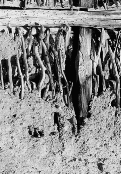
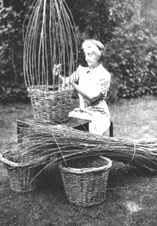
For centuries, wattle and daub buildings sheltered communities across Europe. Simple, effective, entirely local. But beneath that simplicity lay centuries of accumulated knowledge, how willow bends, where it breaks, how to layer it with earth for strength and thermal comfort.
Our project challenges a false binary: tradition or technology. Instead, we asked: what if we could extract the intelligence embedded in vernacular techniques and amplify it through robotic precision while preserving human agency?
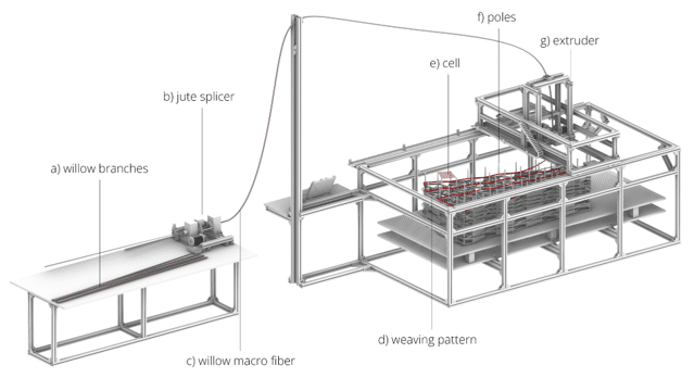
The result is Woven Earth, a three-dimensional hybrid wattle and daub system that combines:
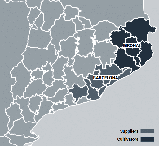
- Willow weaving at variable thickness (0km-local material from Girona, Catalunya).
- Robotic fabrication for precise curve control.
- Multi-functional cavities that serve as structure, which is an oportunnity for thermal mass, and architectural expression.
LEARNING FROM TRADITION: BASKETRY & VERNACULAR INTELLIGENCE
Why Vernacular Techniques Matter
Wattle and daub is not a primitive technology waiting to be “improved.” It’s a system refined across centuries, optimized through thousands of iterations of feedback. In Spain, the zarzo. In England, wattling. In the Mediterranean, ripari structures. Each regional variant solved real problems: how to keep earth infill from spilling out, how to respond to local humidity cycles.
But here’s what’s been lost: the why of each weaving pattern is embedded in craft knowledge, not documented in rules. A master weaver knows that alternate thick-thin fibers distribute stress differently than uniform thickness. A builder knows that border weaves must be tighter than interior fills.
Our project inverted that problem: we extracted the structural intelligence from basketry, wattle-and-daub tradition and zarzo, then codified it as a generative system that could drive robotic fabrication.
The Techniques We Drew From:
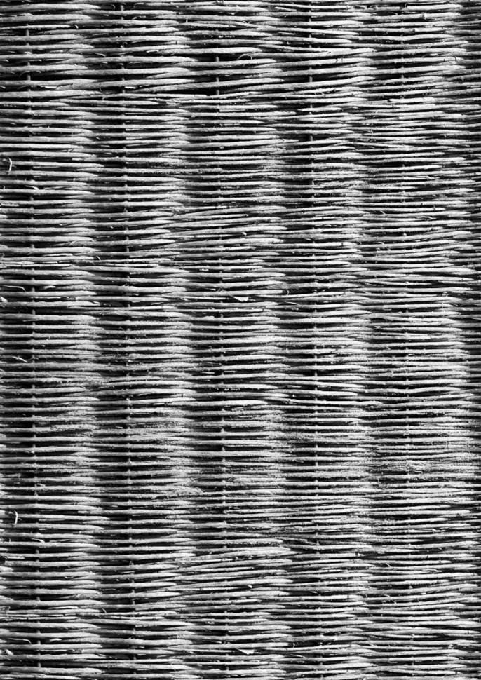
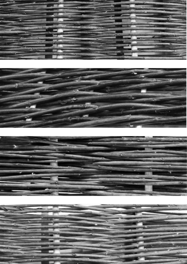
- Linear weaving (zarzo): Simple over-under progression, directional strength, fast.
- Patterned weaving (randing, three-rod wailing, slewing, pairing) — Denser interlock, handles thickness variation, more decorative
- Border vs. interior logic : Borders establish geometry first; interiors create cavities for infill
The key insight: these are not aesthetic choices; they encode structural behavior. The pattern is the load path.
STATE OF THE ART
Scanning the Field
Before developing Woven Earth, we mapped existing research to understand the landscape. Two projects stood out:
ReGrow Willow (KIT). A robotic 3D printer–type machine that weaves willow around vertical guides, then deploys the resulting structure as horizontal spanning panels. Earth infill functions as a structural component.
Robotic Softness (ITECH). Explores behavioral robotic fabrication with gripper-based weaving strategies, emphasizing material responsiveness.
.
Woven Earth (IAAC). A simplified robotic weaving system wich use the state of the art as core that translates hand-weaving motion into robotic logic through biomimetic analysis. Fabricates willow structures around vertical guides in sequential vertical assembly. Earth infill is integrated layer-by-layer. Result: superior curve quality through robotic precision applied to vernacular gesture.
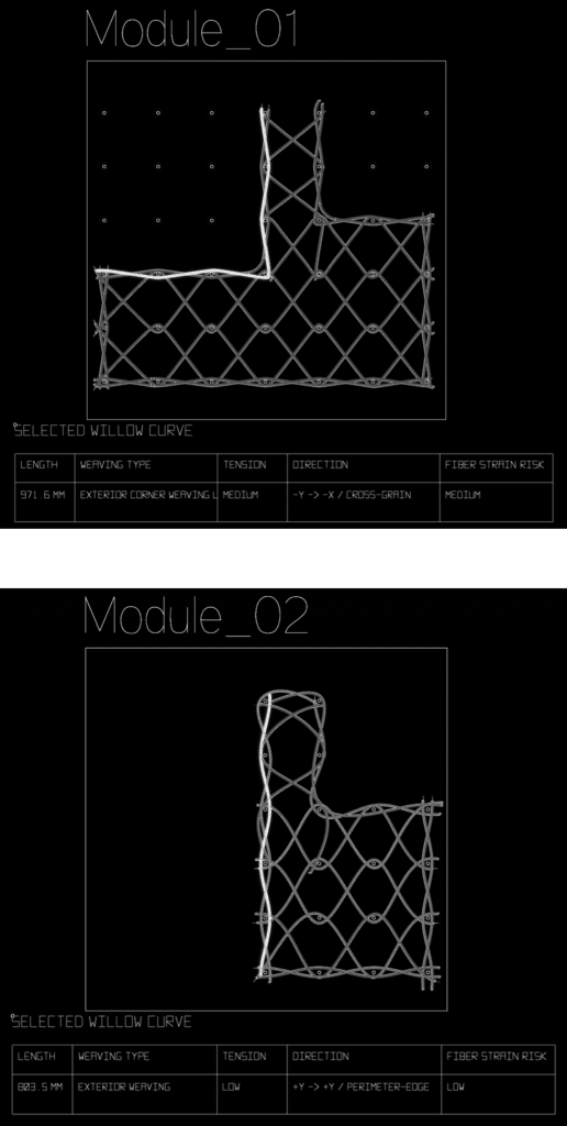
TRANSLATING VERNACULAR TECHNIQUES INTO MOVEMENT
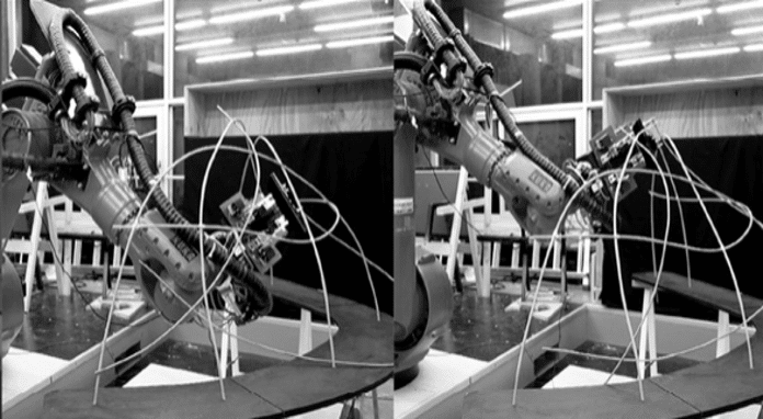
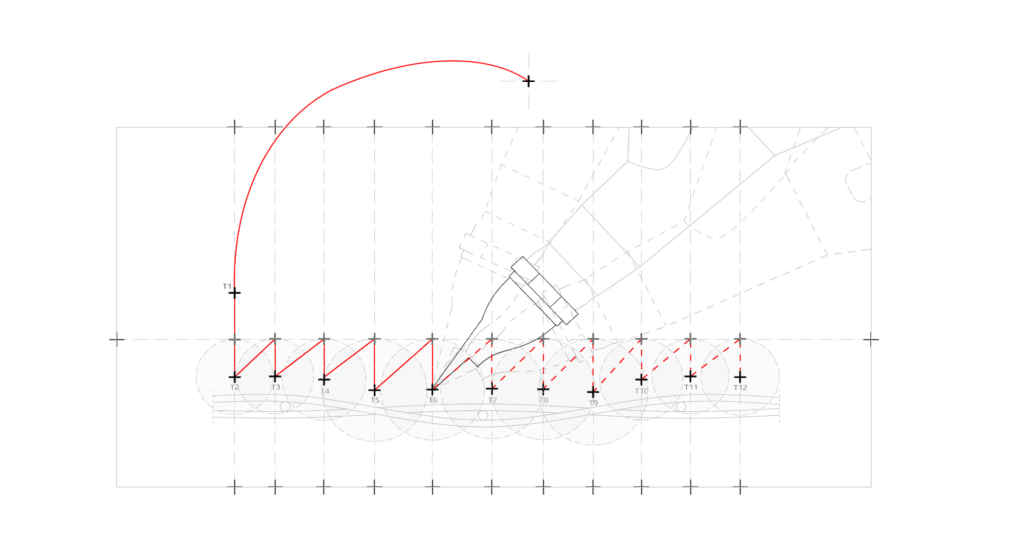
We conducted hand-tracking studies of traditional willow weavings, capturing the precise motion paths of manual weaving. From this data, we abstracted movement patterns into parametric robot trajectories.
The result: the robot executes the logic embedded in centuries of craft knowledge.
This produces a specific advantage: robotic precision applied to vernacular gesture creates superior curve quality. Where hand-woven curves contain irregularities and variations, the robot-executed weave achieves geometric consistency, smoother and accurate curves.
The system is built for vertical, sequential assembly, layer upon layer, each layer woven, infilled, and stabilized before the next layer begins.
WHY WILLOW? LOCAL CONTEXT & MATERIAL INTELLIGENCE
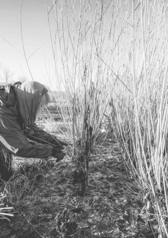
The Case for 0KM Material
Girona, 60km northeast of Barcelona, has a 300-year history of willow cultivation. Harvesters know the seasonal timing, the thickness that works, the bending radius of each species.
Why This Material?
- 0KM sourcing: Willow is cultivated in Girona. No international shipping. Minimal carbon overhead. Harvesters can be engaged directly.
- Structural flexibility: Unlike timber, willow can be bent cold into complex geometries. It doesn’t crack under sharp bends the way hardwood does. It can be woven into tessellating patterns without mechanical joinery.
- Growth cycles: Willows coppice (regrow) annually after harvest. Regenerative at a human timescale. Not a centuries-old tree; annual renewability.
- Tactile knowledge embedded : Weaving engages your hands directly with material behavior: how much a rod bends, where it cracks, how it flexes under load. Robotic fabrication layers precision on top of that embodied knowledge, not replacing it.
MATERIAL BEHAVIOR: FROM INTUITION TO DATA
Mapping Cracking, Bending, Deformation
Willow is alive, it moves with humidity, splits when bent past its radius, deforms under load. Traditional builders handled this through rule-of-thumb: “never bend tighter than this,” “always use rods this thickness.”
Our project digitized that intuition.
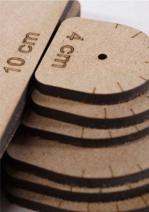
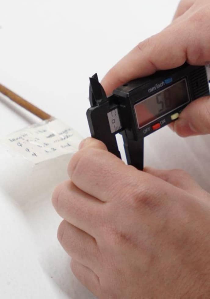
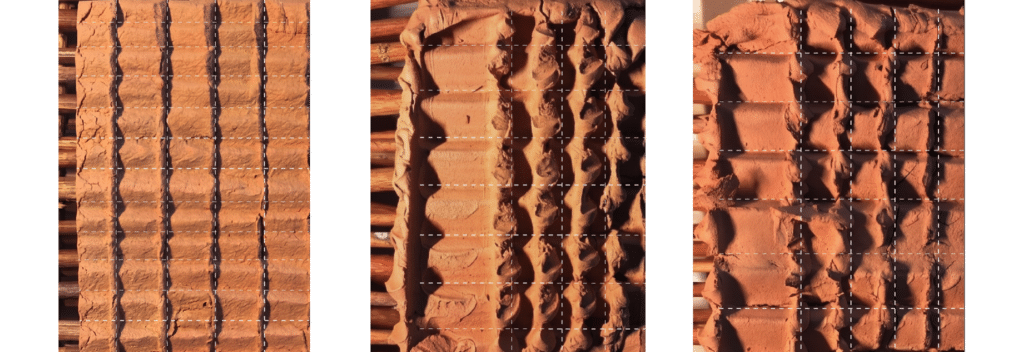
Graduated curvature testing disk. Each concentric ring represents a different bending radius. By wrapping dried willow around the disk, we identified the critical radius at which the fiber begins to crack, establishing the minimum safe bending envelope for the robotic system.
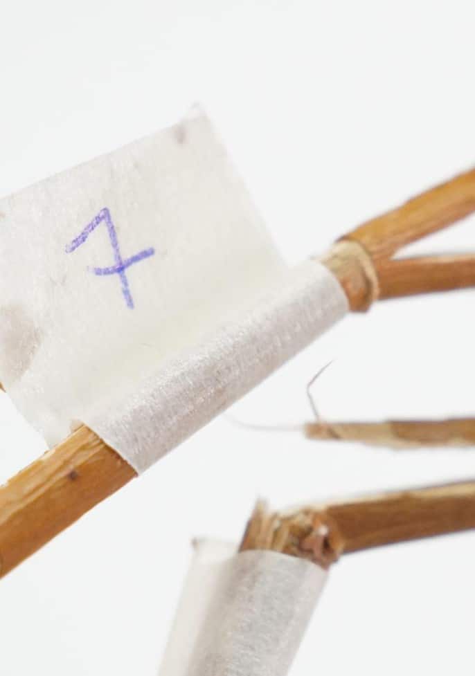
Fiber failure documentation. Each broken sample is tagged with its critical diameter (in cm) at fracture point. This data feeds the curvature matrix, establishing the relationship between willow thickness and maximum bendability.
Material inventory and characterization. Each willow fiber is measured and tagged with its length and diameter. Combined with bending test results and failure-point data, this creates a database linking fiber geometry to structural performance, essential for parametric weaving design.
Three Material Behaviors We Studied:
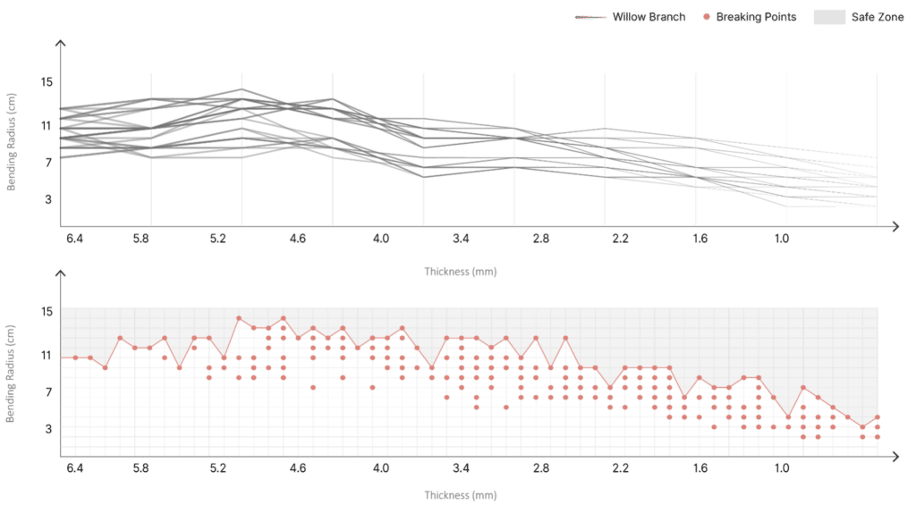
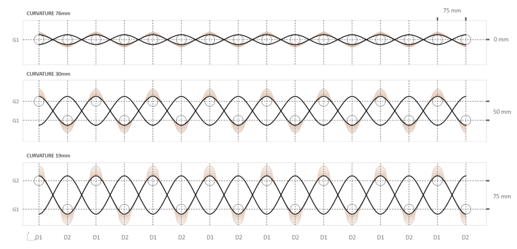
- Bending radius vs. thickness. At what diameter can a willow rod bend 45°, 90°, or tighter before cracking initiates?
- Deformation under load. How does a filled cell behave when supporting weight? Where is the failure point?
- Drying and cracking patterns. After earth infill hardens, how do wood and earth move differently? Where does stress concentrate?
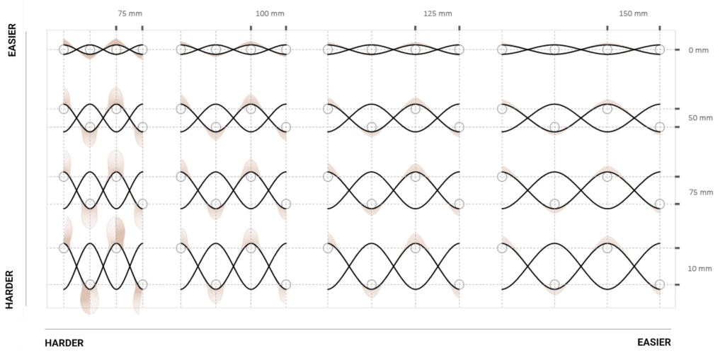
We built curvature matrices; physical and digital tests at scales from 5cm to full-scale maquettes; to create lookup tables for the robotic fabrication system.
WEAVING LOGIC: FROM2D PATTERN TO 3D GEOMETRY
The Four Rules of Woven Earth
Once we understood material behavior and extracted intelligence from vernacular weaving, we distilled the system into four operational rules. These aren’t arbitrary, each one solves a specific structural or construction problem:
Rule 1: Fiber Balance (Taper Rule)
Alternate thick and thin willow fibers along each line of the weave. In one pass: thin fiber. In the return: thick fiber. This distributes stiffness and stress across the entire weave rather than concentrating it at weak points.
Why? Uniform-thickness weaves develop stress concentrations where fibers accidentally align in ways that form weak paths. Variable thickness breaks those paths.
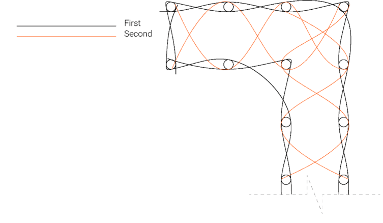
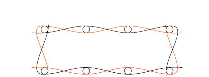
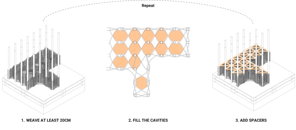
Rule 2: Border-First, Interior-Second Weaving Sequence
Weave the outer edges first, tightly, to establish the perimeter geometry. Only after the border is locked down do you weave the interior passes, these interior passes form the cavities that will later be filled with straw or light earth.
Rule 3: Counter-Locking Pass for Planar Finish
After the border and interior are complete, add a final crossing pass, one that goes perpendicular to the main weave direction, to lock all cells in place and stiffen the entire structure. This pass also closes any gaps and creates a more uniform surface for earth finish.
Why? Without it, adjacent cells can shear against each other, especially under load or when earth is rammed in. The counter-lock increases overall stability with minimal extra material.
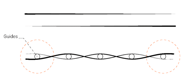
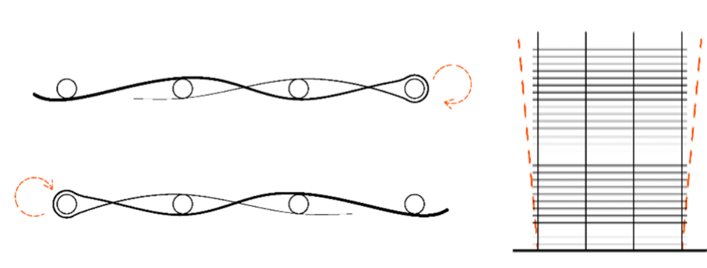
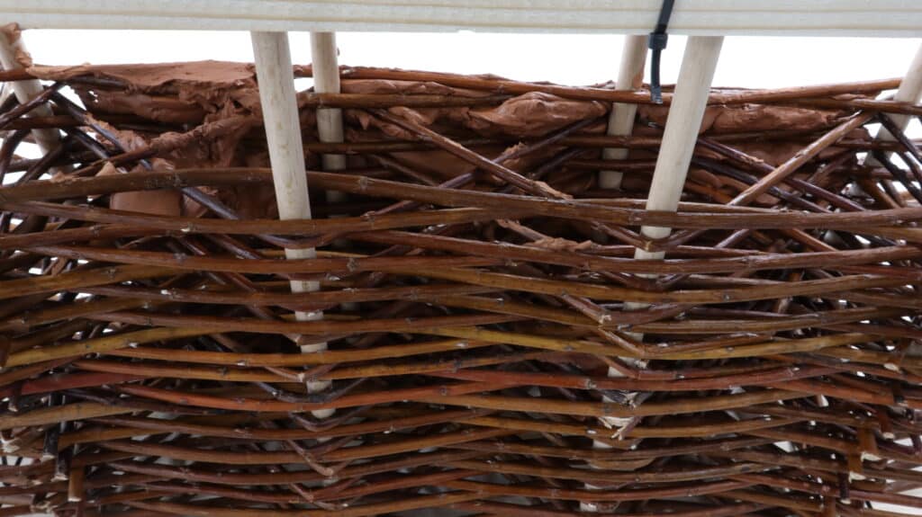
Rule 4: Guide-Return Loop
The outermost willow fibers make a 180° turn around the structural guides (vertical posts/columns) that anchor the wall. This loop prevents the naturally spring-like willow from deforming outward.
Why? Willow wants to straighten. Without the return loop, the woven cage gradually springs outward under its own internal stress. The loop channels that energy safely into the guides.
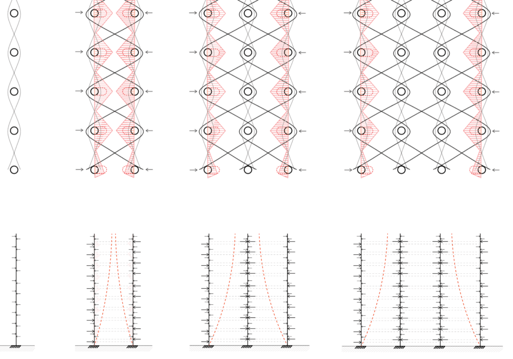
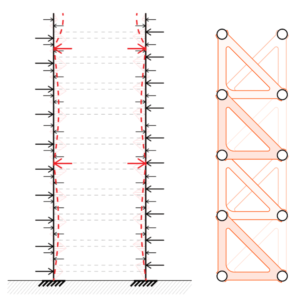
STRUCTURE: DESIGN WITH DEFORMATION
From Hollow Cage to Load-Bearing System
Early prototypes showed an unexpected problem: the woven structure could deform significantly under modest loads. This wasn’t failure — it was behavioral.
We reframed the problem: what if deformation is acceptable as long as cavities remain stable and cracking is controlled?
The solution was structural spacers, thin internal bracing that:
- Prevents cell-to-cell shearing
- Limits deformation to predictable ranges
THE PIPELINE: SEQUENTIAL FABRICATION
How Robotic + Human Work Together
The fabrication sequence is designed for actual construction reality — not a sterile lab, but a building site.
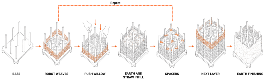
The Cycle:
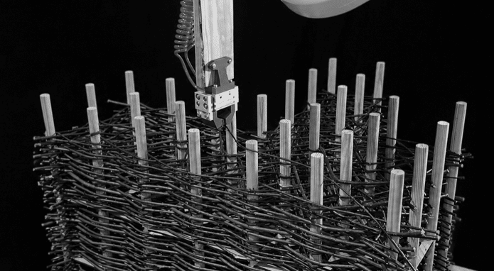
- Prepare base: Structural frame with guides (round wooden posts).
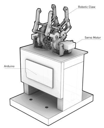
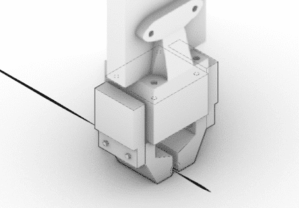
- Robot weaves: ABB IRB 140 follows the optimized weaving pattern, incrementally around the guide.
- Push willow: Human worker compacts woven layer against guides (critical tactile feedback moment).
- Infill cavities: Light earth and straw rammed into the selected cells.
- Add spacers: Thin timber bracing inserted into predetermined slots (add after 20cm weaving).
- Next layer: Repeat upward or outward
- Finish earth: Final earth rendering.
The genius is in the overlap zones. Each layer doesn’t wait for the previous to fully cure — assembly continues while infill dries, telescoping total build time from months to weeks.
THERMAL PERFORMANCE: CAVITIES AS DESIGN INTELLIGENCE
The Thickness Becomes a Feature
Traditional wattle and daub is thermally competent, not because of theory, but because of thickness and thermal mass. A wall 30cm thick with earth has significant lag
Our variable-thickness approach lets us optimize locally:
- High-performance spaces, Straw-filled cores for maximum insulation
- Comfort-focused spaces, Light earth (straw + clay binder) for thermal mass and humidity regulation
Material Strategy: Straw vs. Light Earth
The system uses two primary infill strategies:
Straw-filled cores (λ = 0.06 W/m·K):
- Pure straw: maximum thermal insulation
- Best for low U-value performance (classrooms, offices, exterior facades)
- Results: U-values 0.27–0.39 W/m²K at 30–45cm thickness with 50% cavity fill
- Trade-off: Requires careful protection from moisture (good detailing essential)
Light Earth-filled cores (λ = 0.10 W/m·K):
- Paja wrapped with arcilla as adhesive binder (~70% paja, 30% arcilla)
- Superior thermal mass and hygroscopic comfort (regulates interior humidity 40-60%)
- Best for spaces requiring temperature/humidity regulation (leisure areas)
- Results: U-values 0.58 W/m²K at 30cm thickness with 50% cavity fill, plus excellent acoustic performance (STC 48 dB)
- Added benefit: Protective arcilla coating prevents paja degradation
Why 50% Infill?
The cavity isn’t completely packed. Variable infill allows:
- Lighter construction (50% mass vs. fully-filled)
- Acoustic absorption zones (intentional void pockets)
- Faster assembly and easier future modifications
- Cost optimization without sacrificing performance
Performance Across Programs:
Each zone is tuned for specific function. Rather than a monolithic approach, we compose weave density + infill material + cavity thickness to achieve local optimization: ProgramWall TypeU-valueThicknessFill MassStrategyClassroomC35-Straw-F30.27 W/m²K51 cm123 kg/m²Thermal mass for equipment + occupancy bufferingStudy AreaC30-Straw-F20.39 W/m²K34 cm82 kg/m²Moderate insulation, lighter profileLeisure/ChillC30-Light Earth-F30.58 W/m²K36 cm172 kg/m²Thermal mass + hygroscopic comfortCirculationC15-Air-F22.52 W/m²K19 cm64 kg/m²Structural skeleton; semi-conditioned
This becomes a design tool, not an afterthought. The architect specifies thermal performance; the system delivers it through cavity variation, not through adding external insulation layers.
FEEDBACK AND VALIDATION — DIGITAL ↔ PHYSICAL
Closing the Loop
A major project risk was hypothesis mismatch — will the thing actually behave like the models predict?
Our validation cycle was ruthlessly practical:
Digital Prototype (Grasshopper/Rhino):
- Parametric weaving logic
- Structural analysis (FEA)
- Robotic path generation
- Thermal simulation
Physical Prototype (1:1 at 2m height):
- Build the thing
- Measure actual deformation
- Sample straw infill
- 3D scan the completed structure (photogrammetry → point cloud)
Feedback Loop: Point Cloud as Design Input
The 3D scans of the physical prototype (recorded as point clouds in Metashape) become critical data:
- Geometric validation: Compare point cloud to digital model. Identify drift, settling, or unexpected deformation. Measure actual vs. predicted cavity depth and wall thickness.
- Finishing system input: The point cloud data feeds directly into the robotic earth finishing system. Rather than applying finish to a theoretical surface, the robot receives real geometry. Custom toolpath generation accounts for actual surface irregularities, guides, and structural features present in the built prototype.
- Adaptive application: Finishing earth nozzle parameters (height, angle, pressure) adjust across the surface based on point cloud geometry. Where the weave deviates from model, finish application compensates. Where cavities have settled, finish fills adaptive cavity thickness. The finishing system responds to reality, not assumption.
FINISHING: ROBOTICS FOR SURFACE EXPRESSION
From Structural Skeleton to Architectural Skin
Willow and earth infill create texture, but the surface finish defines how the wall reads in space. We developed a robotic finishing system for earth rendering that:
- Extracts mesh from the woven geometry
- Generates toolpath specific to the wall’s variable profile
- Deposits earth with controlled nozzle width and inclination
- Creates pattern through UV-parameter variation and tool angle
The Finishing Catalogue defined:
- Nozzle width vs. U-count ratio: Creates irregular, non-proportional patterns. This breaks the “CNC grid” aesthetic.
- Tool inclination angle: Modifies material deposition, creating 3D textures with varying heights
- UV variation: Base surface pattern definition
The result: robotic precision in service of tactile, non-uniform expression.
UV COUNT VARIATION
Varying the U and V parameters defines the base surface pattern.
NOZZLE AND U-COUNT RATIO
A non-proportional ratio between the nozzle width and the U count generates distinct, irregular patterns
TOOL INCLINATION ANGLE
The inclination angle of the tool modifies material deposition, creating 3D textures with varying heights.
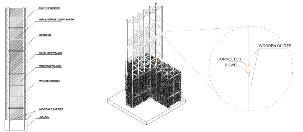
CONSTRUCTION DETAILS: HOW TO BUILD
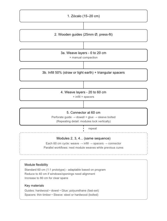
Modular Assembly
The wall builds vertically in independent 60 cm modules, each locked to the one below through a circular sleeve connector. This allows one team to weave while another compacts infill, and finishing to begin on lower modules while upper modules are still under construction.
The diagram shows the complete sequence: from zócalo preparation through guide installation, to the repeating cycle of weaving-infill-spacers-connector. Module height (60 cm, 40 cm for openings, 80 cm for clear spans) is defined early in design and held consistently for fabrication and connector logic.
[IMAGE DIAGRAM | Construction sequence flowchart showing 8 steps: zócalo → guides → weave layers 1–3 + compaction → infill + triangular spacers → weave layers 4–6 + infill/spacers → connector installation → repeat]
Key materials: hardwood guides (oak, chestnut, 25 mm minimum Ø), hardwood tarugo with polyurethane fast-set glue, steel or hardwood circular sleeves bolted at module junctions. Typical pace: 9 m² in 2–3 weeks, 32 m² (IAAC extension) in 6–8 weeks with overlapping module cycles.
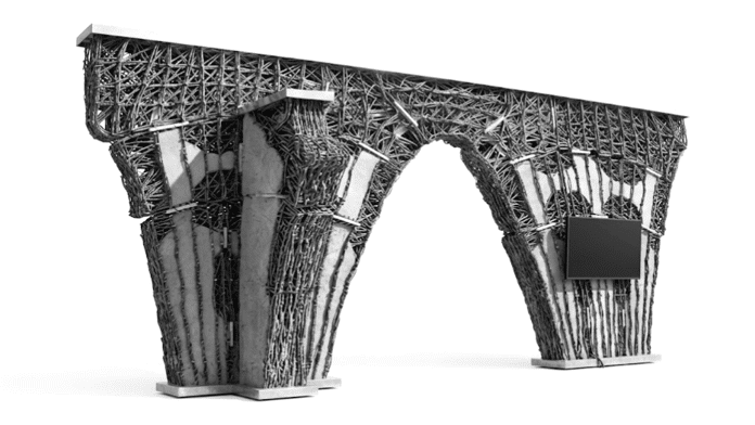
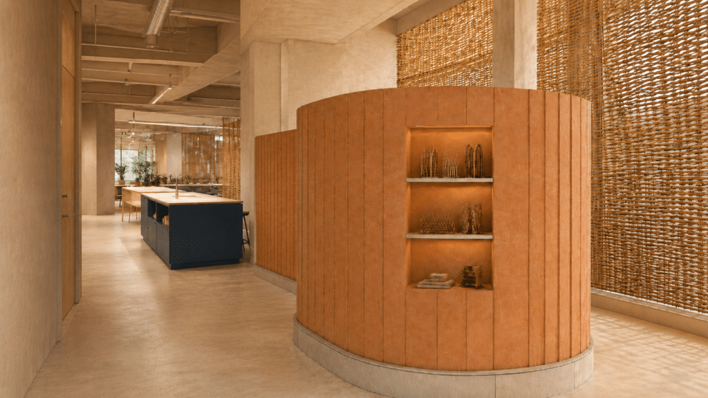
As a result, we have created a 3 dimensional Woven Earth, with different thickness, which can be infilled with different materials based on its spatial necessities.
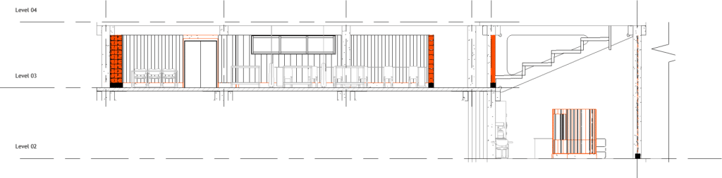
ARCHITECTURAL APPLICATION: WOVEN EARTH AT IAAC
Woven Earth will be part of the design of the in the new IAAC Building, located in Poblenou. Our project ocupate the second and third floor.
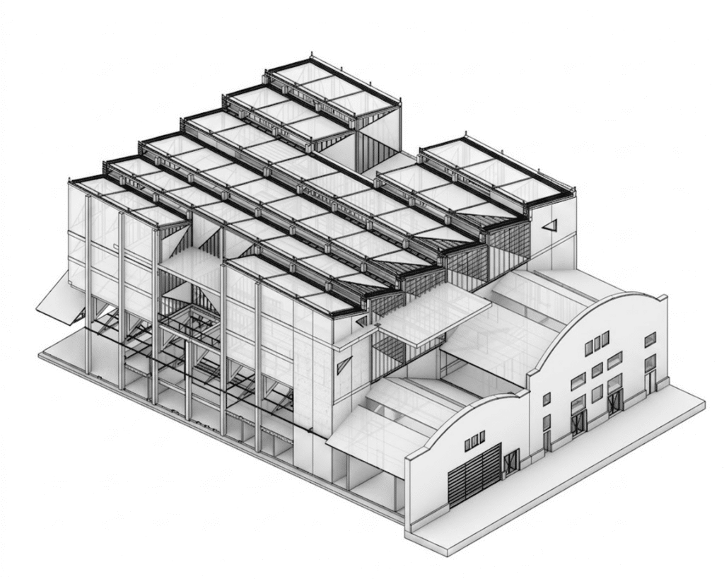
Thickness Responds to Program
The wall doesn’t have one thickness, it has five in Level 3 alone. Same system, radically different responses: thick where thermal mass matters (facade, study separators), thin where visual connection or openness is needed (kitchenette, storage, corridor).
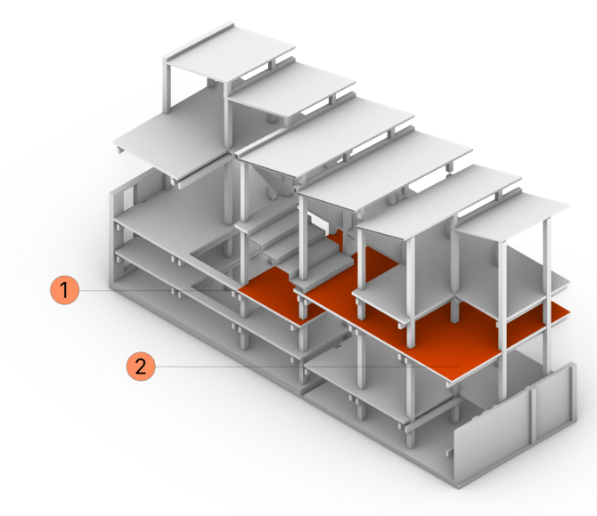
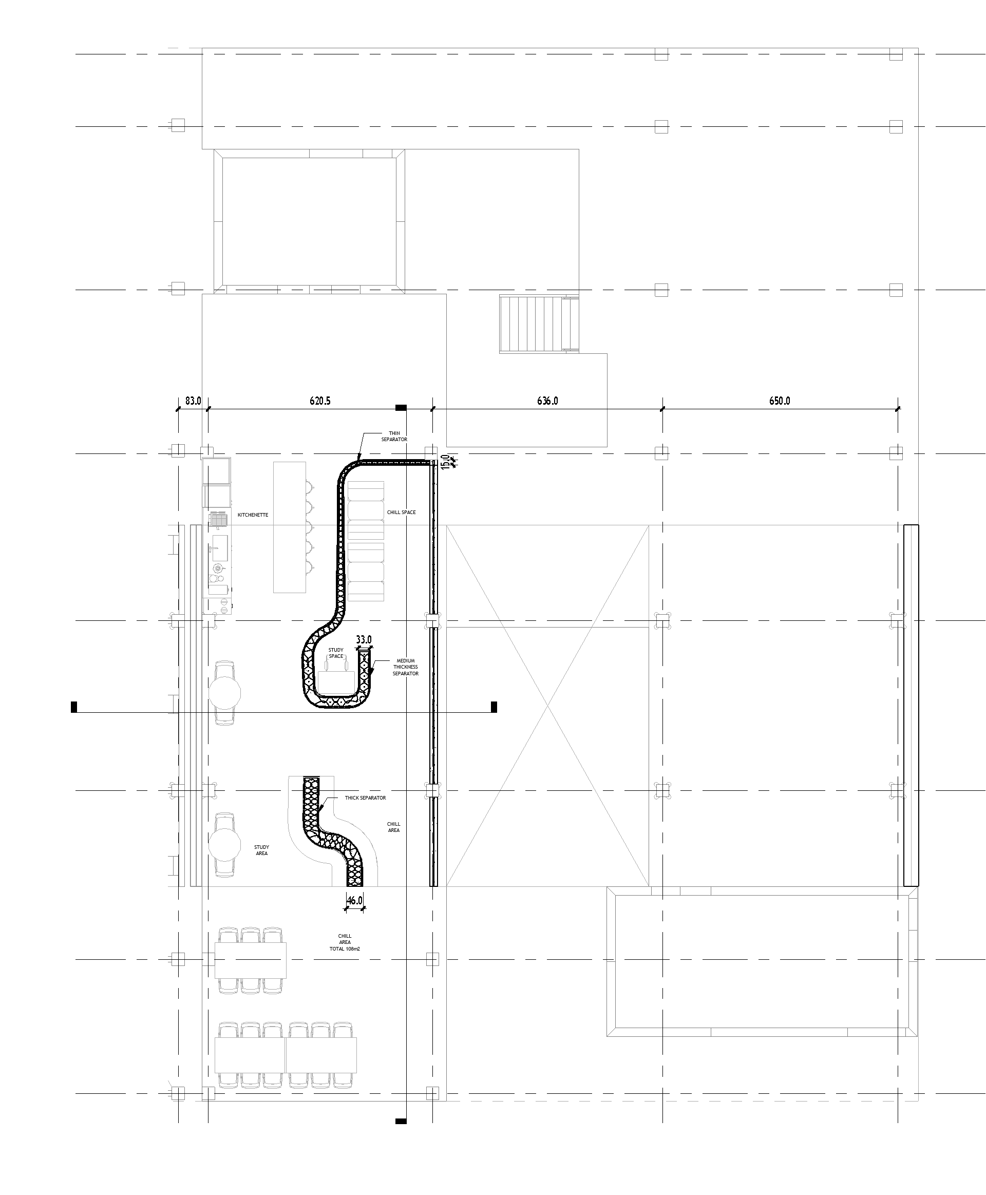
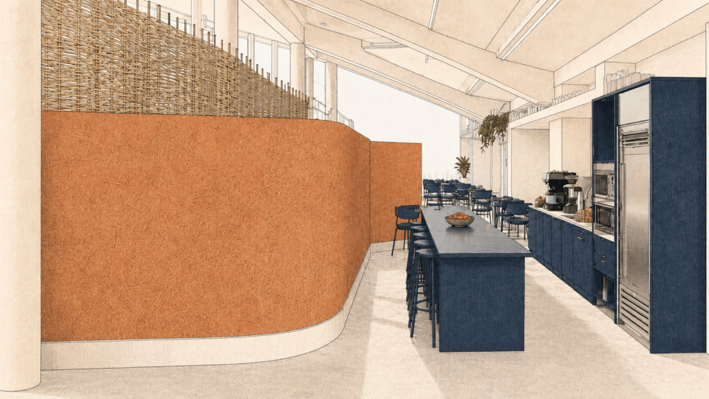
Level 2: Chill Area
The same floor shows dramatic thickness variation:
Thin kitchenette wall (15 cm) with earth finish, lightweight but finished. Minimal presence, allowing visual connection and flow to the chill area.
Thick separators (46 cm) isolate study zones for concentration, straw-infill cores providing thermal mass and acoustic isolation between focused work areas.
Medium study zones (33 cm) support individual desk work with lighter acoustic presence.
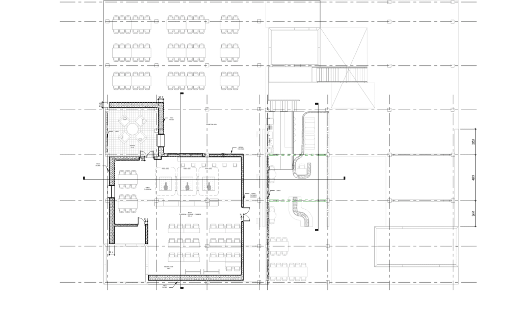
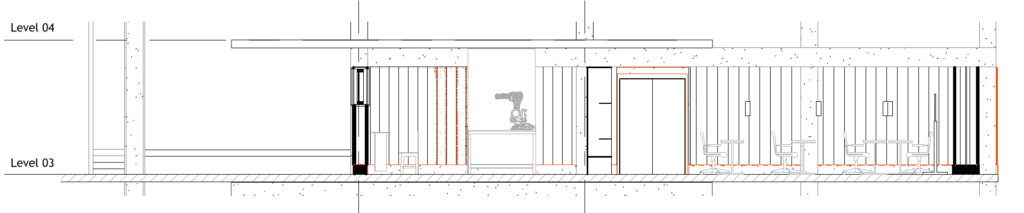
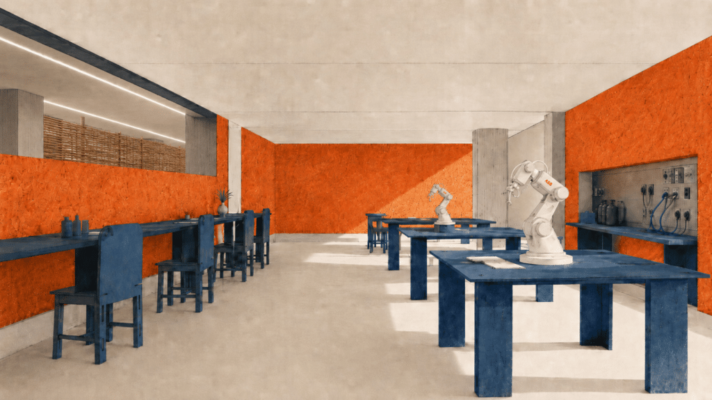
Level 3: Robot Classroom: Five Thicknesses on Display
This is when Woven Earth made visible. One room with four walls responding to four completely different adjacent programs:
- Facade wall: 55 cm Maximum thermal mass to buffer equipment heat, occupancy swings, solar gain. Straw-infilled core.
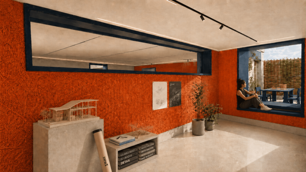
- Terrace wall: 37 cm Medium thickness for outdoor-indoor transition. Light earth infill for humidity and thermal comfort.
- Exhibition wall: 25 cm Thin wall with earth finish, for visual connection to study/display space.
- Storage + corridor wall: 22 cm with earth finish Skeleton proportions but finished. Minimal presence, acoustic separation from equipment noise, visual lightness for circulation.
Plus the surrounding building’s terrace facade/exhibition wall (50 cm) with earth finish (the thick protective skin) and the zarzo beyond (open weave, no earth finish, pure willow structure as visual filter).
Students and visitors see one system speaking five different languages through thickness alone. All interior walls are finished with earth. Only the zarzo is left open for visual filtration and light control.
NEXT STEPS: FOUR RESEARCH DIRECTIONS
1. Apertures Integrated in Weaving Logic
How to weave windows and doors as part of the structure, not cut through afterward? Opening geometry becomes part of the parametric weaving sequence. Fibers curve around aperture frames, density increases above (no lintels), reveals integrate shelving or seating.
Next phase: develop weaving protocols for different aperture sizes and typologies.
2. Parallel Robot Workflow – Weaving + Infill + Finishing
Two robots operating in sequence on the same wall. Robot 1 weaves the structure. Robot 2 follows behind: compacts infill and applies earth finishing in one pass. Optimizes time, reduces manual labor, allows continuous workflow.
Next phase: prototype dual-robot coordination on IAAC extension, measure productivity gains.
3. Technical Walls – MEP Inside Cavities
Integrate mechanical, electrical, and plumbing (pipes, conduits, ductwork) directly into wall cavities instead of surfacing them. The weave structure becomes infrastructure carrier. Requires coordination between weaving logic and MEP routing.
Next phase: develop cavity-sizing algorithms that accommodate both structural spacing and MEP sizing.
4. Prefabrication + On-Site Assembly — Both Valid Paths
Factory-woven modules (2m × 3m, truck-transportable) work equally well as on-site assembly (2-3 week intensive build). Not either/or – both are viable depending on project context.
Next phase: test both strategies on IAAC extension, measure time, cost, waste, structural performance. Data will show which fits which scenario.
