Design Approach
Folded Structure System
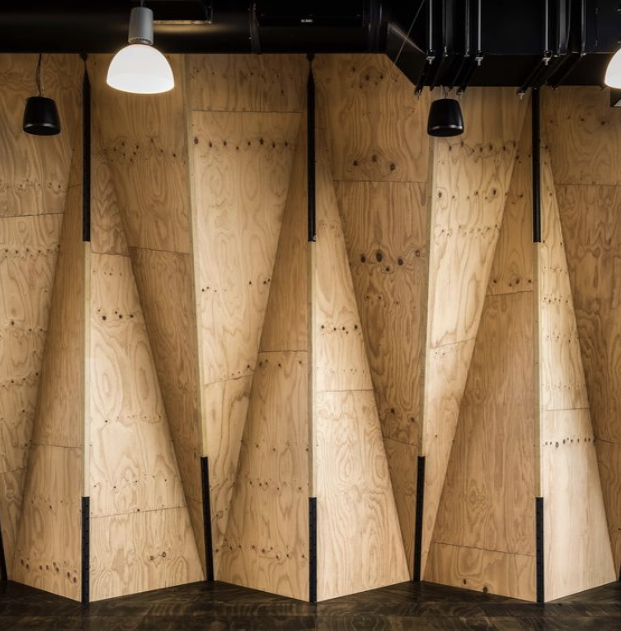
Folded plate surfaces, architectural marvels with interconnected planar elements, gain further dynamism through linear additions. These straight elements seamlessly integrate with the folded structure, enhancing both aesthetics and structural efficiency. The result is a visually striking and functionally optimized design, showcasing the harmonious blend of form and function in contemporary architecture.
Linear Additions
Continuous
LINEAR FOLDING TRUSS
Inspiration
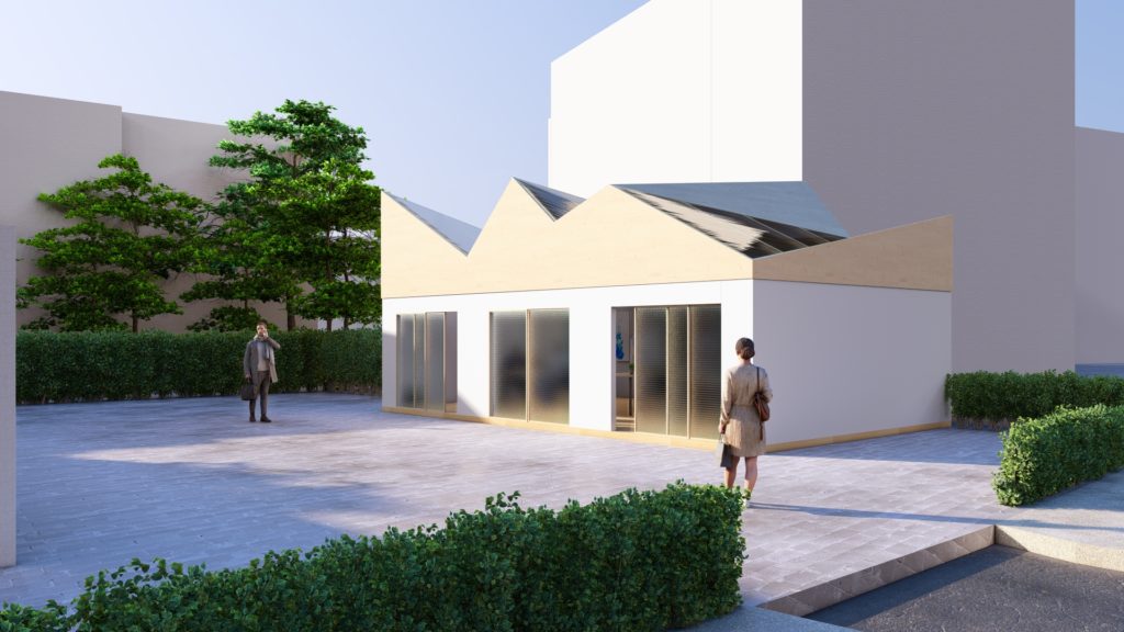
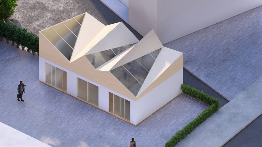
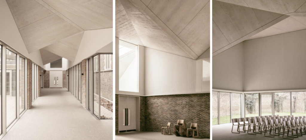
The International Presbyterian Church (IPC) commissioned Piercy& Company to design a new worship and administrative space at the site. The soaring ceilings and vaulted spaces of traditional church architecture offer a key reference point for the church’s form. The pleated roof form creates a finer grain, reducing the perception of the building’s massing within a predominantly residential street. As the roof rises towards the front of the site, the folds peak in an abstracted spire, signaling the building’s ecclesiastical function.
TYPE: Cultural
GROSS FLOOR AREA: 8800 sq ft
STAGE: Completed November 2018
https://www.floornature.com/piercy-company-drayton-green-church-london-15720/
The aim was to create an imaginative, symbolic architectural form, but with a contemporary feel. For example, the pleated roof references the sloping roofs in the road and is characteristic of the local surroundings. It was made possible by using a hybrid steel and laminated timber structure, quickly assembled on site, with minimal waste since components were prefabricated.
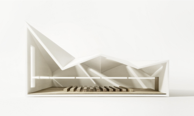
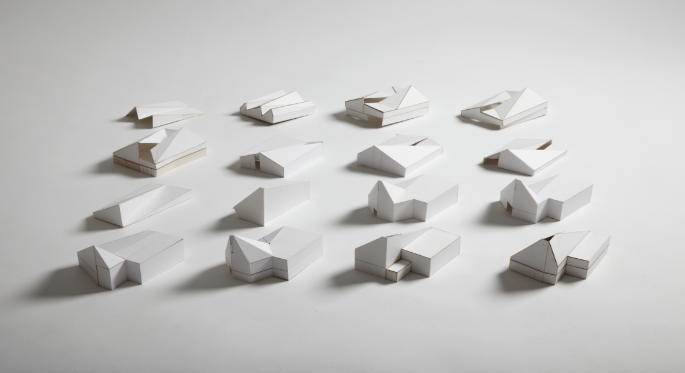
FORM
Development
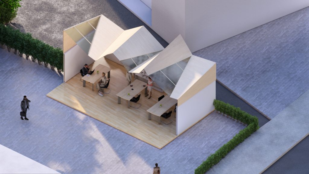
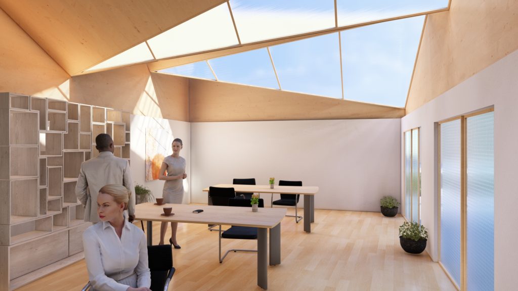
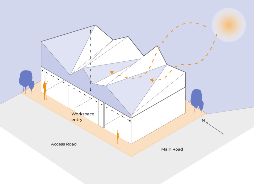
Our design vision integrates folded plate trusses for expansive spans, enhancing both function and aesthetics. Orienting longer sides towards the south optimizes natural daylight penetration, fostering a bright and inviting interior ambiance. By eliminating linear beams and incorporating folding plates internally, we achieve a heightened sense of space and elegance. Strategically minimizing front and rear openings ensures a serene environment shielded from external noise, promoting tranquility and focus. Rapid on-site assembly with prefabricated components not only expedites construction but also minimizes waste, aligning seamlessly with our commitment to sustainability and efficiency.
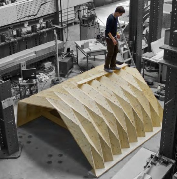
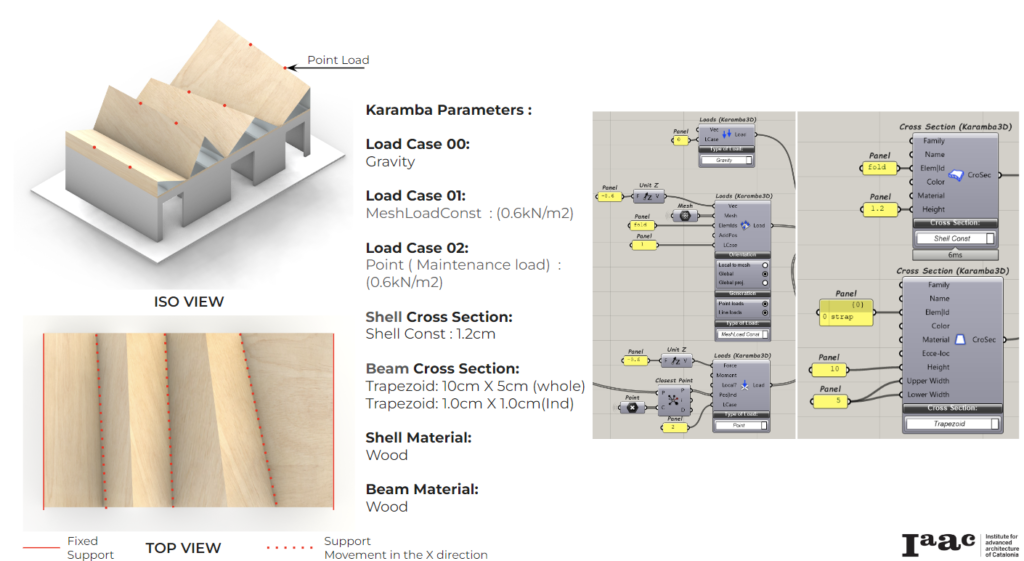
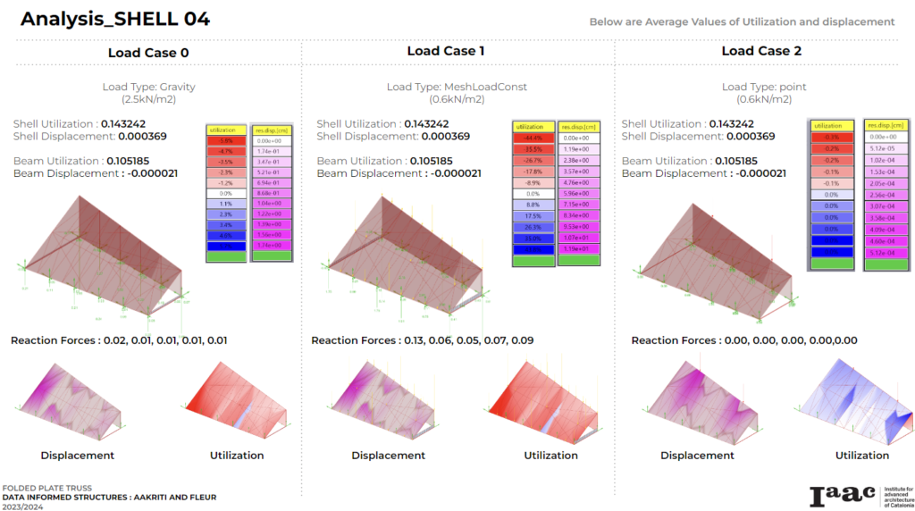
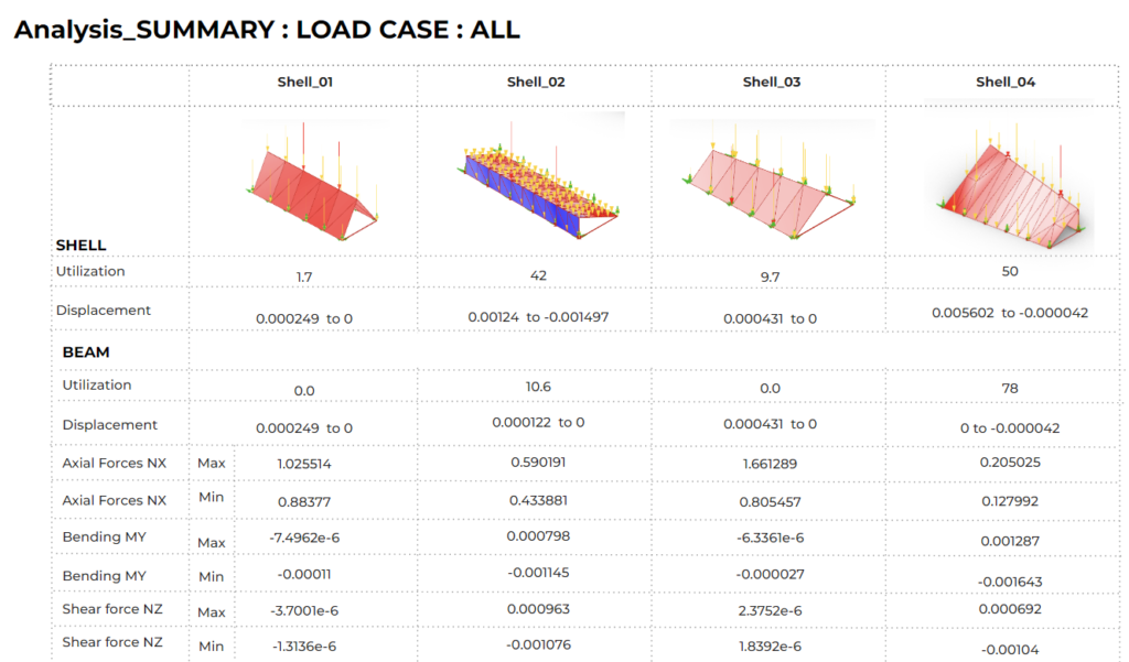
TESTING


3D ANALYSIS
Analysis


VARIATIONS IN SUPPORT SYSTEM
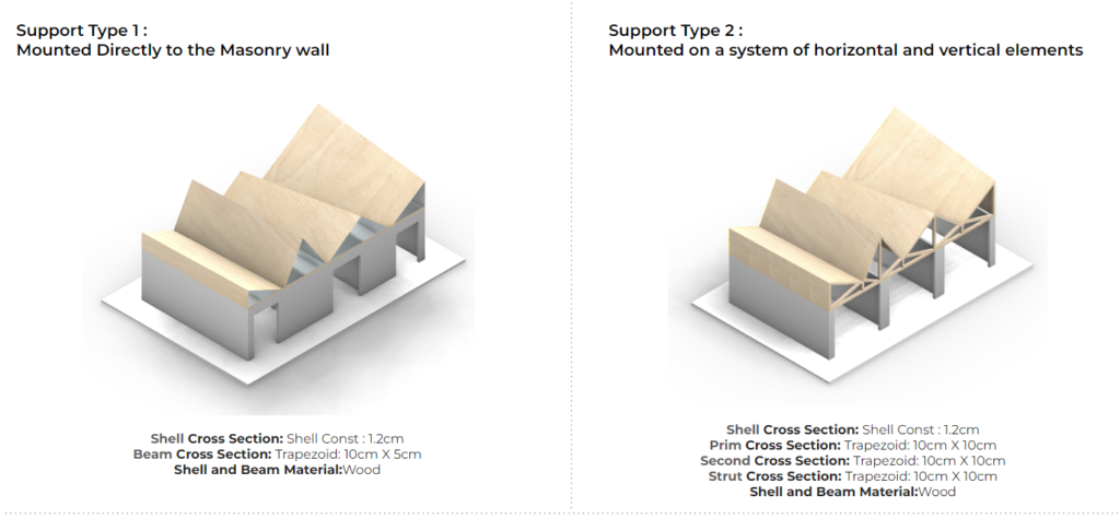
The objective was to assess the efficacy of the support structure. In the first scenario, we examined the robustness and practicality of installing the truss directly onto the masonry wall. For the second scenario, we endeavored to integrate a network of beams and struts to provide support for the truss, elevating it by 1 meter.
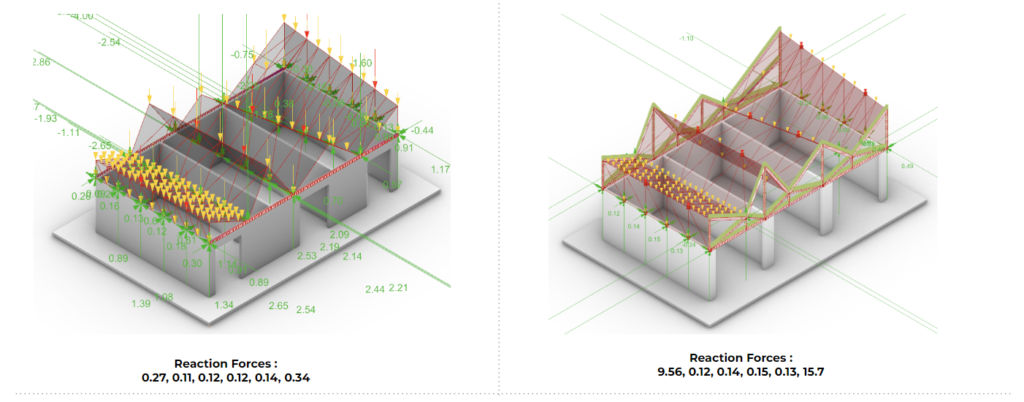
Variations Load Case: ALL
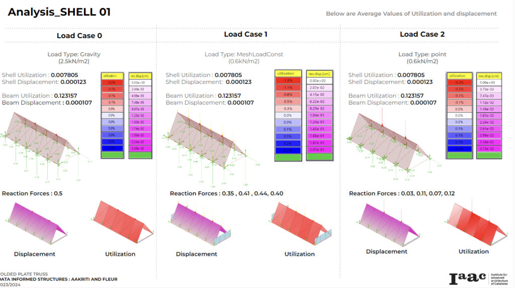
In comparing the reaction forces between the two scenarios, notable differences emerge. In the first scenario, the reaction forces are relatively lower, ranging from 0.11 to 0.34. Conversely, the reaction forces in the second scenario exhibit significantly higher values, spanning from 0.12 to 15.7.
This discrepancy in reaction forces signifies a distinct difference in the structural behavior between the two supports. The first scenario, with lower reaction forces, suggests a more stable and balanced structural configuration. On the other hand, the second scenario’s higher reaction forces indicate greater loads and potentially more stress on the structural elements. This could imply a need for additional reinforcement or adjustments in the structural design to ensure stability and safety.
The shell utilization in the first scenario ranges from 0.473 to 0, indicating that the shell elements are also operating below their maximum capacity. The shell utilization in the second scenario ranges from 0.454 to 0, indicating that the shell elements are also operating within acceptable limits but are being utilized slightly more compared to the first scenario.

the comparison reveals that the second scenario places higher demands on the beams in terms of utilization and stress levels, particularly in terms of axial stress. This indicates a potentially more demanding structural configuration in the second scenario, which may require closer attention to ensure structural integrity and safety.
The shell displacement in the first scenario ranges from 0.005657 to -0.000055, indicating slight movement or deformation of the shell elements. The shell displacement in the second scenario ranges from 0.001309 to -0.000921, indicating slightly higher levels of movement or deformation compared to the first scenario.

The comparison reveals that the second scenario experiences slightly higher levels of displacement and stress in the beams and shell elements compared to the first scenario. This indicates a potentially greater structural response to applied loads in the second scenario, which may warrant further analysis to ensure structural stability and safety.
CONNECTIONS

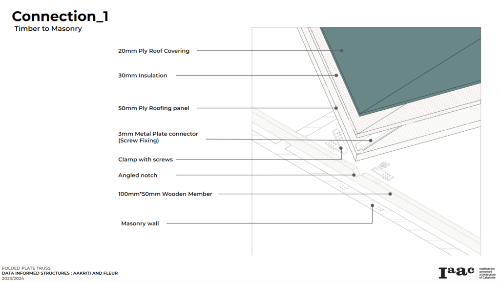
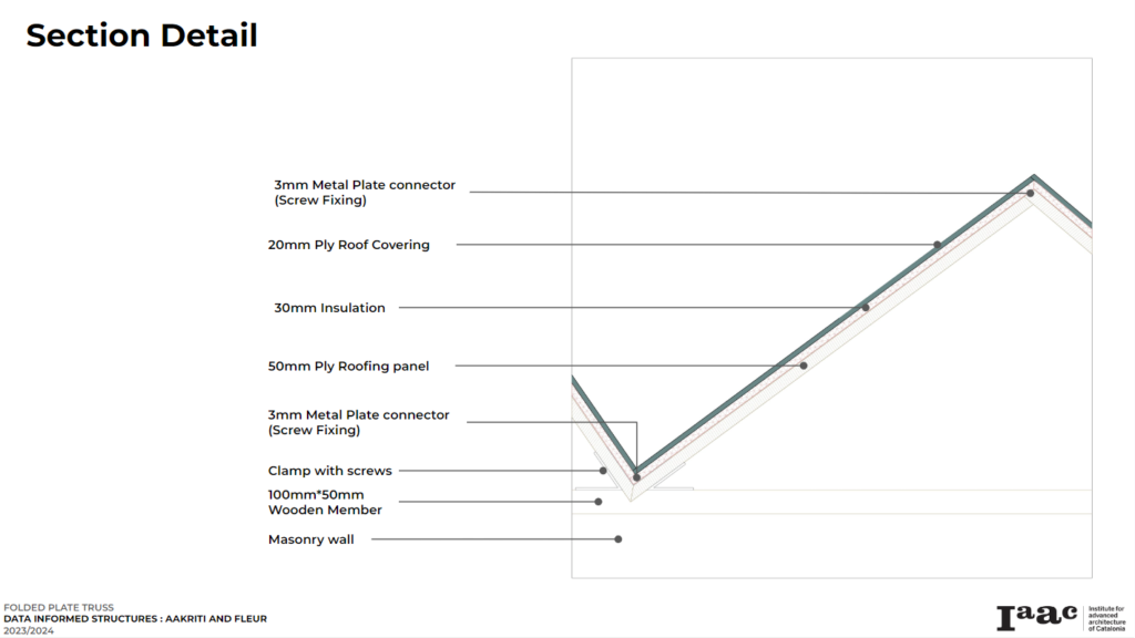
ASSEMBLY
Case Study : Temporary chapel for the Deaconesses of St-Loup
In the summer of 2007, Local architecture and architect Danilo Mondada were awarded the contract to renovate the mother house of the Deaconess Community of St-Loup. The commission involves the complete renovation of a historic building, including the community’s main chapel.
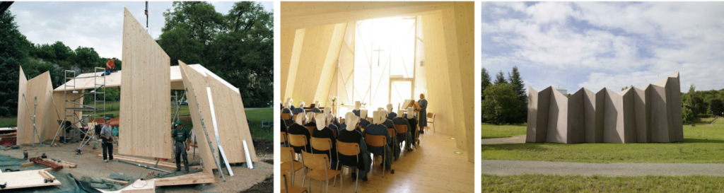
The St-Loup chapel, nestled seamlessly into its surroundings, boasts an innovative design that harmonizes with the landscape. Its east-west orientation invites ample natural light, while origami-like folds create dynamic variations in space. Beginning with a wide horizontal entrance, the structure gradually rises vertically towards the chapel’s center. Transparent plastic panels, covered with fabric, infuse the interior with natural light, echoing the frame of columns reminiscent of stained-glass windows. This pioneering wooden chapel, marrying computer-generated geometric forms with traditional religious space, exemplifies a modern reinterpretation in perfect synergy with its environment.
CONCEPT VISUALIZATION