Designing for the 3D printing of a self-supporting Pavilion
Background
For the Competition phase, the brief asked for a design of geometries that addressed the 5th facade in the attempt to cover or go over and above the average human height. Our proposal attempts to have this brief satisfied without the use of additional/external support and will therefore only rely on the self-supporting abilities of the eventual geometry. A print length limitation of 4500m was also set in the brief, as well as a roofing proposal.
…………………………………………………………………………………………………………………………………………………………………………………………………………………………………………………………………………………………………………………………………………….
Base Geometry Development
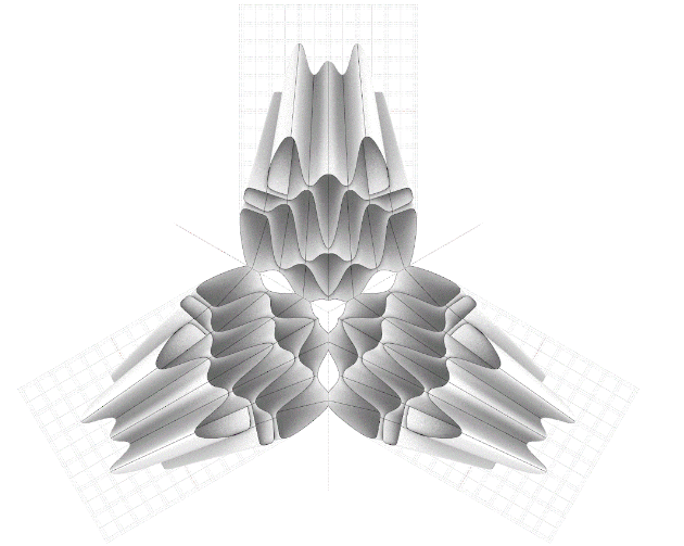
To achieve the said goal, iterations of geometry surfaces were considered and the set of principal arches were extracted from the base geometry surface. These set of principal arches were analyzed to find the appropriate angle of inclination allowing necessary overlap between the successive layers.
1 vs 3 axis of symmetry
Inclination
…………………………………………………………………………………………………………………………………………………………………………………………………………………………………………………………………………………………………………………………………………….
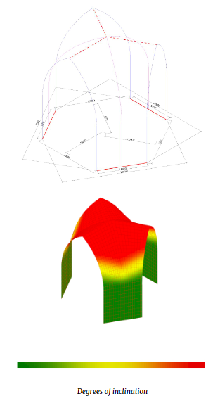
Inclination Analysis
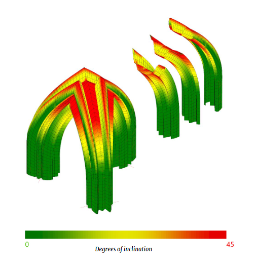
In order to anticipate successful printability of layers during printing, the selected geometry was analyzed for its degree of inclination, with green indicating lowest angles of inclination and red showing the highest. In the image above, the green sections of the geometry are considered safe to print as they ensure maximum overlap of layers during printing. The red zone indicates a reduction of layer overlap, which is considered risky for printing.
The simulation below shows the inclination angle needed to improve the printability of the arches.
…………………………………………………………………………………………………………………………………………………………………………………………………………………………………………………………………………………………………………………………………………….
Final Base Geometry
Two base surface geometries were developed – one with three supports and another with four supports. Those two geometry were used to create a small catalogue of final geometries that incorporated infill patterns. Finally, the geometry with 3 supports was preferred since it generated a lower surface area, meaning that the total mass of the resulting structure as well as the total printing time would be reduced.
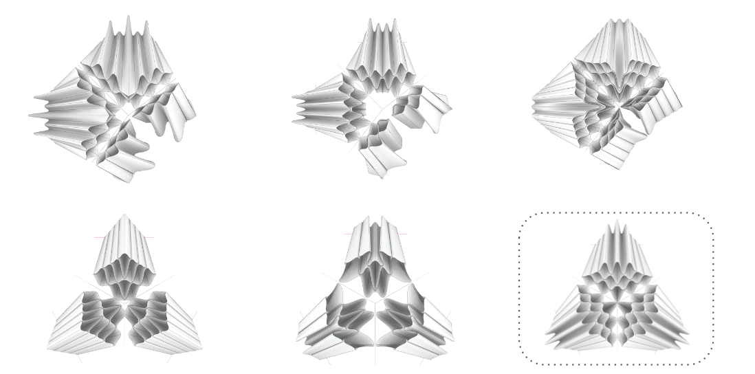
1 vs 3 axis of symmetry
…………………………………………………………………………………………………………………………………………………………………………………………………………………………………………………………………………………………………………………………………………….
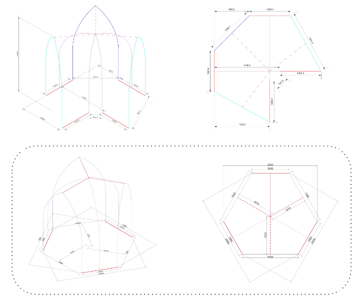
Parametric Development
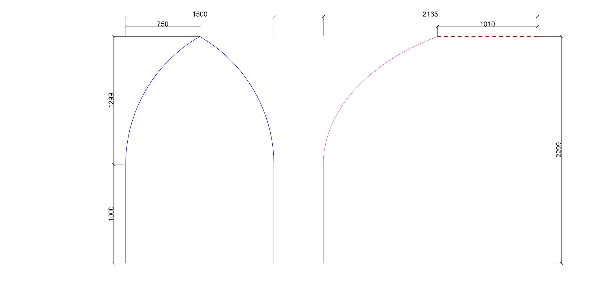
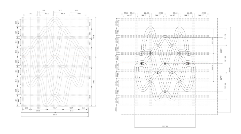
The plans below show the projection of the arches to understand the guiding design principles of the base geometry. The design brief required vertical walls of 1 metre in length (a), with a straight extrusion of at least 1 metre. This is indicated by the red broken line in the drawings below. ration of the wall length to the arch height. These walls are placed in a way that their centers align with the mid-points of the wall axis shown. The length of the lines (b) connecting the endpoints of the walls become the bases of the arches. The formula shown below guides the rest of the geometry development.
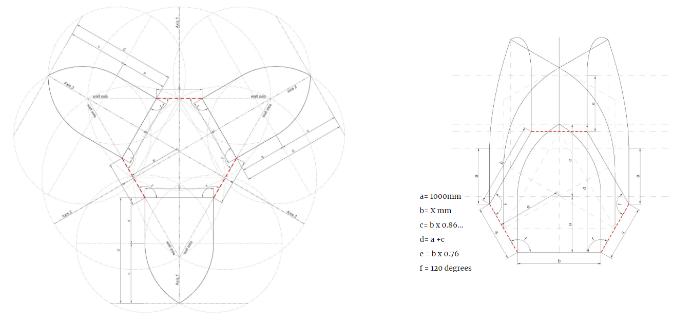
Development strategy
…………………………………………………………………………………………………………………………………………………………………………………………………………………………………………………………………………………………………………………………………………….
Infill Design
The image below on the left shows the initial development of the infill pattern, which was further modified to allow for continuous printing and manage layer overlaps and connection points between infills. Infill overlaps were guided and kept at half of the layer thickness.
From discontinuous to continuous
The infill patterns grow along the rails of the designed arches to form the three supports that meet and join at the top, completing the geometry. This connection makes the geometry more stable. The geometry was further analyzed for it’s degree of inclination to understand the risk of collapse due to inclination. The simulation indicated that the three supports would connect to each other before the point of failure of individual supports due to the inclination at the red zone.

Geometry analysis
Inclination
Analysis of the Center of gravity of one support to understand the maximum printable angle
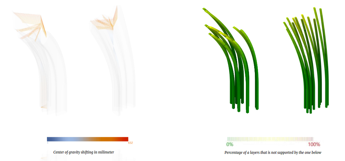
Center of gravity & slicing analysis
…………………………………………………………………………………………………………………………………………………………………………………………………………………………………………………………………………………………………………………………………………….
Development of Final Geometry
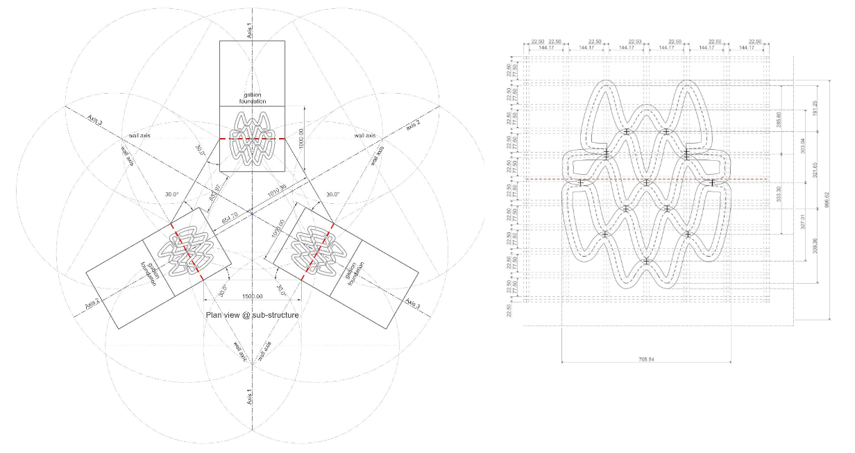
Foundation Plan
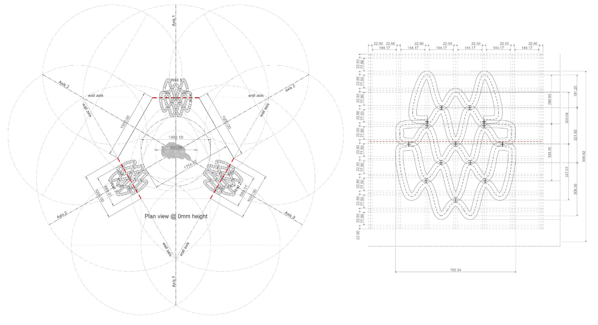
Plan view at 0 -10mm
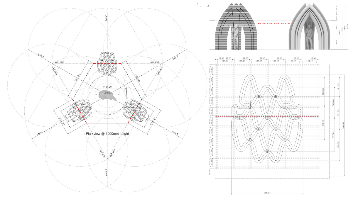
Plan view at 1000mm height
Plan info:
Number of layers: 5
Layer thickness: 45 mm
Slicing distance: 1.5mm
Infill contact points: 12
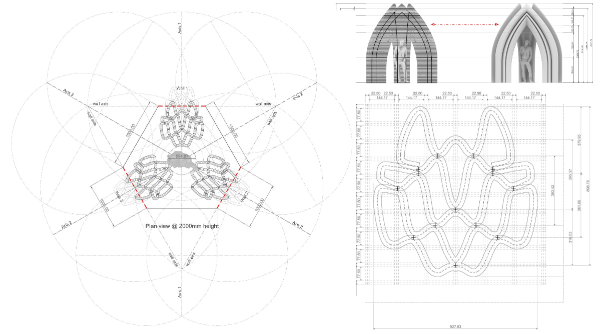
Plan view at 2000mm height
Plan info:
Number of layers: 5
Layer thickness: 45 mm
Slicing distance: 1.5mm
Infill contact points: 12
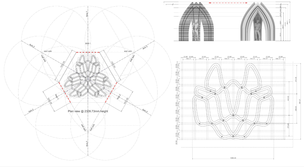
Plan view at first point of connection =2309mm
Plan info:
Number of layers: 5
Layer thickness: 45 mm
Slicing distance: 1.5mm
Infill contact points: 12
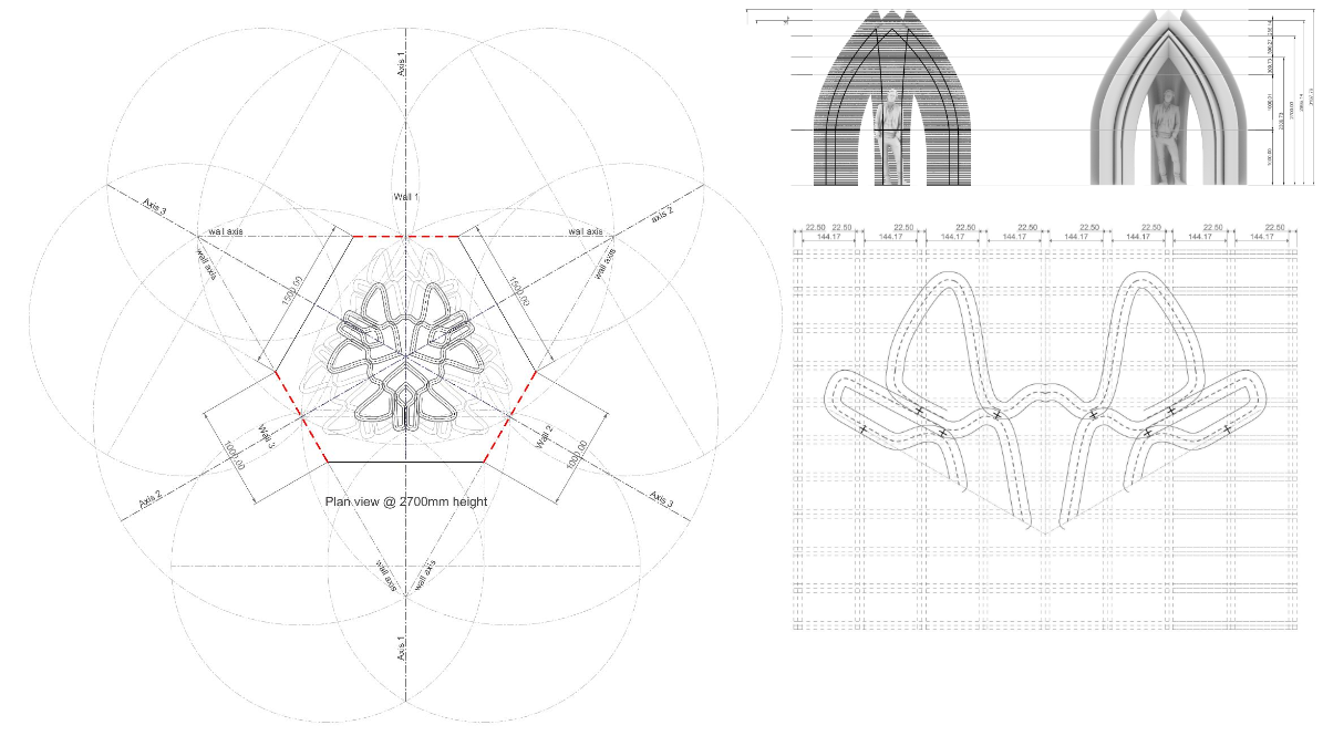
Plan view at 2700mm height
Plan info:
Number of layers: 5
Layer thickness: 45 mm
Slicing distance: 1.5mm
Infill contact points: 6
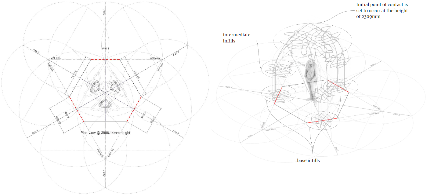
Plan view above 2900mm
Contact points are maintained throughout the geometry
Arches connection
…………………………………………………………………………………………………………………………………………………………………………………………………………………………………………………………………………………………………………………………………………….
Prototype
The geometry was then put to the test at a scale of 1:20, using the available desktop printers. As earlier anticipated, printing went on smoothly and there was little risk of failure for the most part. However, as the angle of inclination increased, the risk of collapse grew, but as earlier seen during the analysis, the three legs of the geometry joined together early before the anticipated point of failure, and the geometry became even more stable once the joint was achieved.
Geometry analysis
1:20 clay print
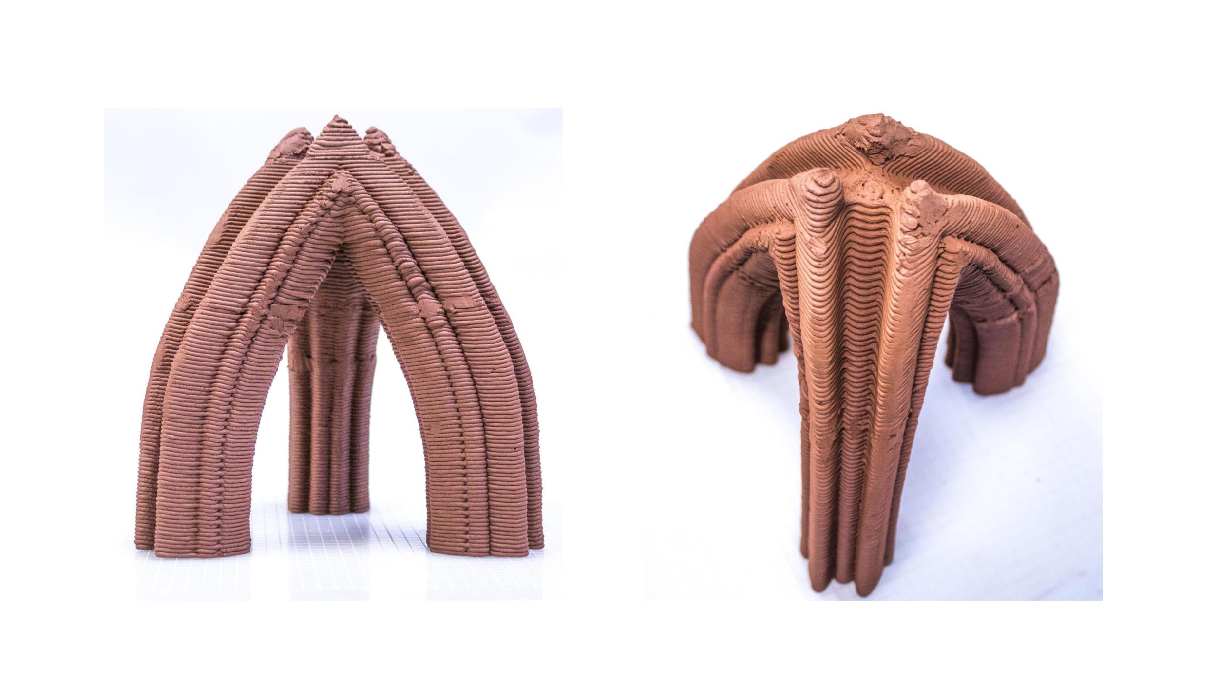
1:20 clay print
…………………………………………………………………………………………………………………………………………………………………………………………………………………………………………………………………………………………………………………………………………….
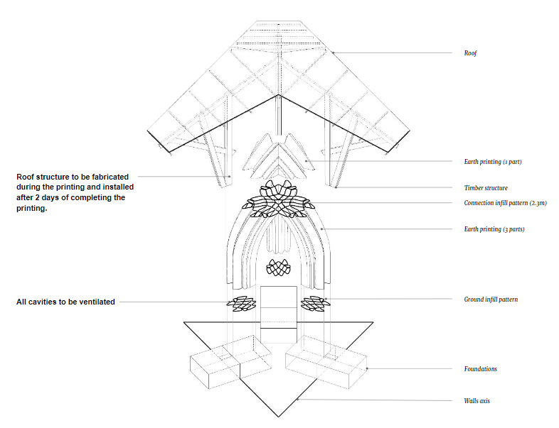
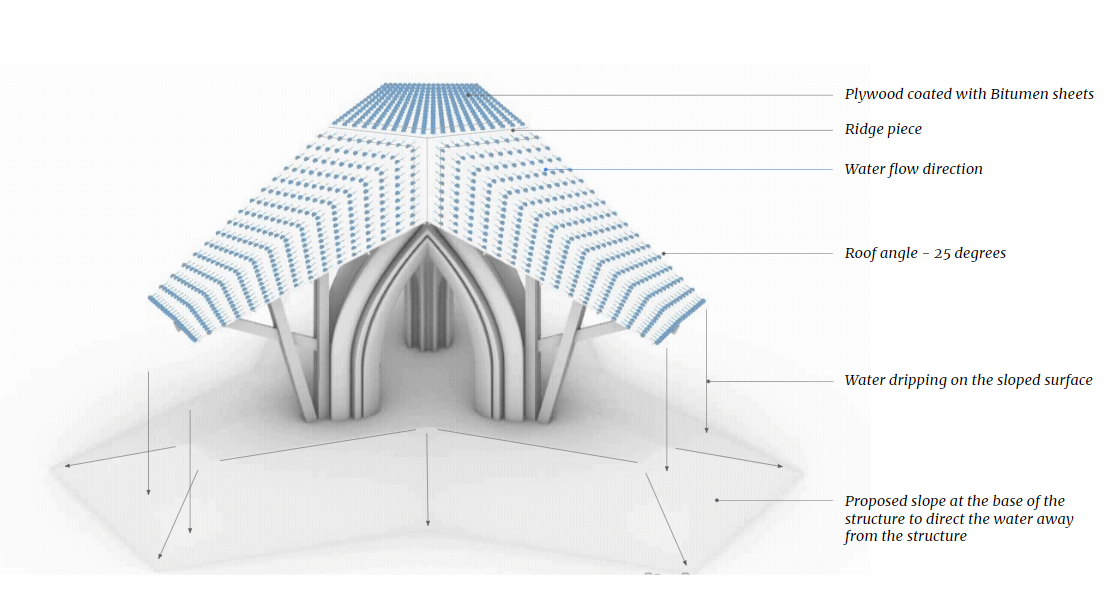
Roof Design
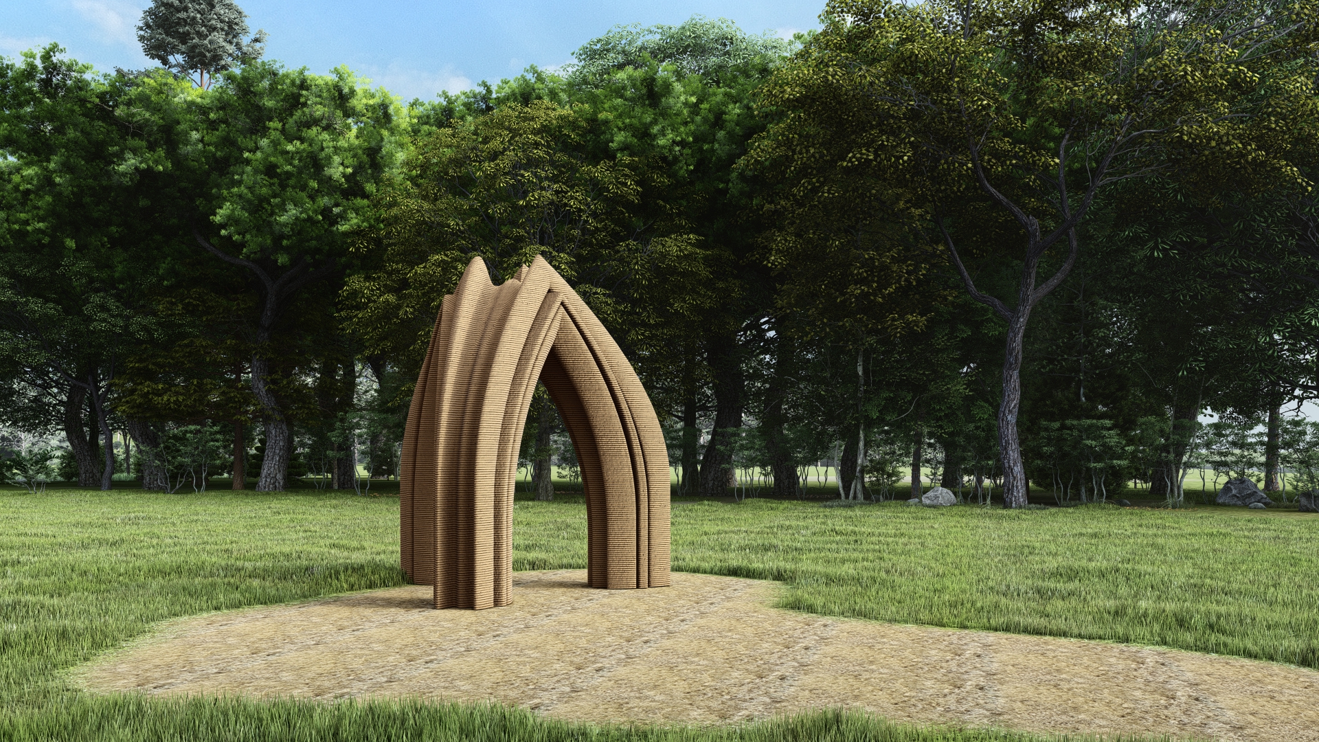
The roof is designed to ensure the complete view of the earth printed structure and protection from the rains. The roof slopes at 25° angle and diverts rain water away from the structure. A gradual slope at the base is provided to direct the rain water from the roof away from the base.
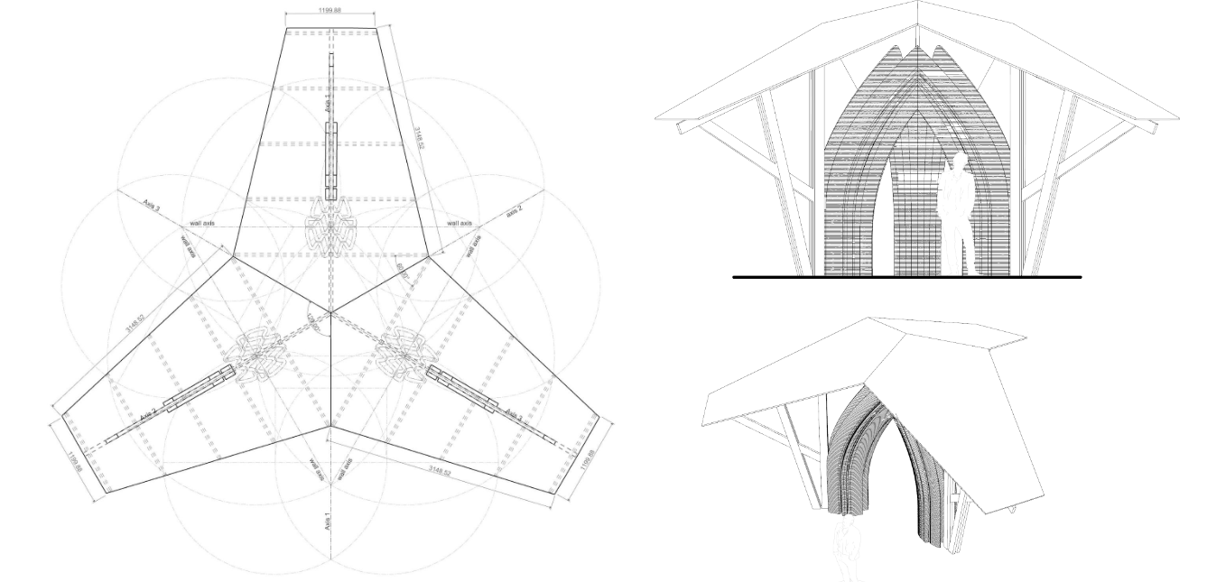
Since the roof is disconnected from the earth structure, the fabrication of the roofing members can be done as the printing process goes on and the roof can be installed within a couple of days after printing.
…………………………………………………………………………………………………………………………………………………………………………………………………………………………………………………………………………………………………………………………………………….
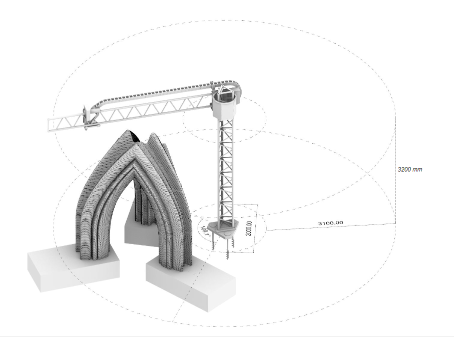
Site Organization and Crane Positioning
Positioning
The structure is placed within the printable area of the WASP crane to understand the feasibility of printing. As seen below, it fits well within the printing area, and is therefore printable by the crane.
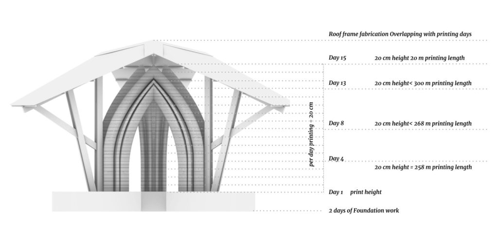
Printing Schedule
The total printing length of 3800m was divided into a number of days. 20cm per day of printing is considered totaling to 15 days of printing. The printing per day is between 250 to 300mm for first 10 days and decreases to 100 mm and below as printing progresses towards the end, to mitigate risks of collapse. The critical days where most risk is taken is right before the 3 supports attach at the top. The risk is reduced after the successful connection of the 3 supports.
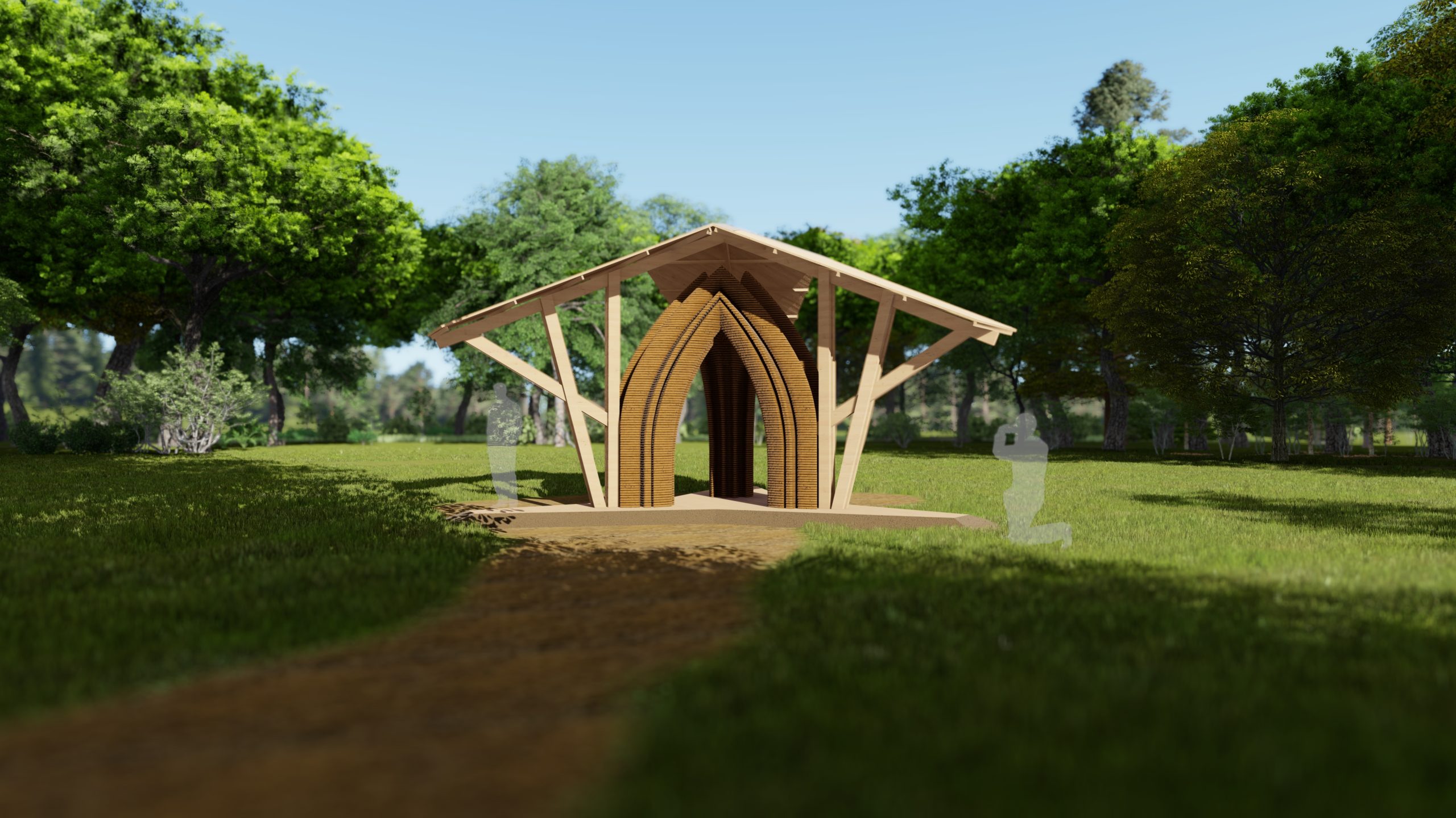
Exploded View and Renders