
Brief & Design Concept
The integrative design assignments aim to aid the studio project so that the work involved and the outputs can be utilized for the final studio pinup. The brief of this project is a hyperbuilding design in Tokyo with a GFA of 1 million SQM. The concept established for the project encapsulates the philosophy of archology, a term coined by Paolo Soleri in 1969 to describe a fusion between architecture and ecology to create efficient and sustainable urban environments that maximize population density while minimizing the impact on the environment.
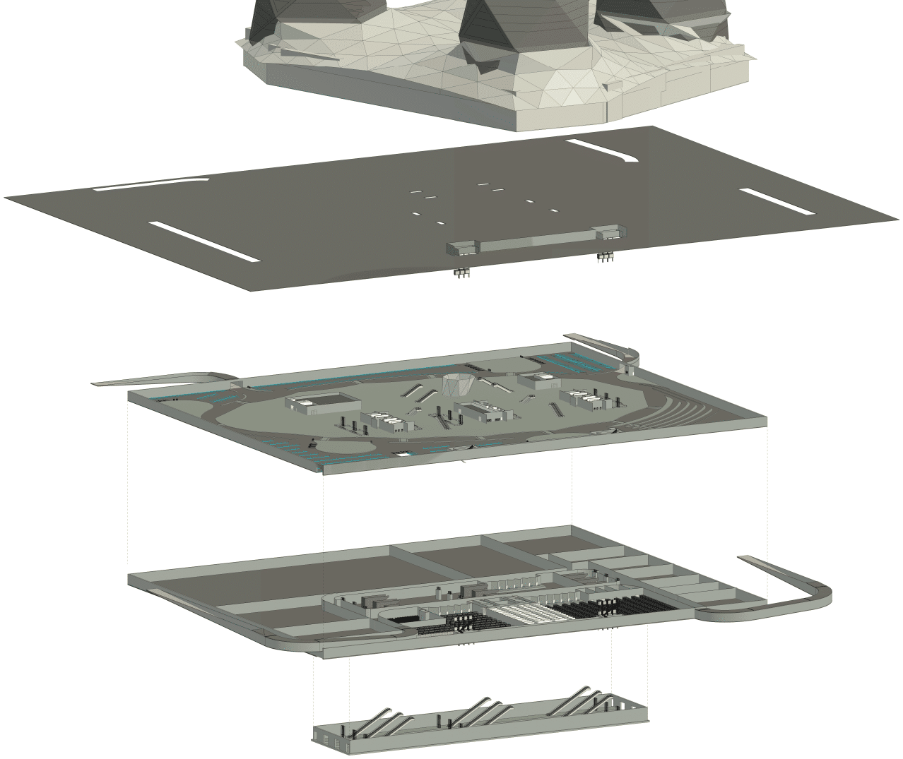
It is a group project (group of 19), where our team (of 4) is responsible for the industrial scope. Aligning with the overarching concept, this is interpreted to involve the food production, energy supply, mobility, and smart manufacturing aspects of the design. Over the evolution of the design the building took shape as a below-ground podium, an above-ground podium (retail plaza) and 4 residential towers housing 10 thousand residents. The industrial scope is housed in the below-ground podium in 3 levels:
- B3 – Train Tracks and Platforms
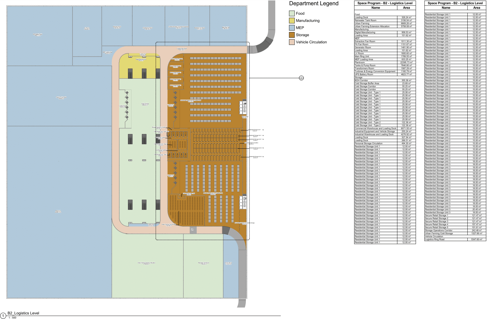
- B2 – MEP spaces, manufacturing spaces, urban farming spaces and logistics spaces
- B1 – Bus and Taxi concourse
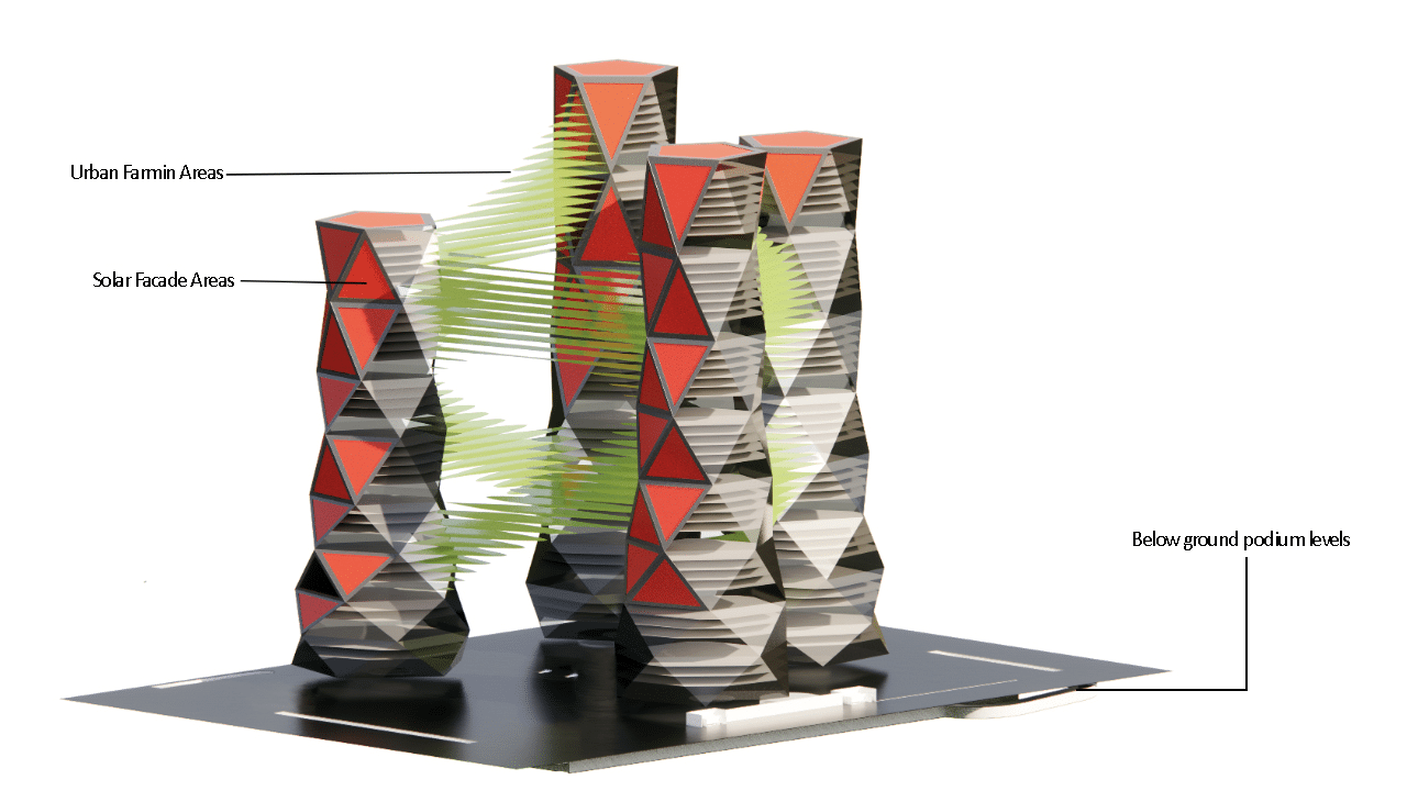
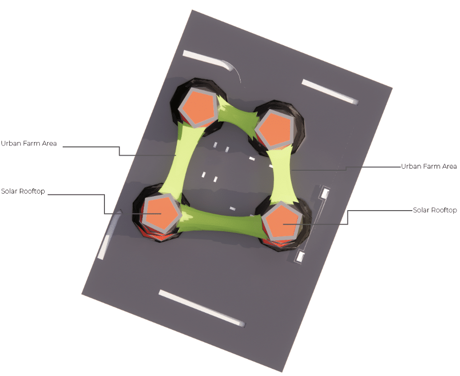
In addition, the bridges connecting the towers house the hydroponic and aquaponic systems for vertical farming, and solar energy harnessing via facade and roof panels.
Software Ecosystem
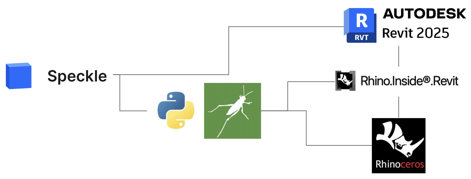
To deliver this scope, we have chosen a combination of several platforms and plugins. The design authoring used both Revit and Rhino + Grasshopper from the onset, while Rhino Inside Revit and Speckle handled the interfaces between platforms. The project coordination and data reporting was also done via Speckle into a single Hyperbuilding Speckle project governed by the Data Team.
Podium
Since the below-ground podium part took a rather traditional shape and only the design optimization used Rhino and Grasshopper workflows, the design of this part started in Revit straight away. The early design phase involved establishing the KPIs for the design, and confirming requirements for the scope of each design team. This was a collaborative space programming exercise, basically a lot of tinkering over identifying zoning, space connections, and related areas. The rooms were categorized according to their function in the ‘Department’ parameter and basic Color Schemes were applied. These layouts helped the evaluation of the space program at the end of design iterations.
Bridges
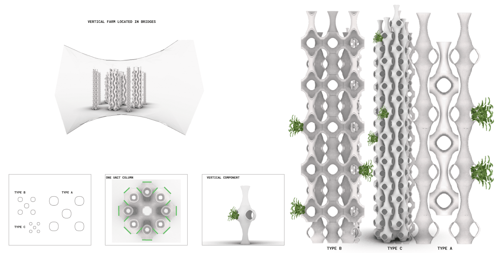
The bridges between the towers are populated with vertical farming columns. The form follows Schwarz-P volumetric meshing with millipede, the Grasshopper definition combines parametric equations, mesh generation, and data tree manipulation. The result is a spiraling, organic structure optimized for vertical farming, that maximizes growing area while maintaining an efficient, visually interesting form.
Solar Panels
Using the facade Grasshopper definition, roof areas and facade panels were identified for the purpose of solar energy generation in collaboration with the facade team during the design process. The selection considered the required energy output.
Revit Model Setup – Naming Conventions and LOD
The Revit model setup considered the explicit needs and planned output of the Studio project scope in terms of embedded design information, naming convention and LOD. Accordingly, the following measures were applied to achieve element and space categorization, information display and schedule setup:
- Family type names incorporate the related element classification as per the Uniformat II classification system and assets that are outside of the domain of this system are classified (in their Type name) as per the Product table of Uniclass.
- As mentioned further above, the ‘Department’ parameter of every Room is populated with the building function it belongs to.
- Based on the extent of embedded information required to deliver the Studio scope, in an unorthodox manner the ‘Mark’ and ‘Comment’ parameters of objects were used to host certain information that was required to configure Revit schedules to display the intended information content.
The chosen LOD also follows the explicit display requirements for elements, where the level varies between LOD 200 and 300, according to their scope: the Industrial scope is generally modeled in enhanced detail. In some cases, very detailed families were used as the intention is to use these models to generate the render images for the Studio presentations.
Model Content Integration
At the production stage, the design content is integrated into Revit using Rhino Inside Revit. This brief video demonstrates the transfer and data integration process from Grasshopper into Revit:
Finally, this workflow video showcases our innovative use of Speckle combined with Power BI as a powerful filtering tool. It illustrates our process: data moves smoothly from Speckle to Grasshopper, scripting within Rhino.Inside generates customized Revit families, and geometry is directly transferred from Speckle into Revit. This demonstrates the broad potential and efficiency gains achievable through integrative modeling workflows.
Summary
The modeling techniques utilized were selected and applied based on a fit-for-purpose approach – we have tried to use each application explicitly for those steps in the process where they are the strongest and with whom we can achieve the best quality result with the least amount of effort. The deliverables for the Studio presentation determined the graphical and textual information content embedded in the models and the method we structured them inside. As a result, we managed to extract such outputs that require minimal post-production efforts for our final presentation of the project.
