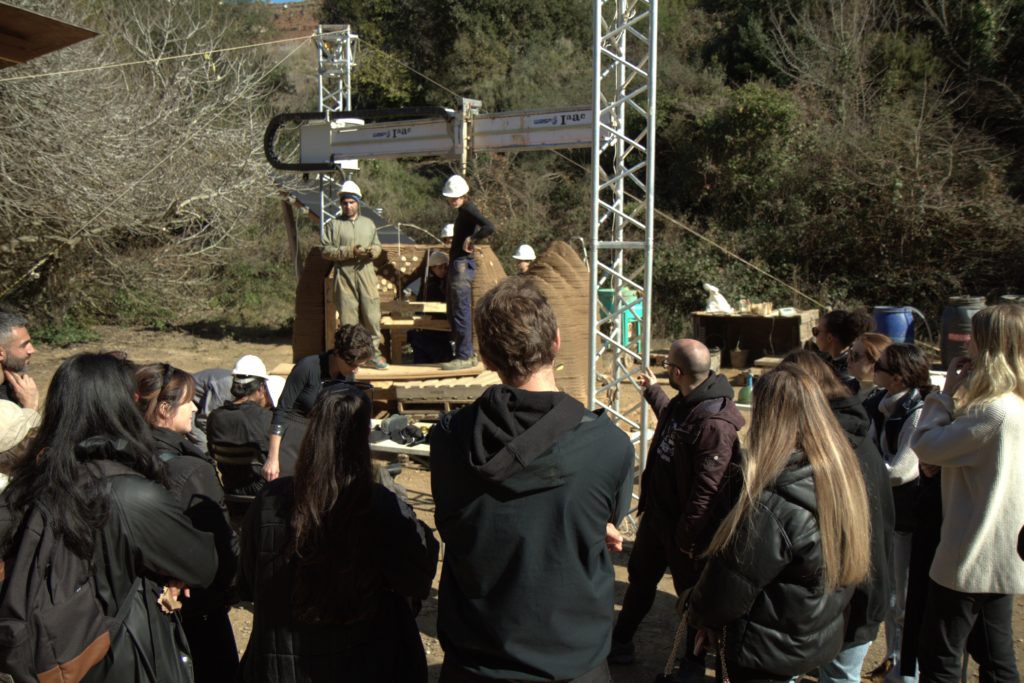
The use of large-scale 3D printing in construction has been on the rise in recent years, with many architects and builders experimenting with different techniques and technologies. One such project is the final project for the 3DPA postgraduate program at the IAAC Institute for Advanced Architecture of Catalonia, which utilized the WASP Crane for printing a large structure. This article will detail the construction of the project, including the strategies used for printing, the materials used, and the challenges faced during the process.
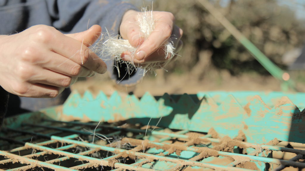
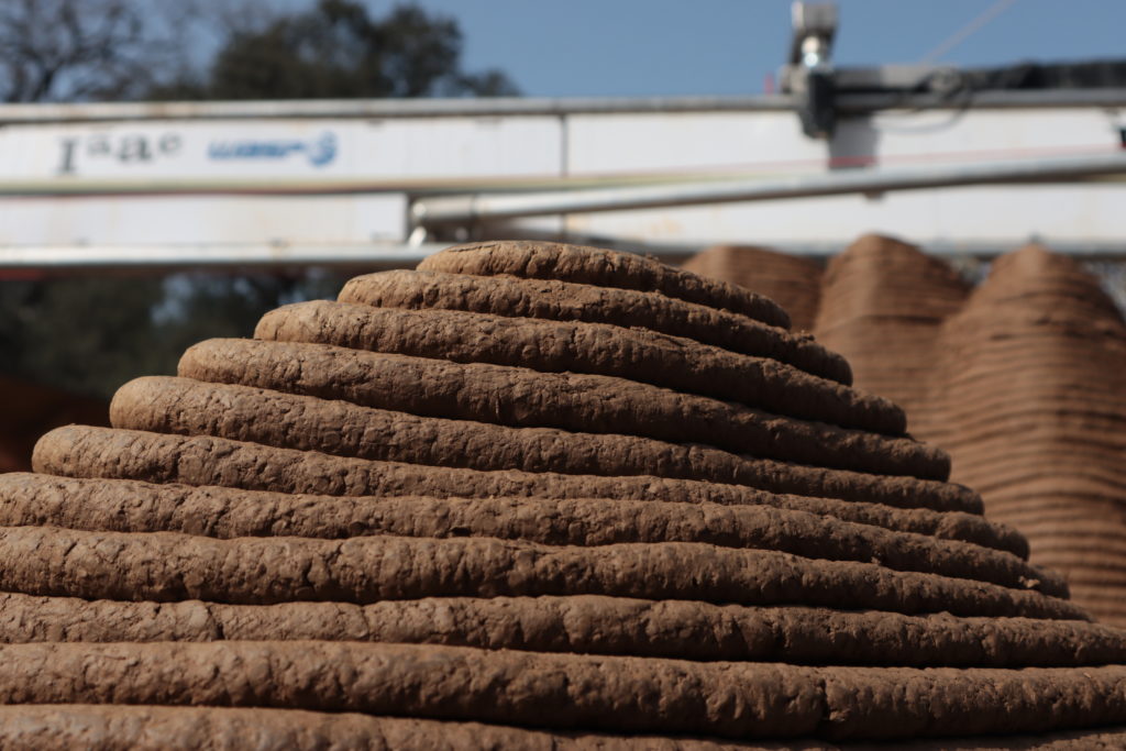
The WASP Crane is a large-scale 3D printer capable of printing structures using a variety of materials. In this project, the team used the Crane to print the foundation cast of a building and a double vaulted geometry using a mixture of earth, sisal fibres, gravel, water, and geopolymer for enhancing the strength and hydrophobic qualities of the foundation.
The geometry
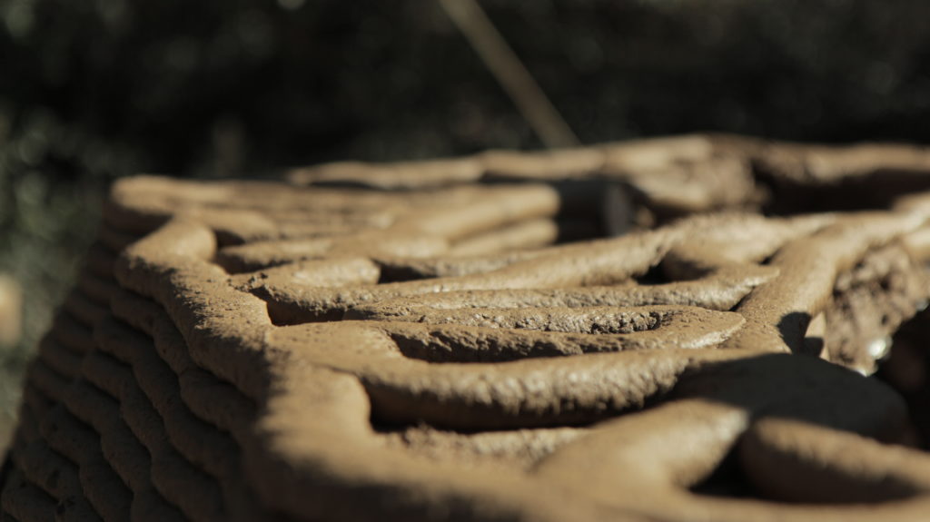
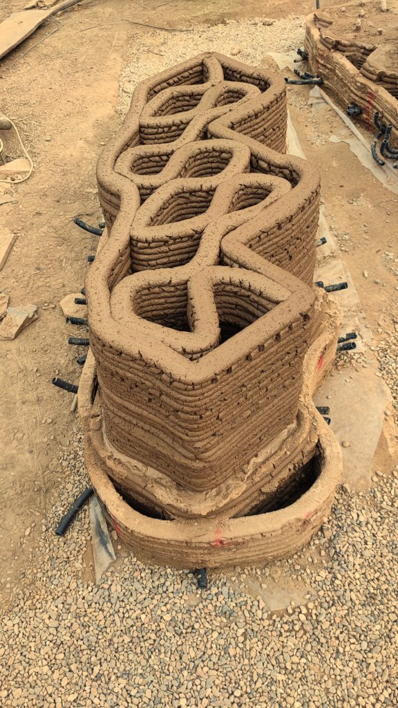
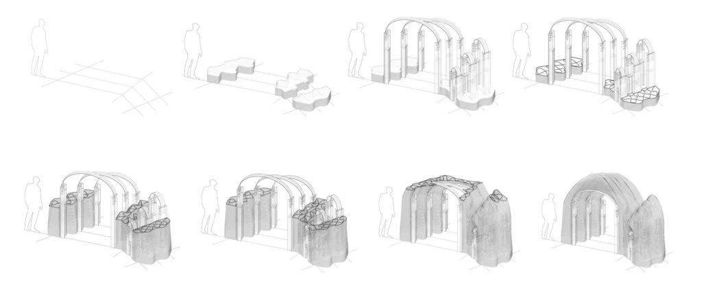
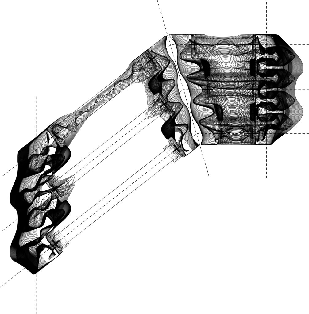
The aim of the programme was to achieve the fifth facade, a demanding topic that required various active geometrical strategies and passive strategies such as active bending scaffolding and, later on, post-tensioned fibres placed in cross-sections of the print. The geometry chosen was a compilation that resulted after the completion of the competition phase. The pavilion was designed as a double vaulted geometry, composed of multiple descending arches, aiming to enclose the top of a space.
Setting up the site
3D-printing technology has come a long way since its inception, and today, it is used to build everything from small-scale models to full-size buildings. Setting up a site for the last category requires a lot of coordination and planning of the following working stations: Sifting of the locally sourced earth, Mixing and measuring the quantities of all the aggregates, Pumping, Control & Quality Control.
Log Entries from Construction Site
Week 1: Calibration and accommodation with the machine
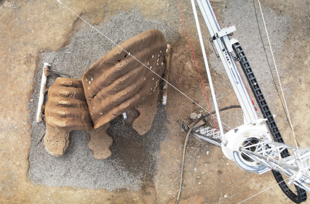
After setting up all the working stations and installing the gabions for the foundation, the installation of the robotic arm was the next immediate objective. The crane was used as an active support tool even before the actual printing moment, used for markings or tracing the path.
The first week of the project was spent calibrating the Crane and fixing some connection issues. The crane rotation calibration was set to -38 degrees. The extruder connection was also broken, but the team was able to fix it by forcing connectors on the crane box. The team also set up a home plate for X/Y=0 and Z=0, to define the home.
The team used two recipes for the earth mix: one with geopolymer and one with sisal fibre and enzyme. The first recipe consisted of 1 kg geopolymer, 2 kg earth, 2 kg gravel, and water. The second recipe consisted of 60 kg earth, 9 kg water, 0.06 kg sisal fibre, and 0.018 kg enzyme.
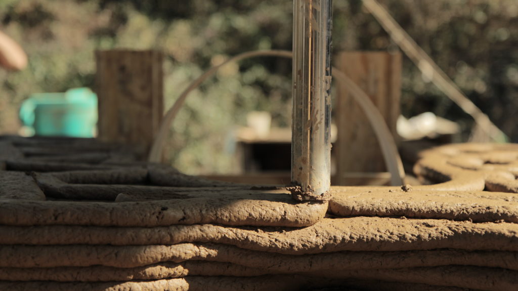
To execute the foundation, the team used the Crane to print the outlines of the foundation cast. Rebars were then tightened to the gabion mesh to reinforce the foundation against lateral movements of the structure. Finally, the geopolymer mortar mixture was applied manually in the foundation perimeter, casting the rebars and the ventilation pipes previously set up to reach every infill cavity that would be printed on top.
Week 2: Printing Strategy and Material Calculation
Building sustainable edification from locally sourced materials is a challenging task that requires a lot of coordination and effort. In the second week of the project, the team faced some unexpected challenges, but progress was made in several areas.
One of the challenges encountered was the freezing temperature, which slowed down the work. However, the team was able to use this time to fix the red line sensor of the crane, which needed to be tightened in order to be able to use the crane.
The casting of the foundation required printing the outline geometry, and the team used the same G-code for each layer and moved the Crane up 15mm after each layer was printed. The first layer was printed with a speed of 40 to 50%, an E rate of 150% to 190%, a pump of 2.6, and a height of 15mm. The second layer had a height of 10mm to ensure proper levelling.
The team also calculated the amount of earth and geopolymer needed for the project. For the earth material, the length per layer was 38m, the length of 20 layers was 76m, the area of the path was 0.000675 m2, the volume of one layer was 0.02565 m3, and the volume of 20 layers was 0.513 m2. For the geopolymer material, the area was 3.328 m2 and the volume at 0.30m height was 0.99 m3.
However, the team encountered some issues during the printing process. There was frozen earth inside the crane nozzle, which was to be checked in the morning and added to the end of the day’s task. The balancing motion of the top of the extruder could also be from the bend of the aluminium plate under the rubber, but this needed further development.
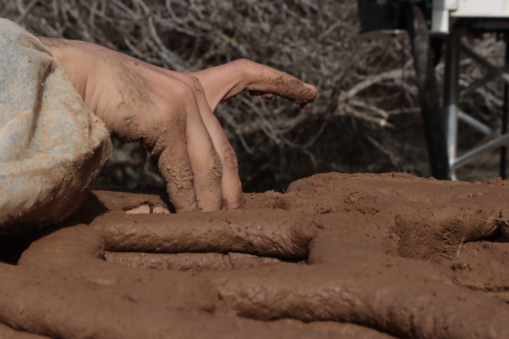
Progress was also made in the mixing of materials. It was discovered that adding 0.5 litres of water to the mix improved the extrusion process. The team used 60 kg of earth, 10 kg of water, 0.06 kg of sisal fibre, and 0.018 kg of enzyme for the mix. It was important to spread the fibres as much as possible to avoid clumps of fibre getting stuck in the pump during cleaning.
Printing was started at a layer height of 30mm, and while the extrusion was generally smooth, a few breaks were encountered that required certain lengths to be redone. The team found that the printing station worked most efficiently with a team of five people: one person to handle the computer, one person to measure the materials, two people to mix the materials, and two people to handle the pumping. It was also found that having a sixth person to document and provide an extra hand was helpful for handling unforeseen situations like breaks during printing or controlling the wind.
Before pouring the plinth elements, the team marked the ventilation tubes and positioned the metal reinforcement structure, but the tubes were not yet fixed in the correct position. The chemical anchoring foundation rods were applied with epoxy to anchor and seal them along with the hydrophobic sheet. Foundation rod spacers were filled with soil mix to avoid air bubble stacks inside the poured geopolymer, which could result in cracks.
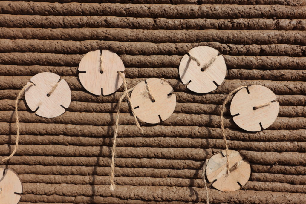
Ventilation tubes for the walls were also installed. Wooden plates were perforated exactly where the holes needed to be according to the infill’s drawing, and the same number of pipes should be matched to the number of holes in the wooden sheet. Longer pipes should be used for easier connection to the ventilator fan.
A wooden jig was prepared by marking the points using the WASP crane and cutting the ply sheet to create a slight geometric lock. The ply was cut manually with reference to the outer infill print and then divided into three pieces to make it easier to install pipes and work with geopolymer.
Pouring the foundation and keeping all the ventilation tubes in place was arduous, so a later recommendation would be for this wooden jig to be milled in advance in the lab, instead of the site, cut mimicking with high fidelity the first layers of infill geometry, as a positive wooden replica.
The team completed the geopolymer basement work for one of the three parts, using a ratio of 1:4:3 and consuming two bags of geopolymer. The geopolymer mix consisted of 27 kg of water, 37.5 kg of gravel, 50 kg of earth, and 1/2 bag of geopolymer (12.5 kg). The last batch for the foundation was more viscous, with 30 kg of water. Adding gravel and water in the first stage helped to clean the mixer and create a more coherent mixing process.
One of the challenges encountered during printing was how to protect the structure and the roof from heavy winds. The team left the crane arm stabilized over the print to prevent the blue tarp from tearing off and falling over the print, but a better strategy needs to be developed in the future.
Overall, the team made significant progress in printing the foundation using the WASP Crane. With further refinement and development, the Crane has the potential to revolutionize large-scale construction.
Week 3: Active bending prototype
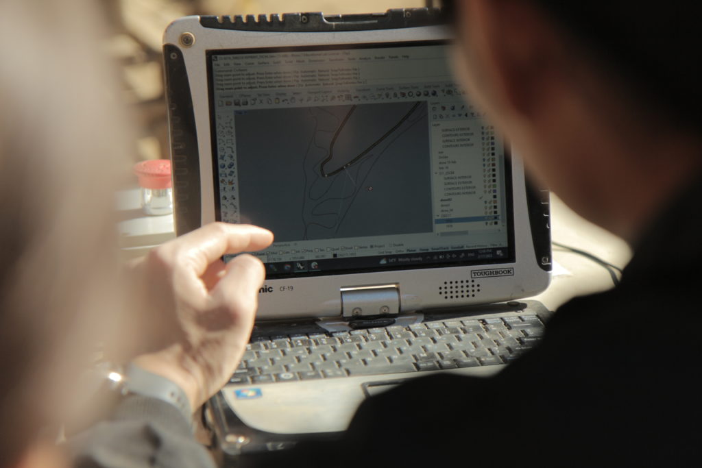
The active bending prototype was designed to be a flexible and lightweight structure that could be easily transported and assembled on-site. The set-up of the pieces has been constantly updated and the coordinates were implemented in the model Rhino file as well, being a medium of communication and a collaborative workflow between the print design and joinery fabrication while installing the pieces on site.
Week 4: Challenges and Solutions
One of the challenges the team faced was geometry. The tarp protecting the printing site from the elements had damaged the edges of the geometry, and the crane had to be rotated due to strong winds. To generate the G-codes, each wall had to be rotated in the file. Additionally, to avoid double lines, the curves of the contour had to be clean.
The crane also required troubleshooting. In one instance, three layers had to be left out for the next day due to constant troubleshooting of shifting in the X/Y plane. The team adjusted the crane radius between -37 and -38 and moved the crane closer to the starting point using the Crane calibration Grasshopper file to avoid collision with the wooden arches while travelling between the geometries. This aspect was automated later in Grasshopper while slicing the geometry and exporting the G-codes. The team also had issues with Z height in the same layer, possibly due to the loose anchoring in the ground points.
The team encountered hardware connection issues with the crane, losing the communication connection facilitating the movement in the X/Y direction and later the Z direction. Fortunately, unplugging and plugging in the wires in the main electrical box solved the problem. Every time, the machine needed to be homed X/Y and restart the Z assignment and move, before launching the G-codes. An important conclusion was made during this week, is worth spending 1h first thing in the morning to home/check/recalibrate if necessary and ghost print – target: to home only once a day to avoid shiftings after every homing.
Active bending was also an issue, and the team had to glue strips together for future use. The team had to test whether a single or double strip would be used. If double, pre-bending was necessary, adjusting tension every few hours/30 minutes. The team also needed to laminate the strips to extend them beyond 2.4 meters and test if the arch would flatten down to the desired position.
Despite the challenges, the team was able to achieve the desired number of layers this week, after reprinting altered layers due to toolpath shifting. The project required adjustments and manual support in the cantilever part between the wooden supports. The team used a print speed of 30-60% and an extrusion value of 140-180%. Also adjusted the amount of water in the mixture, between 10-12 kg, depending on the time of day and sunlight exposure.
Week 5: Valuable records
By this moment we approached probably the most challenging period in the construction phase, reaching the steepest cantilever angles and the heavier weight on top of the active bending scaffolding system. Because cracks started to appear on the key of the smallest arch, the bent wooden piece beneath was detensioned with a small step.
While the smaller arches were slowly and gradually released from the support, approaching the biggest vault, a single period of the inner wall collapsed. The failed period was re-designed to enhance stability and reprinted. Areas, where the surfaces lacked global and local inertia, were reinforced with post-tensioned fibres applied in the surface area of extreme angles of the arches. Post-tensioned meaning that the fibres were manually put in place in a cross-section of the infill and anchored with wooden pieces and after a couple of layers printed above them, the tensioning starts. This strategy holds the surfaces in place while in the wet state, the surfaces being identified previously through a risk assessment by analyzing the geometry and locally, through quality control of the print.
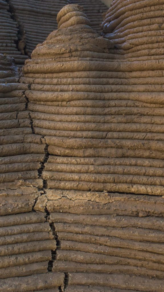
An important challenge the team faced, was maintaining the constant humidity of the material, due to sunlight and uneven drying process, vertical cracks appeared in the most prone to fissure sections of the geometry.
Due to geometrical failures, while drying, horizontal fissures appeared as well by layers being severed. This aspect invites further studies, to fully understand how complex geometries behave in a wet and dry state.
Wrapping up
The project required innovative solutions and constant troubleshooting, but despite the challenges, the team successfully completed an impressive large-scale 3D-printing structure using a WASP Crane. The Active Bending Prototype demonstrates the potential of 3D-printing technology to create innovative and adaptable geometries that can be customized to fit various environments and conditions, and the fibre system enhances the surface behaviour while printing. As the technology continues to improve, we can expect to see more exciting and groundbreaking applications of 3D-printing in construction in the future.