
Optimizing 3D Printing with AI prediction
Introduction
In this seminar we applied the concepts of machine learning to estimate the deformation during drying of simplified 3D printed clay objects. To do this, we trained an artificial neural network (ANN) to predict the movement of discrete points within the printed object.
This project is very relevant to ongoing work in our Studio project where we are printing with clay that will later be fired. One of the major obstacles to high quality printed ceramic objects is the unpredictable nature of shrinkage and cracking that occurs as moisture evaporates from the wet, printed clay during drying and firing.
The shrinkage is caused by water evaporating from the clay mixture during the drying and firing process. In theory, since the water is distributed evenly in well-mixed clay, the shrinkage would occur uniformly across the entire part, resulting in a fired object that was just a scaled version of the original print. In practice, the wall thickness and air exposure vary significantly across the part, meaning that the drying rate can be quite different from one position to another. It is this difference in drying rates that causes unpredictable deformations and cracking. The deformations are caused when a finite element of clay is stressed beyond its plastic point, resulting in non-linear deformation in that area. When that same area is subject to a stress that exceeds the failure point of the clay, cracks occur. Add to this a few other factors – such as the tendency for the bottom layers of the print to adhere to the printing surface – and the deformation of printed parts becomes very difficult to model accurately.
Method
Our method involved several steps. In general, we aimed to simplify all possible parameters in order to achieve meaningful (if overly simplistic) results over the short timespan of the seminar. To do this, we created a simplified printing geometry; used synthetic data in order to avoid the time consuming effort of printing, drying, and scanning physical parts; and used a simple ANN consisting of 19 input neurons, 2 hidden layers of 50 neurons each, and 16 output neurons.
Printing Geometries
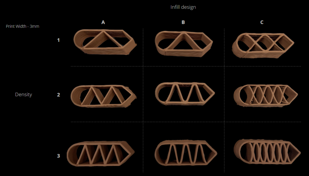
We created a catalogue of 16 simple printing geometries described by four infill types, four infill densities, and 15 discrete coordinates within each part.
The parts featured straight edges of varying lengths, curved edges, and several easily identifiable features, which would be used to orient the physical part to the digital model during scanning for dimension gathering.
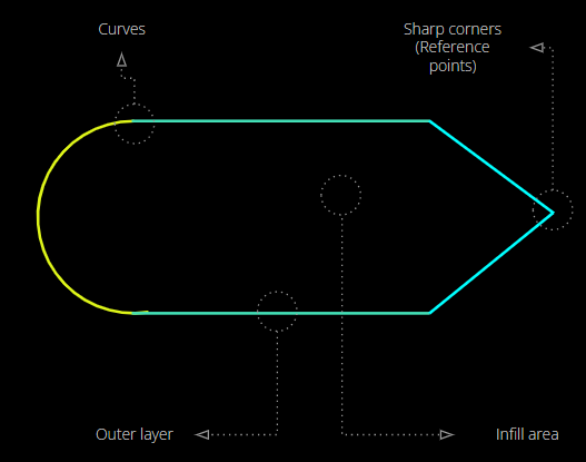
Differences in internal density were achieved by increasing the number of periods in a repeating infill.
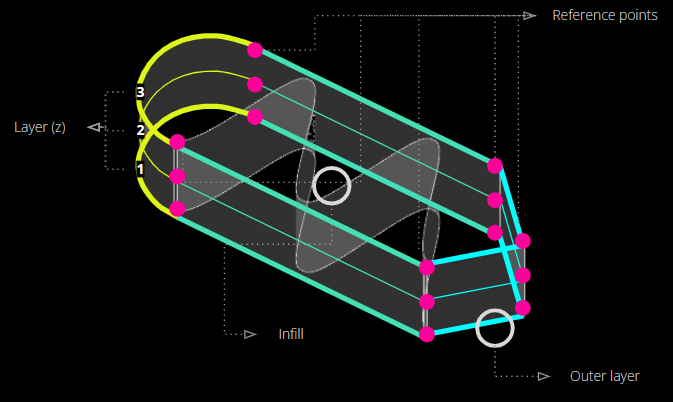
The reference points (in pink, below) are positioned at easily distinguishable points around the perimeter of the geometry so that they can easily be identified on the physical model during scanning. 5 points were placed around the perimeter of each of the bottom, middle, and top layers of the print.
While synthetic data was used to train the model, we also printed and fired each geometry with the intent of testing the same method with real data at a later date. The parts were printed on an Ender printer using a 3mm nozzle (resulting in a printed wall thickness of roughly 4mm immediately after extrusion) and red SIO-2 clay with a moisture content of 25%.
Simulation of Data
To build a synthetic data set, we took the digital model of the parts and applied a deformation to it using Kangaroo in Grasshopper. A mesh was applied to the object, and a contraction was applied to the mesh edges such that they shrank linearly to a percentage of their original length. The base of the part was also anchored to the XY plane to simulate the adhesion of the first extruded layer to the print bed during printing. The resulting simulation provided an approximation of deformation occurring in the X, Y, and Z directions (top to bottom, respectively, in the illustration below) that was reasonably consistent with the drying behaviour of clay based on our experience. The simulated deformation appeared to be similar to the deformation of the physical printed parts based on a visual inspection.
Simulated deformation in the X, Y, and Z directions (top to bottom) of a part with infill type A and density 1. Red indicates high deformation and green indicates low deformation.
Model Characteristics
A regression type ANN was trained on the synthetic data set using backpropagation. A sigmoid function was used as the activation function.
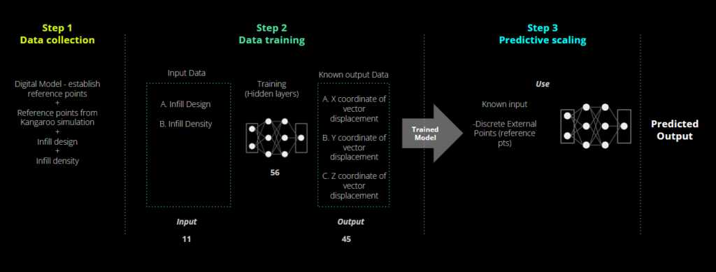
The model was trained to take in characteristics of the part and output a vector indicating the movement of the coordinates from their initial position in the freshly printed part (the designed position) to their final position in the fired part (the deformed position). The network consisted of 11 inputs, 1 hidden layer of 56 neurons, and 45 outputs. The 11 inputs consisted of 4 binary values for the infill type, 4 binary inputs for the infill density, and 3 binary inputs for the extrusion thickness. The outputs represented the X, Y, and Z translation vector for each of the 15 coordinates after shrinkage.
Results
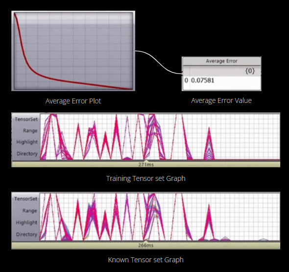
The model was successfully trained to predict the deformation of the discrete coordinate points. A reduction in the network error was observed over time until the average error value fell below 0.075.
The yellow dots indicate the initial position of the coordinate points, while the blue dots indicate the predicted position after firing, which is consistent with the simulated data set.
Next Steps
There are several next steps that we would like to take in order to make use of this work.
- Train and verify the model on a real dataset: Once fired, we intend to scan the parts that we printed in order to construct a real data set with which to train the model.
- Determine the accuracy of the Kangaroo simulation. In creating the synthetic data set we became interested in determining whether the approach of modeling shrinkage in Kangaroo could be used to predict shrinkage accurately. We would like to compare this method to real shrinkage, and also to the predictive results of the ANN to see if one method or the other is more accurate.
- Apply the method to more complex shapes: We simplified the geometries for the purpose of this seminar, but would be interested in applying the method to more complex parts from our Studio, while keeping in mind the concept of simplifying the inputs to reduce computational complexity.
- Apply the method in reverse: As opposed to outputting the points after deformation from shrinkage, we would like to use the model to determine how parts might be scaled before printing so that it shrinks into the desired shape.
