
Introduction to Programming and Physical Computing Seminar
Faculty: Daniel Mateos, Adai Suriñach, Antoine Jaunard
Group Members: Amalia Anna Korgiala, Camilo Hernán Contreras
Concept
The project aims to design a sensor that can work with light or sound sensors, inspired by a library luminaire. The sensor can be placed in various areas and scales, such as indoor activities, museum exhibitions, or outdoor parks.


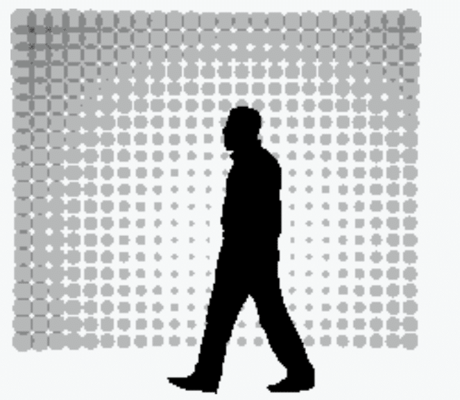
The Light Machine project by Xavier Veilhan at Galerie Lafayette Paris (2016) served as one of our sources of inspiration. The concept of using a screen to convey feelings, emotions, or even a sound in our instance served as our inspiration.
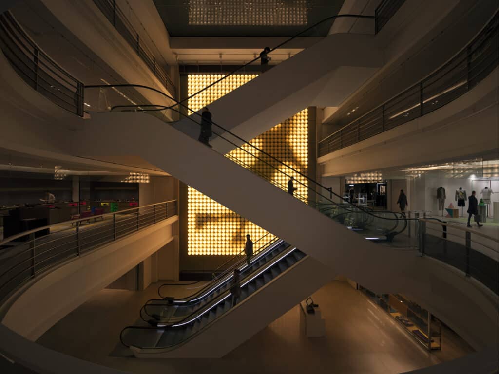
https://haussmann.galerieslafayette.com/en/light-machine-by-xavier-veilhan/
Photo © diane arques © Veilhan / ADAGP, 2016
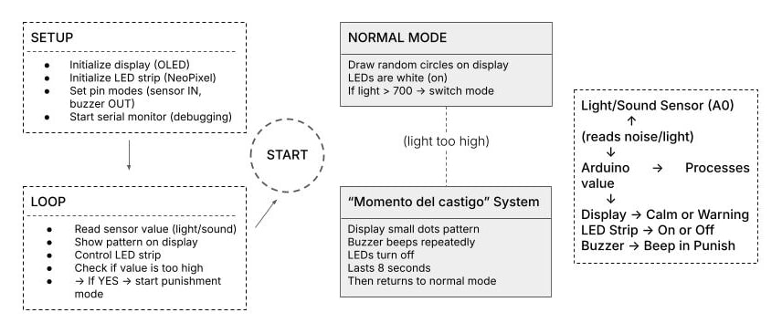
It uses Arduino programming to create four actions: quiet, normal tone, talking tone and “momento del castigo”.
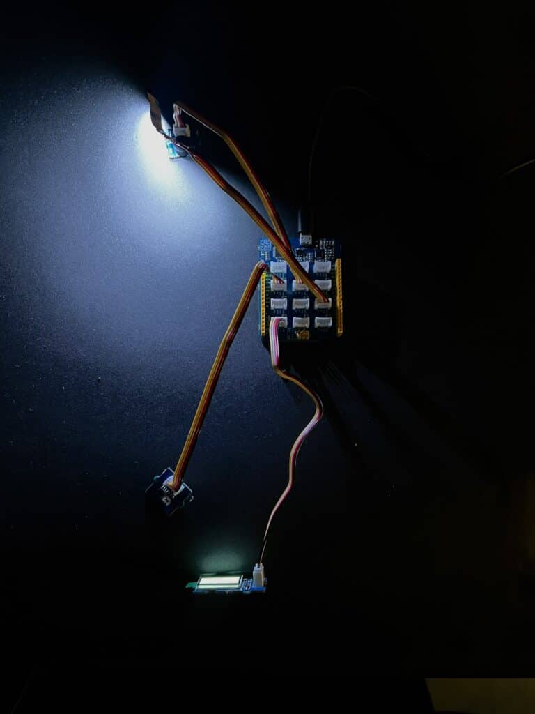
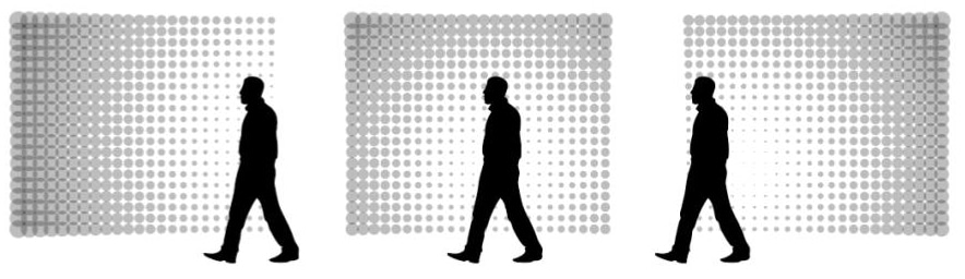
When the library user is quiet, the screen moves normally, allowing readers to read without distraction. When the reader starts to speak, or more light is placed in the lighting sensor, the screen “crashes,” creating distracting shapes and blurry vision. If the library user continues talking, the screen creates circles and fades more, and if the individual doesn’t stop, or full light is placed in the lighting sensor, the screen closes and the lights close by making a small 8-second sound, preventing the reader from staying in the library.
Schematic
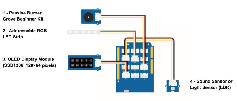
Our system is called “El momento del castigo” and it consists a sensor- input (like the light or sound sensor) and a display (OLED screen), a LED strip and a buzzer as an output.
BOM (Bills of Materials)
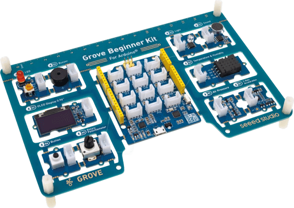
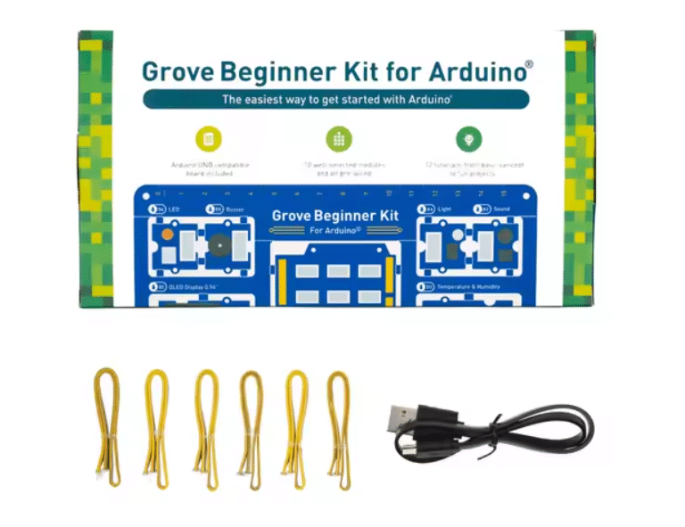
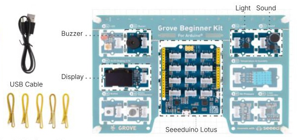
Our BOM (Bill of Materials) includes the Grove Beginner Kit for Arduino, from which we will use selected components. Specifically, we will use the Seeeduino Lotus as the main microcontroller board, the USB cable, and five Grove connection cables.
Price: 25.40€
Source: Product Code: SS-110061162
From the kit’s modules, we will use the OLED Display (0.96”), the Sound Sensor or the Light Sensor, and the Buzzer. These components will be connected to the Seeeduino Lotus to build our custom circuit. In addition, we will include a NeoPixel LED strip consisting of 5 pieces to provide visual feedback and enhance the functionality of the system.

Price: 9.99€
Product Code: B1573RGB
BOM (Bills of Materials)
First, we wrote the code using the Adafruit_GFX, Adafruit_SSD1306, and Adafruit_NeoPixel libraries, which helped us configure and control the desired outputs. Camilo was responsible for developing the code for the OLED Display and creating the sequence for “El momento del castigo”, a concept he had been curious about throughout the week. Amalia was in charge for programming the LED strip, sensor and buzzer, as well as merging both codes, her own and Camilo’s, into a single, integrated program.

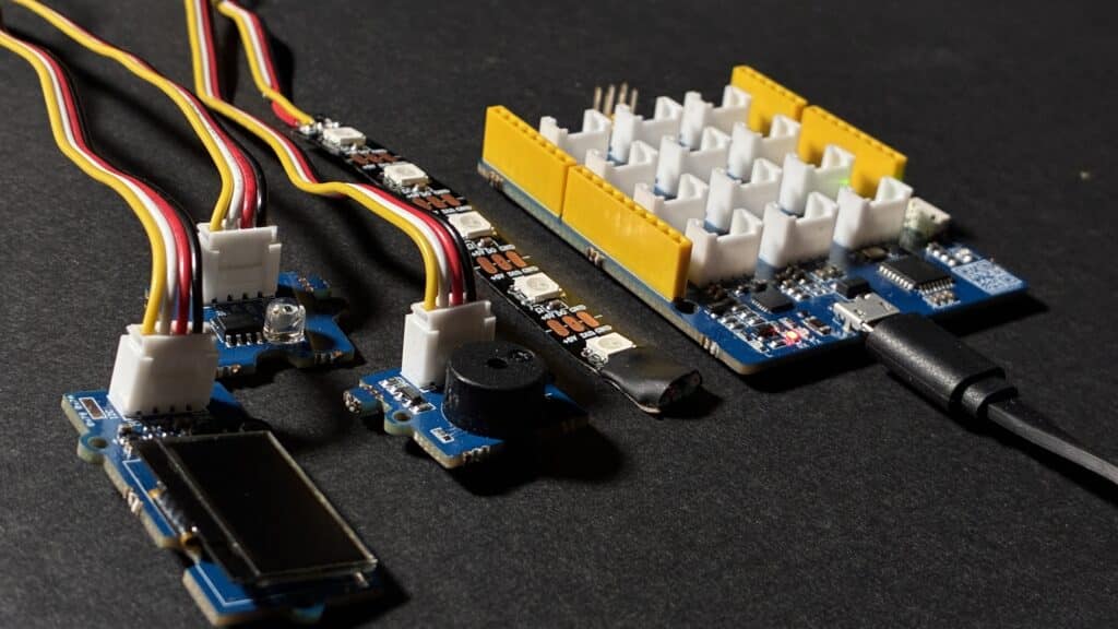
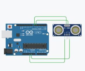
This image shows the components used in our programming setup. The OLED Display is connected to the I2C port, the Sound or Light Sensor is connected to A0, the Buzzer is connected to D7, and the LED strip is connected to D2.
Since our light and sound sensors function in the same way, we decided to experiment with different options based on the location. For instance, due to the noise during the classes, we decided to include the light sensor in the presentation.
As for the display sensor, it’s important to understand the actions we took to get this outcome. We give the individual three chances to comply before the screen completely blurs.
Next Step
As the next step, we wanted to experiment with applying this concept to other contexts — not just as a luminaire, but also in settings such as exhibitions or outdoor spaces. For this reason, we began working with Processing and Arduino, allowing the entire screen to become an active part of our project’s interaction and visual expression.
Programming Code: Processing + Arduino
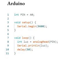
The Arduino board reads real-time data from a proximity sensor connected to an analog input (A0) and through serial communication, Arduino sends this data to Processing for visualization.
Processing receives the sensor values and remaps them using the map() function to control visual parameters such as size, position, or movement.
Arduino and Processing work together as an interactive system: Arduino senses the physical world, and Processing interprets that data to animate a digital response.


range.

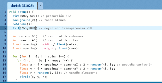
Code 5: Finally, this section maps the light sensor input from Arduino to dynamically modulate the growth rate and maximum radius of each circle in the grid, producing an organic oscillation responsive to ambient light intensity.
