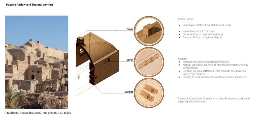
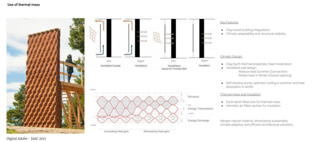
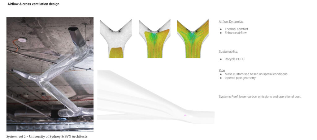
Ventilation is a broad and complex field of study that is linked to heat, humidity, air density and geometry. As this project took place over a six week period we narrowed our focus to a small section of this field of study. The main concepts being intake typology, internal pipe length, and cross ventilation opportunities. The reason for this is that these factors can be easily tested and can be implemented into a digital toolkit for the development of the large scale print taking place in 2025.
With this in mind our hypothesis is as follows:
What combination of passive ventilation strategies can be used within 3D printed earth wall construction to provide optimal thermal comfort?
State of the art
Project plan

Test chamber
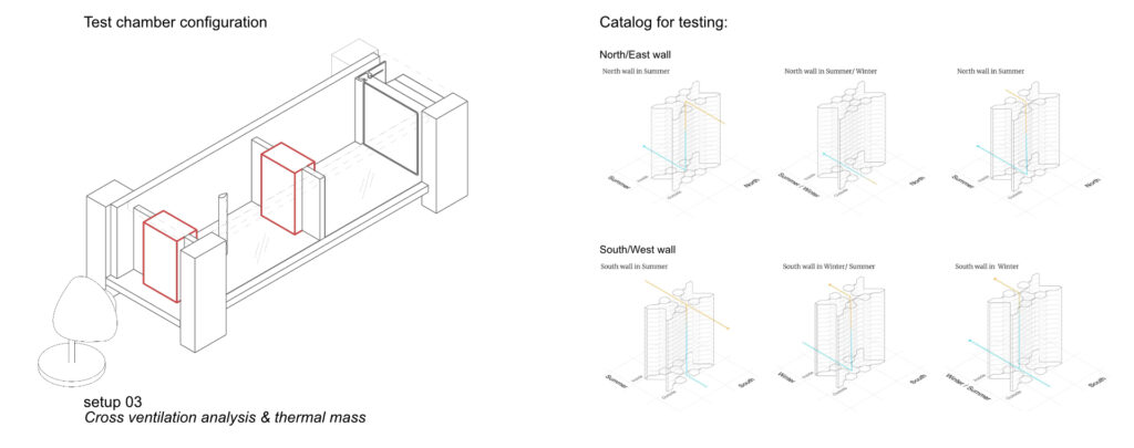
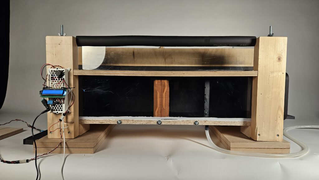
The test chamber is designed in such a way that it can be configured to run different airflow analysis and ventilation tests on many geometries very quickly.
An added element of control was achieved by use of an Arduino that operated the fan speed and calculated the total air moved out of the test chamber by multiplying ‘volumetric area’ against ‘elapsed time/1000’. For cross ventilation and thermal mass analysis 2 temperature sensors were added to take the ambient temperature of the room and temperature of the wall once heat has been applied.

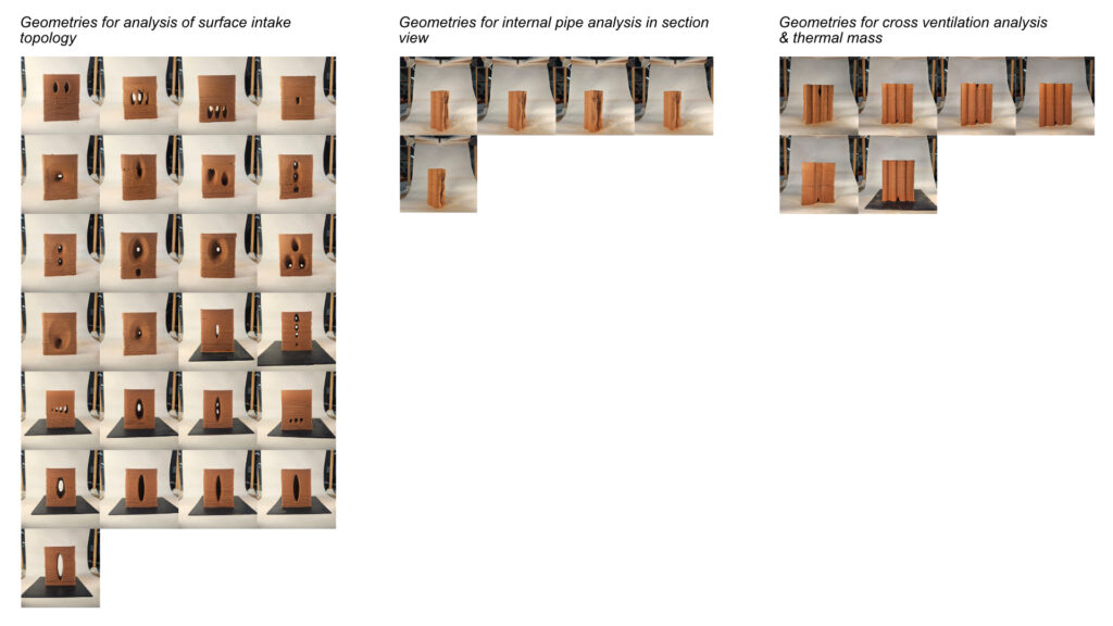
Surface intake topology Catalogue
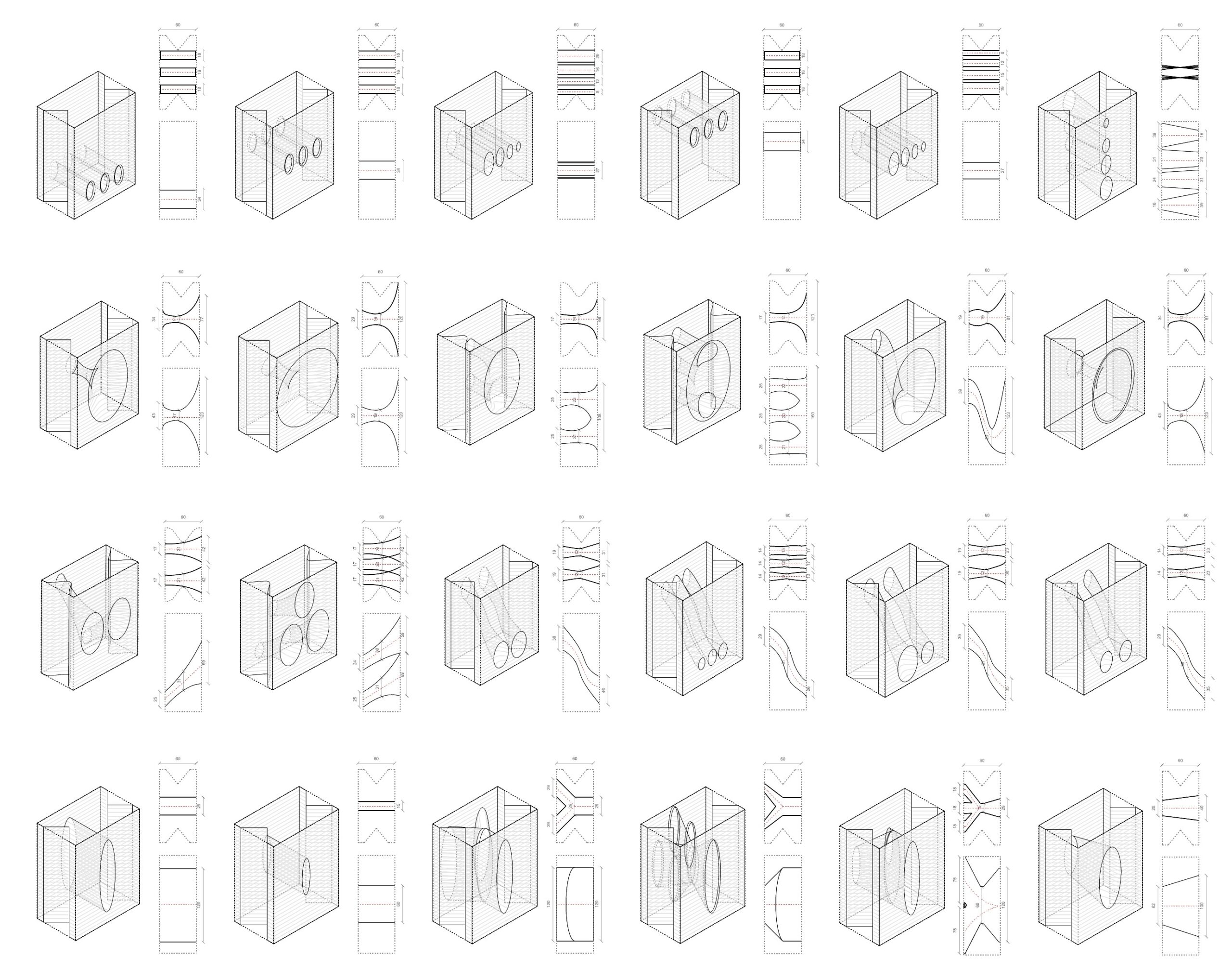
Analysis of surface intake typology
The outcomes from airflow dissipation experiments using different surface intake topologies. The design with a tapered hole showed the fastest dissipation due to its ability to streamline airflow. Another configuration, with evenly distributed intakes, achieved the overall fastest dissipation, providing balanced and efficient airflow dynamics. In contrast, the design with a single large intake and sharp contraction demonstrated the slowest dissipation, as the concentrated flow encountered greater resistance. The experimentation results visually confirm the variations in airflow behavior across the tested configurations.

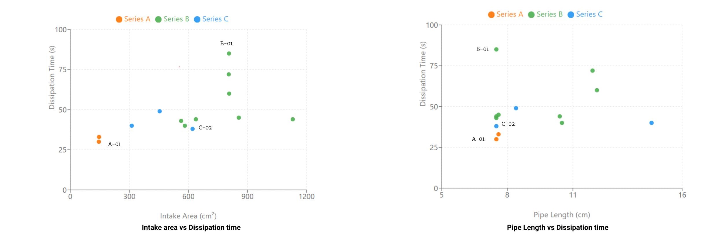
This slide analyzes the relationship between intake area, pipe length, and dissipation time for various surface intake topologies, categorized into three series. The scatter plot on the left shows that smaller intake areas result in faster dissipation, while larger areas tend to prolong dissipation. The chart on the right highlights the impact of pipe length, where shorter pipes generally allow quicker dissipation times, and longer pipes exhibit increased resistance, resulting in slower dissipation.
These findings demonstrate how intake size and pipe length influence airflow dynamics and energy dissipation efficiency.
Ventilation toolkit:

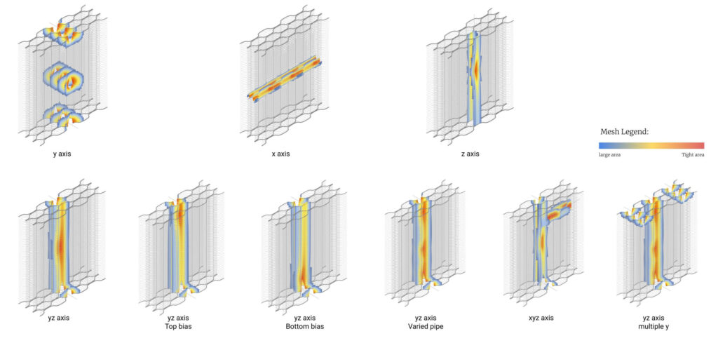
Mesh pipe visualization against CFD analysis:

Correlations can be seen observed between the locations of tight area openings in the mesh analysis and moments of high pressure in the CFD analysis.
With this in mind, we can propose that if the wall is required to hold the are in the walls for a short amount of time to use a smaller diameter tapered pipe design, where as if the wall required the air to move more slowly through the wall there should be a larger internal pipe that can create moments of turbulence or trap air in pockets more easily.
Internal pipe analysis
CFD against section tests
Prototype
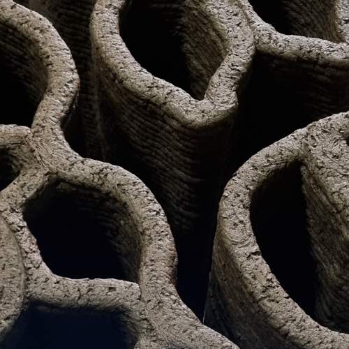
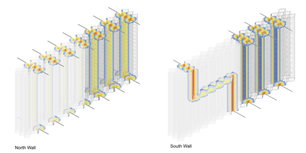
Ventilation proposal


Further Steps
Testing cross ventilation strategies with the application of heat to simulate summer and winter, or day and night scenarios was the next phase of this project. The test chamber would need to be reconfigured to support 2 test geometries along with thermal sensors to read the ambient room temperature and the wall temperature (this was all constructed and completed). For this test we would observe the time it would take for smoke to dissipate from the enclosed volume. Then we would run the same test again with the addition of a heat lamp to observe if the application of heat would produce different results. This test would have been a given us insight into how a cross ventilation system performs against changes in air buoyancy.
