Ingredients
Climate
Reykjavík’s climate shapes the entire project. The site is exposed to strong, multi-directional winds reaching 27 m/s, with a prevailing direction around 135°. Daylight conditions are equally extreme, shifting from long summer days to very short winter ones. The system therefore needs to adapt, protect, and still create comfortable public spaces.
Form
Our formal strategy draws from both natural formations and vernacular architecture. Iceland’s basalt columns organize themselves into efficient, stable hexagonal patterns, while traditional turf houses demonstrate how pitched roofs and thick, layered walls buffer cold air and retain heat. Together, these references show how architecture can work with the climate rather than resist it.
Function
For the cultural hub, we looked to Cecuco by Noa as a key precedent. Their use of a triangular module across scales and their clustered program distribution informed our approach. Research on space‑per-user requirements then guided the indicative proportions of public, semi‑private, and support areas.
Typology
The cluster typology offers a compact footprint and flexible block orientation, making it well‑suited to windy environments.
Sites
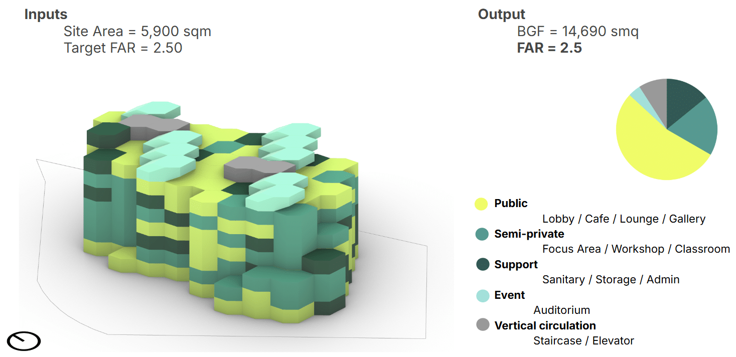
Site 01 – Old Harbour, Reykjavík
The first site is located in the Old Harbour area of Reykjavík, a dense and highly active waterfront zone directly connected to the city center. The plot has a relatively compact size of approximately 5,900 m² and is embedded within a complex urban fabric characterized by mixed mobility systems.
Its proximity to the shoreline, cruise terminal, and promenade makes the site highly visible and strongly exposed to environmental conditions, particularly wind and seasonal variations in solar exposure.
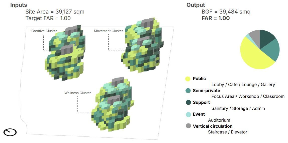
Site 02 – Álftanes, Reykjavík Metropolitan Area
The second site is located in Álftanes, a more peripheral and low-density area within the greater Reykjavík region.
Compared to the Old Harbour, this site is significantly larger, with an area of approximately 39,000 m², and is embedded within a suburban and landscape-dominated context.
The site’s open condition results in greater exposure to wind, but also offers higher flexibility in terms of building orientation, massing strategies, and spatial distribution.
Sites Analysis
Topological Map
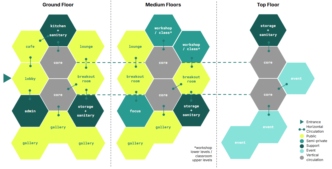
The topological map formed the first step of the project. It guided our early decisions, but it also evolved as we learned more about the needs of a cultural hub and the behavior of the stochastic aggregation system. The final proposal reflects this evolution, and introduces variation through different building levels.
- The ground floor hosts public and support spaces.
- The middle floors combine semi‑private areas for classrooms, focus zones, and workshops.
- The top floor is dedicated to event spaces.
The cores anchor the vertical circulation, while the public modules act as both community spaces and horizontal connectors across the building.
Kit of Parts
Form
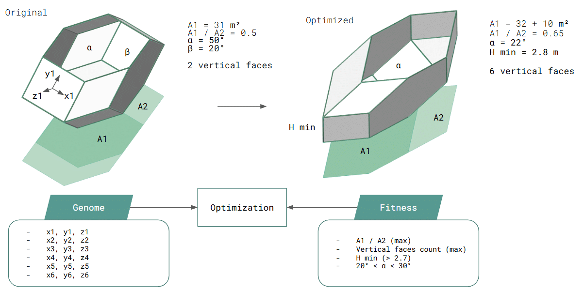
The project is built from a kit of parts that defines its architectural, spatial, and computational logic. The starting point was the quasi‑brick, a twelve‑sided polyhedron of rhomboidal and hexagonal faces. This mix of regularity and irregularity produces dynamic, unpredictable aggregations that simple cubes could never achieve, while the broken geometry helps diffuse wind loads across the envelope.
Because of its geometric complexity, the quasi‑brick required rationalization. We first identified the interior‑angle combination that produced the optimal 22° slope for the auditorium, and limited the use of the quasi‑brick to these spaces. The remaining modules were simplified by extruding the quasi‑brick’s base into prisms, ensuring easier fabrication and more consistent aggregation.
“When stacked, the modules fit together without gaps, a feature essential for adapting to the climate.
Function
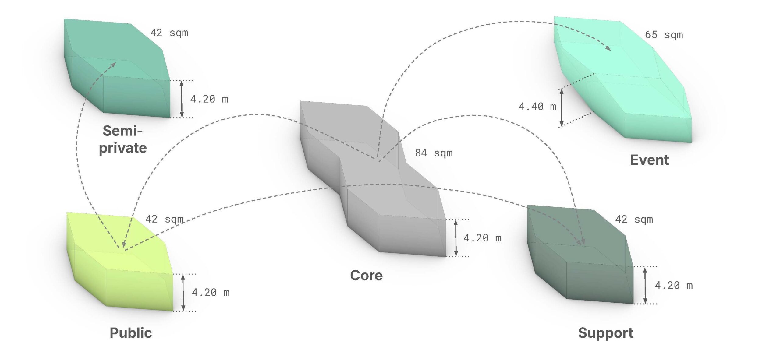
Five main module families are defined, each associated with a specific programmatic role:
- Core, hosting vertical circulation and services;
- Public, accommodating functions such as lobbies, cafés, lounges, and galleries;
- Semi-private, including workshops, classrooms, and focus areas;
- Support, dedicated to sanitary spaces, storage, administration, kitchens, and social support;
- Event, designed for auditoria and large collective spaces.
Aggregation rules were refined in an iterative approach to ensure that every module had access through either the core or a public space. The result is a modular strategy that supports scalability, adaptability, and computational control, forming the backbone of the project’s generative approach.
Module details
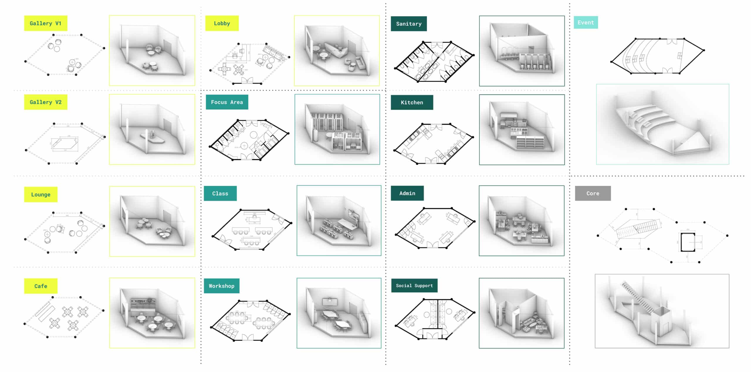
Instead of designing every space individually, the system uses rule‑based modules whose geometry, access points, and internal organization are parametrically controlled.
Each function includes one of three possible furniture configurations, determined by the position of the entrance door along the hexagonal perimeter. As the door shifts, the layout adapts, maintaining clear circulation, functional hierarchy, and spatial coherence.
This logic allows modules to aggregate in multiple ways without compromising usability. Interior elements—walls, doors, furniture—are not manually placed but computed through the aggregation graph, ensuring consistency across the building.
Overall, the module strategy shows how a computational approach can produce spaces that are both controlled and adaptable, linking stochastic aggregation with architectural resolution.
Workflow
Our workflow begins with a topological graph drawn over the site. This graph guides where we place the building cores. We run k‑means clustering on the graph nodes for zoning, then select two nodes for each building. We then compute the shortest path between them along the grid. These paths define the core locations and feed directly into the first aggregation, which generates the ground floor. Through evolutionary optimization, we select the couple of grid points which generates the optimal footprint in terms of wind pedestrian comfort and built area.
The second and third aggregations generate the low‑LOD massing. Next steps are:
- add partitions and openings using WASP smart attributes
- assign interior functions based on type, level and adjacency of each module
- tessellate the façade with hexagonal pattern
- cluster panel types with k‑means
- run structural analysis and optimization.
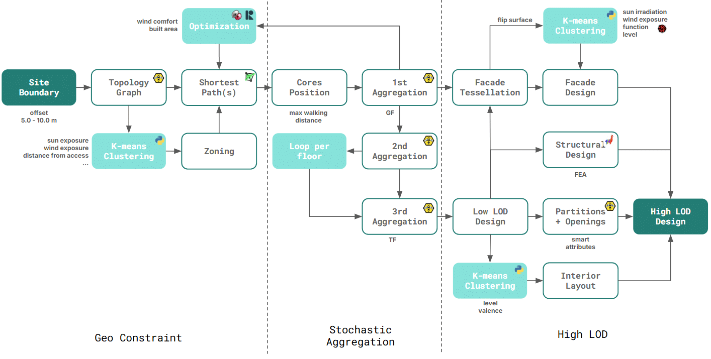
Step-by-Step
The diagram illustrates the entire sequence—from the topological graph to the core locations and through the three aggregation steps. We generate the graph by aggregating scaled modules and orienting them either toward the prevailing wind or along the site’s longest axis. After placing the cores, the building aggregation then grows floor by floor in a controlled loop, and the final step completes the overall volume.
For larger sites, the workflow stays almost the same, with one additional step for zoning. We encode each graph node with environmental data such as sun exposure and wind intensity, and then cluster the nodes with k‑means. Each cluster receives a function based on its characteristics—for example, outdoor areas, creative clusters, movement corridors, or wellness zones. This approach helps us maintain a balance between built and open space and keeps each building within the required constraints: a maximum of three cores and a 30‑meter radius per core.
Environmental Optimization
We integrate environmental optimization early in the process. Using evolutionary search, we refine the building footprint. The endpoints of the shortest paths act as genomes, and the fitness function minimizes areas with wind that is too slow (< 2m/s) or too fast(> 6%). A penalty is assigned for built area below target.
This method produces strong results. About 70% of the site remains within safe wind conditions, even in the worst scenario. At the same time, the thermal comfort variance reduction index also reaches 70%.
Flexibility
The workflow was stress‑tested across multiple site configurations, from the two selected plots in Reykjavík to randomly generated sites. Changes in plot geometry or density requirements did not break the logic; instead, they produced consistent distributions of public, semi‑private, and private spaces, demonstrating the robustness of the approach. Because the topological graph reshapes itself to any boundary, the same workflow adapts seamlessly to compact plots, irregular sites, or multi‑building layouts without rewriting the logic.
Results – Old Harbor, Reykjavik
Results – Alftanes, Reykjavik
Design permutations – Multiple plots
Façade Design
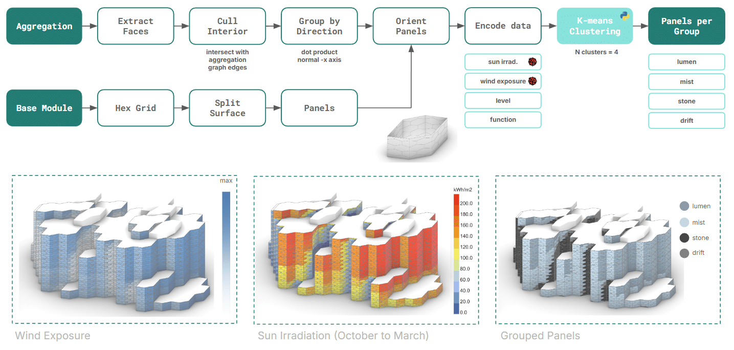
Computational Design
For the façade, we design a hexagonal panel system applied to each prism face. After selecting the façade surfaces, we apply the panels and encode data for each one -level, interior function, solar irradiation, and wind exposure. We cluster the panels with k‑means and create four families:
- Lumen – maximum transparency, south‑facing panels.
- Mist – filtered glass that brings in natural light while increasing privacy.
- Stone – opaque basalt for the darker, wind‑sheltered sides.
- Drift – panels with integrated wind turbines for the wind‑exposed façades.
Materials and Energy
The material palette also draws directly from the site. We use two types of glass, integrated wind turbines, basalt panels, a timber structural system, and a green roof. Each choice responds to the local weather conditions and takes inspiration from the region’s vernacular architecture. The wind turbines cover only about 6% of the estimated energy demand. Yet they act as a symbolic gesture toward Iceland’s commitment to renewable energy. Their integration also requires careful selection to avoid issues with noise and vibration, especially in a public cultural building.

Structural design
The building has hybrid structural system, with wooden CLT slabs and steel pillars. The system is leveraging the concrete core for vertical support and prevention of lateral movement. In the same order steel bracing were add on each of the modules.
The resulting structure has:
- total mass: 16 098 tons
- CLT slabs: 24 144m2
- steel beams: 1124 (total length: 4 886m)
- steel pillars: 1543 (total length: 6 108m)
- steel bracing: 1 488 pieces (total length of 4 293m)
- concrete core pillars: 192(total length of 806m).
- concrete beams: 176 (total length of 755m).
Alpaca 4d performed a linear static analysis. The results revealing a natural frequency of 0.134 Hz and a maximum displacement of 97 mm.
Architectural Design
Next step was increasing the level of detail of interior spaces.
One of the main challenges was finding the position of walls and doors in relation to the Wasp aggregation graph, which describes the spatial organization of the system. Once this logic was established, the furniture layout was generated computationally, ensuring consistency and alignment across all modules.
Plans
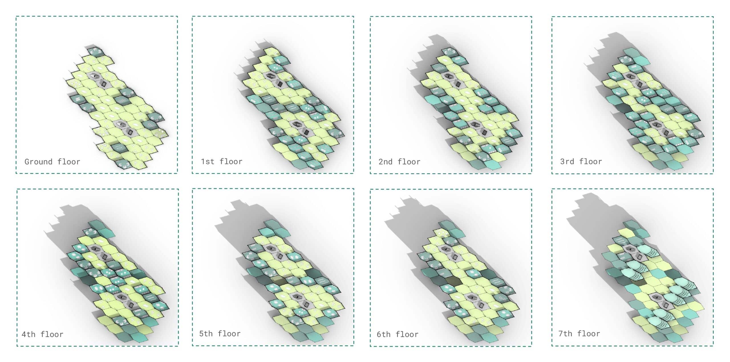
Low LOD floor plans
The topological map guided the aggregation, ensuring that all the modules maintain the assigned level of privacy.
As highlighted by the color coding, the ground floor and the top floor are treated differently compared to the intermediate levels.
Most public functions are located on the ground floor, semi-private spaces occupy the middle floors, while the upper levels host the auditoria and support functions.
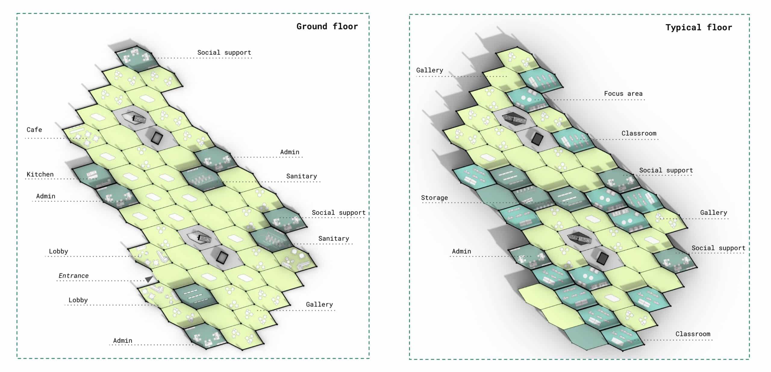
High LOD floor plans
At a higher level of detail, each module is assigned a specific function, based on its privacy level, location, and adjacency to other modules. For example, the lobby occupies one of the outer modules at the ground floor; workshops are placed on lower levels for facilitating material supply; and modules without natural light are designated to sanitary and storage uses.
This strategy improves usability while preserving the underlying modular and generative structure.
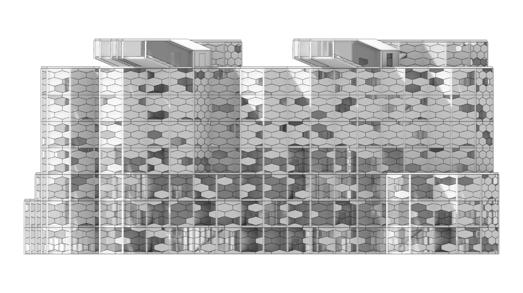
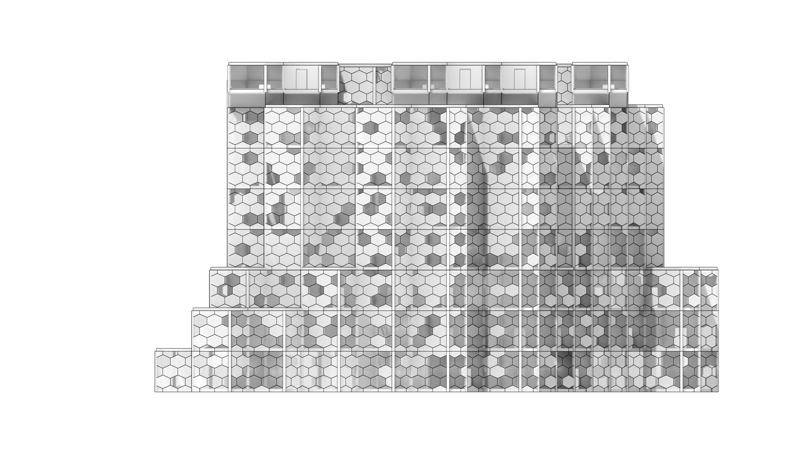
Elevations & Sections
The elevations and section describe the building’s vertical organization.
They clearly illustrate the relationship between structure, floor distribution, and façade articulation.
The envelope is defined by a hexagonal panelization, composed of four distinct material types, selected in response to climatic conditions and orientation.
This system strengthens both the architectural identity of the building and its environmental performance.
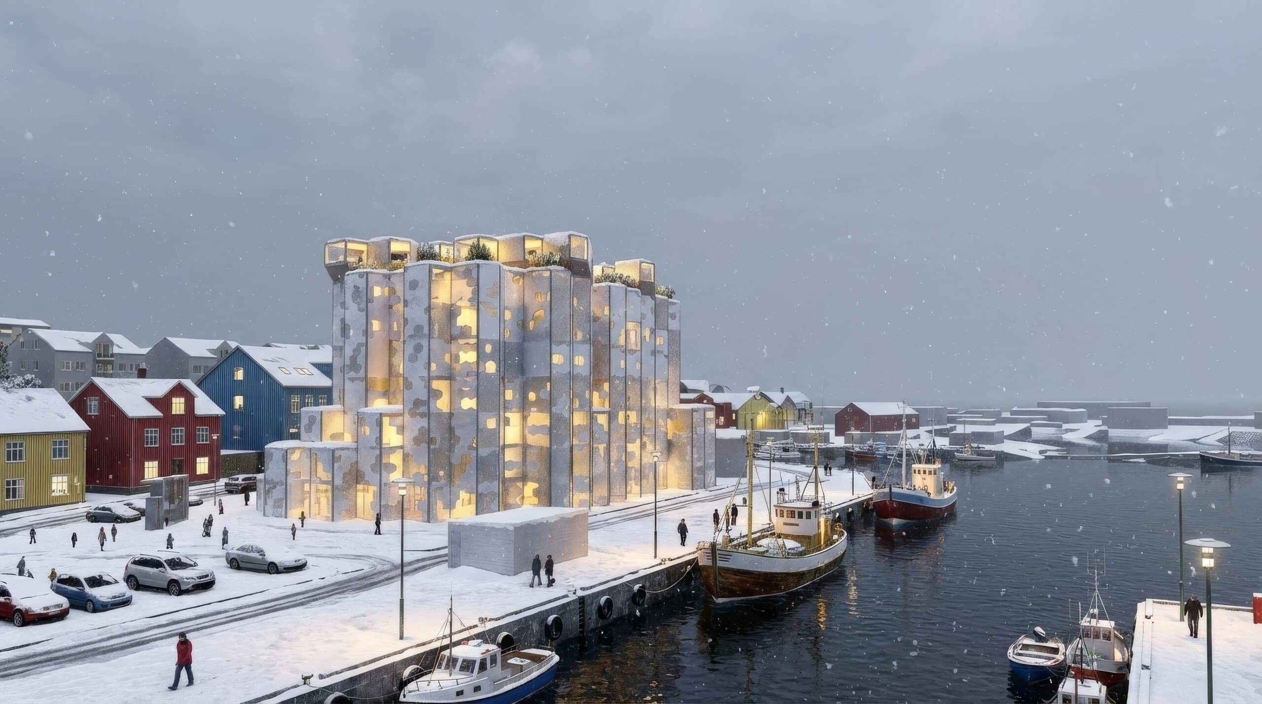
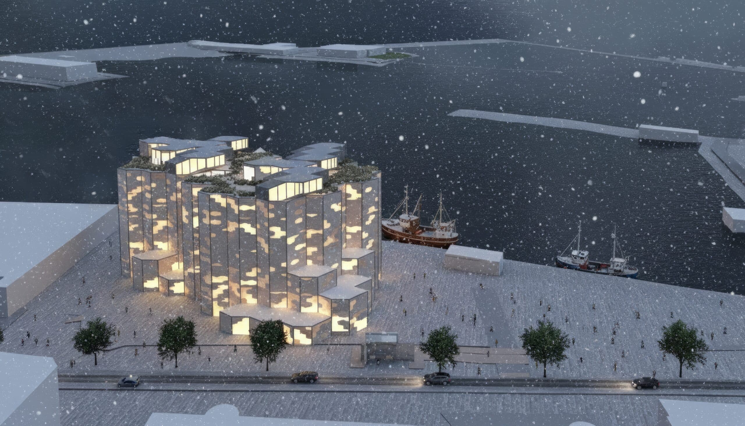
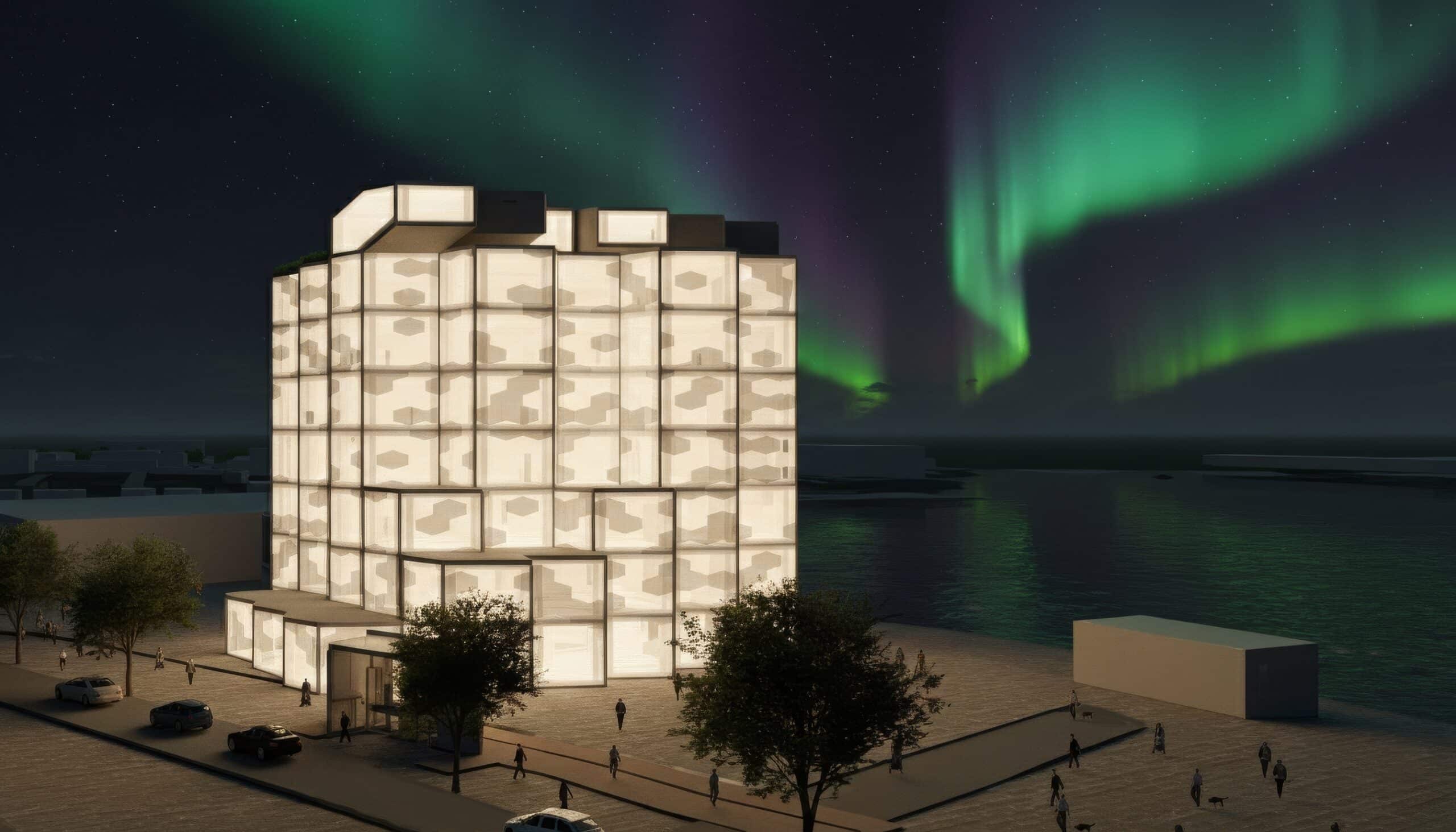
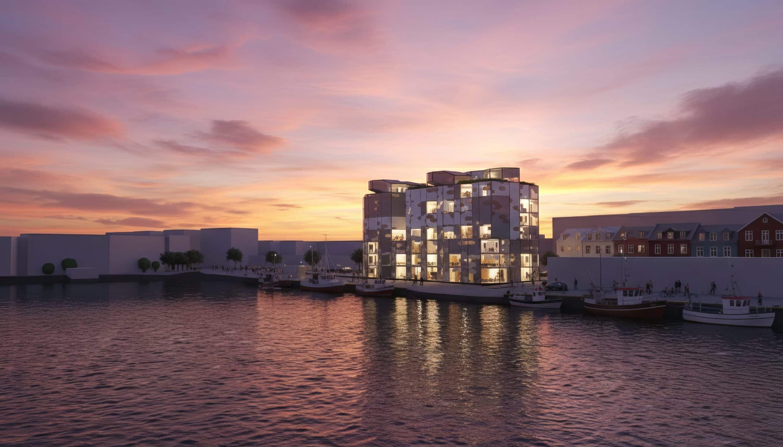
Renders
The renders are used to test and communicate the building’s behavior under extreme climatic conditions, both positive and negative, that can occur in Iceland.
Different scenarios are explored, including storms, snowfall, aurora borealis, winter dark mornings, and the midnight sun.
These visualizations highlight the project’s atmospheric qualities, as well as its resilience and adaptability within the Icelandic context.