Digital fabrication enables designers to explore geometries that go beyond traditional construction constraints. The exercise focuses on translating complex geometries into constructible systems that integrate material behaviour, joinery logic, and mass customisation. Each technique allows experimentation with unique fabrication constraints, informing the evolution of the vertical element design. The outputs serve as material and geometric prototypes, each with potential applications in façades, partitions, sculptural surfaces, modular assemblies, or research samples.
Design Intent & Conceptual Framework
The conceptual foundation is rooted in irregularity. All designs intentionally avoided symmetry, repetition, or uniform modularity. This explores one of digital fabrication’s greatest strengths – the ability to produce non-standard, mass-customised geometries without increasing fabrication time or cost.
The overall investigation examines:
1. How fabrication methods respond to irregular geometry and vice versa?
2. How joints, tolerances, and toolpaths must adapt?
3. How digital logic transforms into material-specific assembly logic?
Laser Cutting
The laser-cutting exploration focused on translating a continuous 3D surface into a modular, interlocking assembly system. Beginning with a form constrained within a 300 × 300 mm frame, the objective was to understand how a complex topography could be deconstructed into flat, fabricable components while still retaining spatial intent.
Geometry Development
- A freeform, mountain-like 3D surface was modeled in Rhino.
- The surface was imported into Grasshopper for panelisation.
- A triangular mesh system was chosen for its structural stability and ability to represent curvature efficiently.
- Between every pair of adjoining triangular panels, a circular connector was introduced, oriented perpendicular to the panel intersections, to act as a joining element.
- Each panel and connector contained precisely positioned interlocking slits, enabling assembly without adhesives or fasteners.
- All components were digitally labelled to streamline identification during assembly.
Fabrication Logic & Nesting Strategy
Material efficiency became a core part of the design logic. By analysing the edge lengths and shared boundaries of the triangular panels:
Panels with identical or similar edge lengths were overlapped strategically during nesting.
This allowed approximately 95% of the triangles to share an edge, drastically optimising material usage.
As a result, the entire geometry could be nested within a single 300 × 300 mm sheet, achieving near-zero waste fabrication.
Final Model

3D Printing
Concept & Strategy
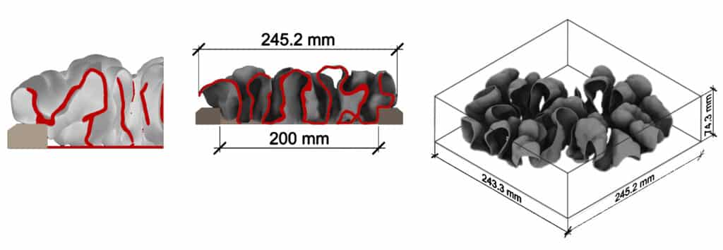
The design for 3D printing exploration was inspired by differential growth, following rules observed in coral reefs and cellular expansion. It shows how natural principles with simple rules repeated over time can generate complex and beautiful geometries, revealing the deep connection between biological logic and architectural form.
The additive process enabled complex forms impossible in subtractive methods, with careful attention to overhangs, wall thickness, and mesh cleaning.
Process and Design
Differential growth causes certain regions of the surface to expand, fold, and overlap, generating local thickness variations and intricate curvature. These geometric characteristics naturally influence printability, often eliminating the need for supports while printing.
The resulting prototype exhibits inherent flexibility, derived from both its material behaviour and its geometric patterning. Differential growth produces a network of slender, branching lines and soft curvature transitions.
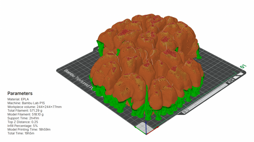
The following parameters were tested with the first prototype: Wall thickness, Surface Modulation, Surface smoothness, Supports density, and Supports requirement.
Further, the multiple folds and arched form of the closed regions helped reduce the overall time required for printing.

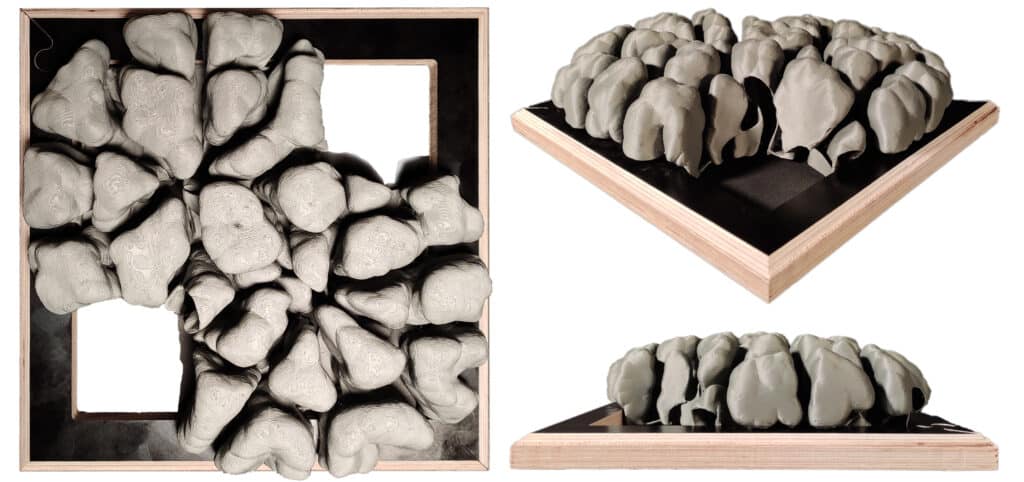
Final Design
Based on inferences from the prototype and to optimise fabrication, the design was calibrated to the characteristics of the FDM workflow. The wall thickness is set to 2 mm, a direct multiple of the 0.4 mm nozzle, ensuring that the machine deposits continuous perimeter lines without generating unnecessary infill or zig-zag motions. This significantly reduces printing time while improving the surface finish and structural coherence.
Fabrication Logic and Parameters
Where the geometry produces self-supporting folds, overhead regions are intentionally left without supports. The Bambu Studio paint tool is used to precisely control support generation:
Red regions → avoid support
Blue regions → allow support

Final Model
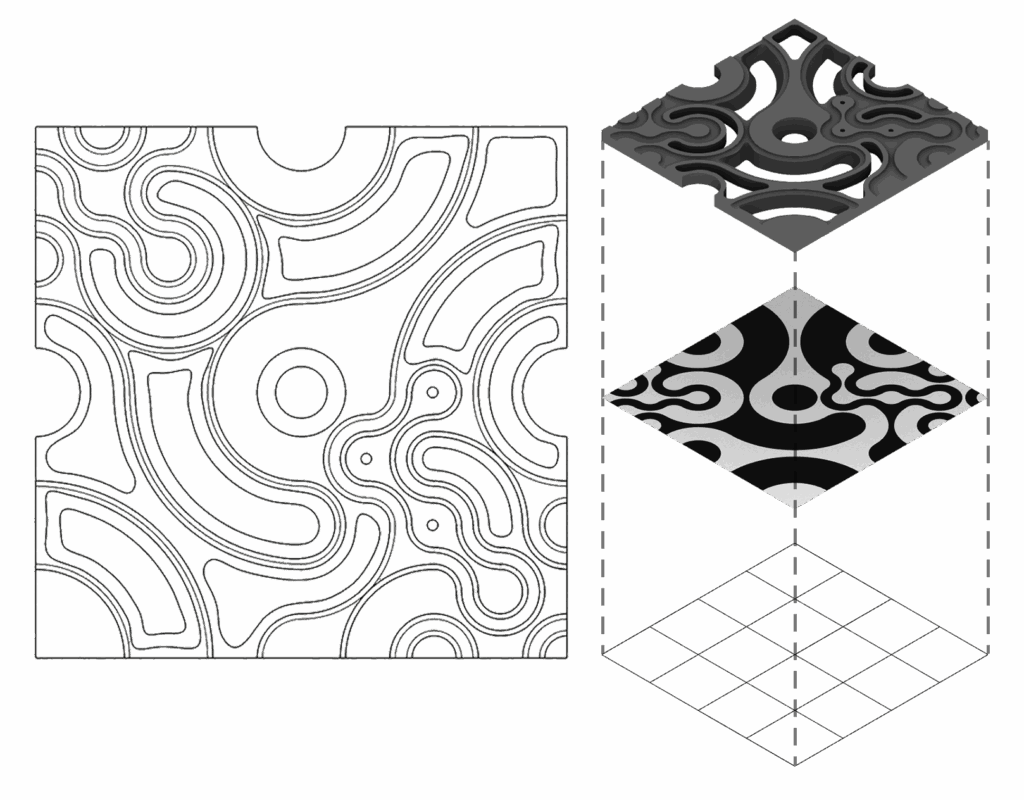
CNC Milling
Concept & Strategy
The design focused on the transformation of a rational 2D grid system into a fluid Truchet-patterned geometry. The pattern is composed of fluid, swirling shapes that create a sense of movement and depth, resembling modern arabesque or parametric design.
The Truchet pattern, composed of curved modular tiles, can expand infinitely, forming continuous and harmonious surfaces through simple repetition. Its round geometry allows endless random variations that always remain visually balanced and multi-scale in nature. When crafted using CNC, its precision and repeatability enhance the fluidity of the pattern, making it ideal for creating intricate, seamless designs across materials like wood or metal with high accuracy and aesthetic depth.

Geometry Development
- Start with a rational square grid
- Introduce curved modular tiles → Truchet logic
- Generate fluid, swirling patterns
- Extrude geometry into 3D tile depth
- Aggregate repeated units into a continuous spatial surface
- Outcome → a surface that reads as parametric, dynamic, and infinitely extendable
Fabrication Prototypes
Plywood was selected as the fabrication material due to its affordability and machinability. However, plywood presents challenges, especially at the edges, due to the alternating grain directions. This required strategic tooling choices to achieve a clean, expressive outcome.
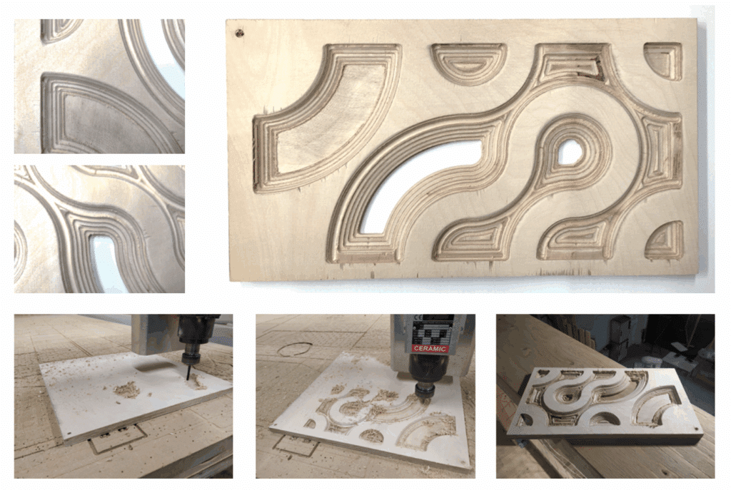
CAM Workflow
To optimise both toolpath quality and fabrication time, multiple operations and tools were combined:
1. Engraving / Drilling (6mm Endmill)
Used to drill registration holes.
Ensured accurate placement and reduced shifting during later passes.
2. Horizontal Roughing (6mm Endmill)
Removed the bulk material from the curved surfaces and recessed areas.
Operation limited to selected internal curves → significantly decreased machining time.
3. Horizontal Finishing (6mm Ball Nose)
Used instead of standard parallel finishing to create a concentric toolpath that follows the geometry’s flow. Produced smoother curvature and reduced machining marks.
Restricted to specific curve domains → increased efficiency.
4. Edge Finishing Pass (6mm Ball Nose)
Because plywood splinters easily, a final profiling/engraving pass using a ball mill ensured a cleaner edge finish and highlighted the pattern’s curvature.

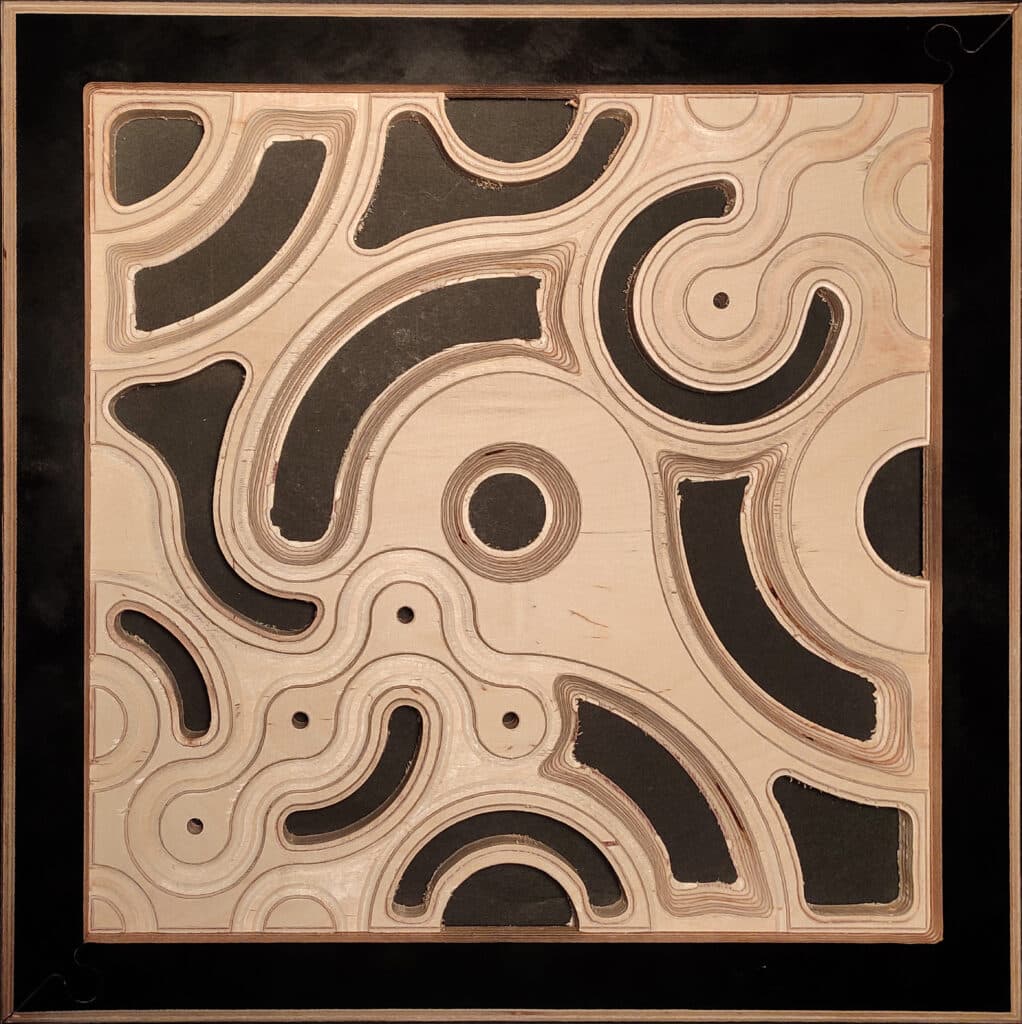
Final Model
Robotic Fabrication
Concept & Strategy
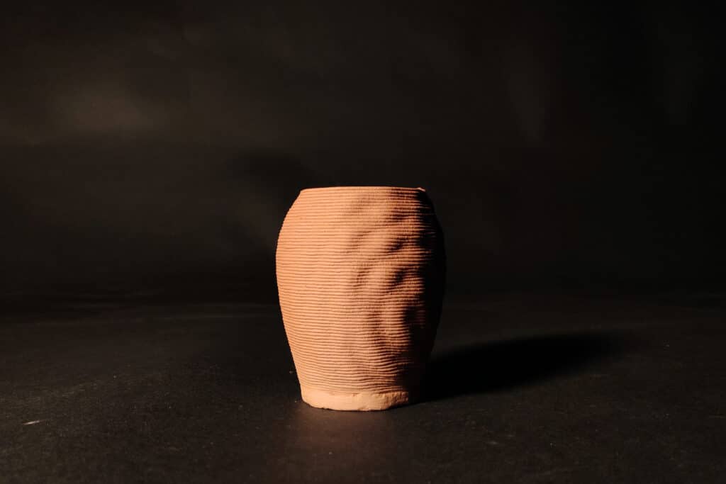
The robotic fabrication experiment focused on exploring material-responsive design through clay extrusion. The intention was to leverage the precision and repeatability of robotic motion while embracing the inherent variability of clay as a soft, deformable medium.
The design a small vessel with subtle surface noise served as a testbed to study how toolpath logic, material pressure, and robotic kinematics influence the final form.
Geometry & Toolpath Development
The vessel geometry was developed with a gently perturbed surface, introducing noise-based deformation to test robotic accuracy in rendering fine surface variation.
ABB Robotics components for Grasshopper were used to generate a continuous, collision-free toolpath.
Toolpath logic consisted of:
1. A zig-zag infill for the base
2. A single-line spiral or contour path for the vertical walls.
3. The surface noise was embedded directly into the path, although the subtle deformation produced minimal visible effect because of material limitations at small scales.
Robotic Setup & Material System
- A 500–600 ml clay cartridge, pneumatically driven, was mounted on the extruder attached to the robot’s end-effector.
- The extruder was fitted with a 4 mm nozzle, calibrated to extrude clay at 2.5–3 bar pressure.
- Layer height was set at 1.5 mm to maintain stability, while line width matched the nozzle diameter at 4 mm.
- The clay’s tactility (compression and spreading after extrusion) became a defining factor influencing print quality and precision.
Challenges & Material Behaviour
The printing of the base layer revealed significant insights into clay behaviour:
- During the zig-zag base path, the extruded clay naturally spread laterally, causing excess material to accumulate around the nozzle.
- This build-up began to stick to freshly printed lines, occasionally lifting or dragging the clay due to its cohesive behaviour.
Final Model