Table of Contents
Abstract
Design
Previous Research : LIGHT [ AIR ]
Tova vs Kibaha
Porosity
Compositional grid for Kibaha prototype
Technical Challenges
Material Recyclability
Foundation & Cast
Overhangs
Edges condition
Mesh grids
Offsets
Approach curves & curve order
Ventilation
Conclusion
Abstract
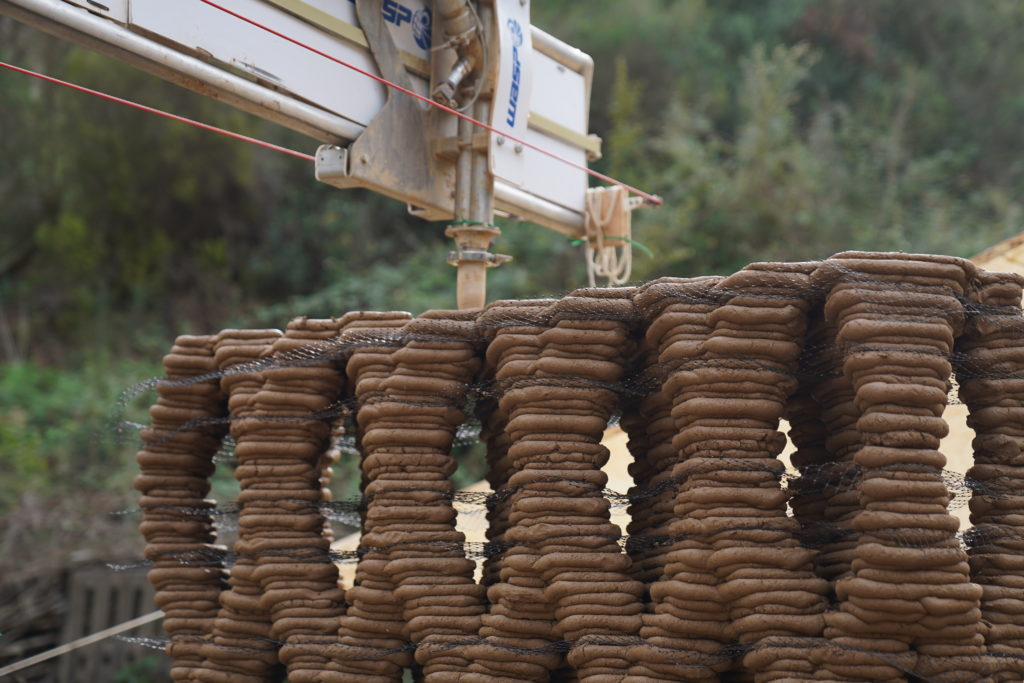
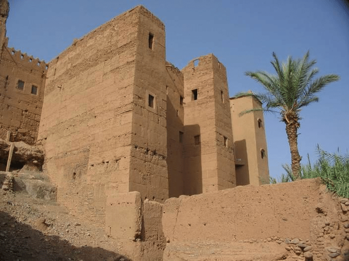
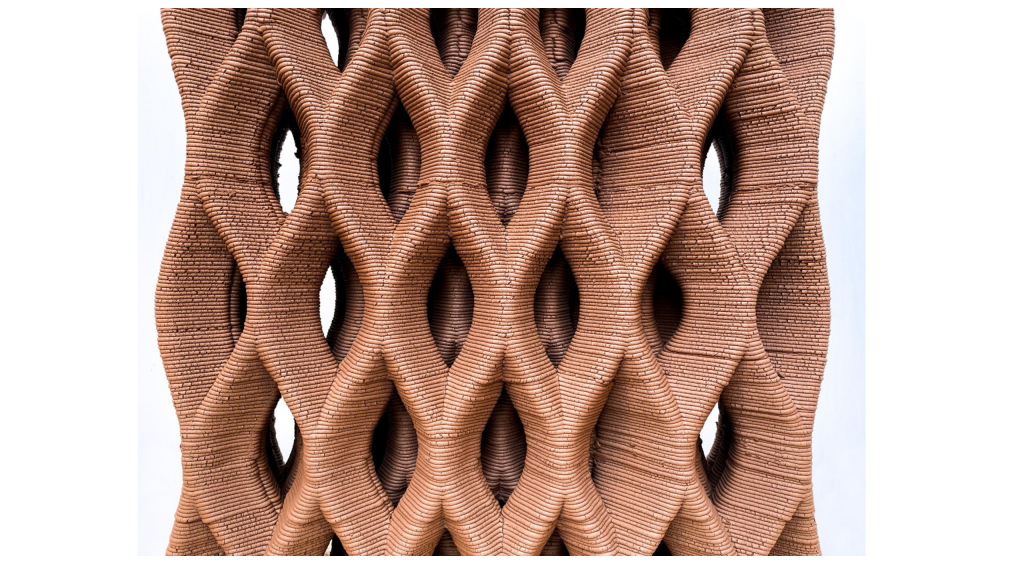
The relatively low mechanical strength of earth means that its use in traditional construction often leads to walls that are both thick and opaque. Windows are normally constructed with the introduction of a different constructive element which can make building processes more complicated and less fluid. As a result, earth walls tend to be blind and earth architecture relatively dark.
One of the strengths of 3d printing, its digital workflow and the consequent flexibility in design, is that we can design a wall by customizing its geometries. Combined with a careful understanding of the tool, the material behavior and its structural properties, one can envision the construction of a wall that contains porosities, and therefore let in a controlled amount of light through its depth, across the space.
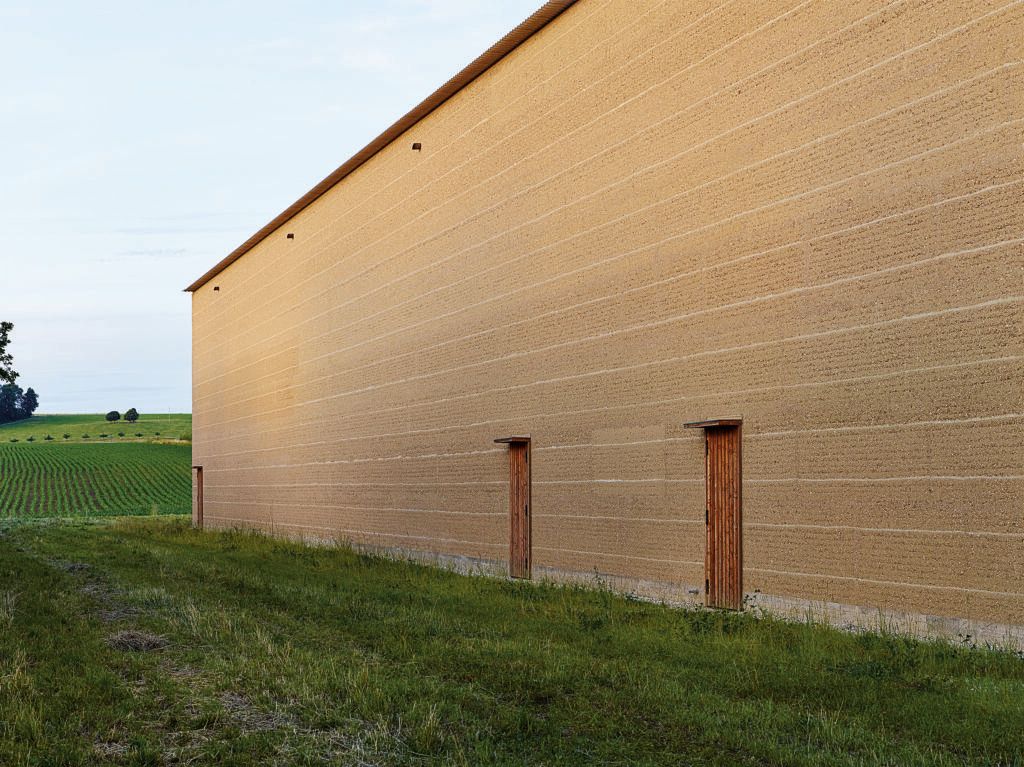
Photo by BenediktRedmann
3dPA’s working methodology rests on what we call performative design, which implies that the morphology of a building element or of a print, emerges as to fulfill a – or several – chosen performance. The performance comes first, it is discussed, tested, designed, engineered, drawn, modeled… and then only, can serve as information in order to define the geometry of the printed elements.
Light was explored as a performative element in order to inform the design of an earthen printed room that lets in as much daylight as possible. Furthermore, daylight will be analyzed in two ways: direct and diffuse. Considering that direct daylight into buildings can be synonymous with unwanted heat gain, we will carefully calibrate our prints and develop bouncing – or reflectionary – strategies to keep it out, while encouraging as much diffuse light as possible in the space.
Design
Previous Research : LIGHT [ AIR ]
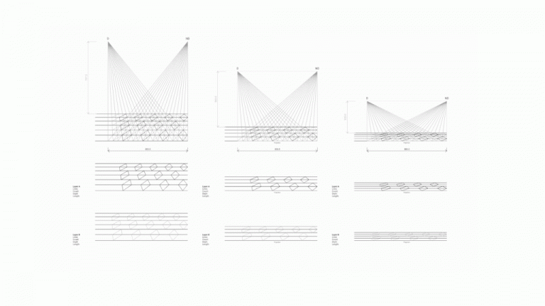
This project builds on the research developed in the “LIGHT [ AIR ]” Project (Luis Buerba | Lynette Masai | Tapiwa Mirirai Manase https://www.iaacblog.com/programs/light-air/ ) They designed a porous wall as an intricate of parallel layers that would allow specific points of view to pass thru using a grid base on points of view.
“The geometry is (…) optimized for light by establishing two explicit points, A and B that represent direct light and diffuse light. These serve as the basis for refining the cross-section geometry, rotation and layer count and spacing, to achieve opening geometries that respond very specifically to light. A consequence of this approach is that the geometry also demonstrates a privacy gradient in addition to letting in light and air”
The prototype of the previous research was working with parallel layers, similar to what was designed for Tova, the full scale prototype of the same year.
Tova vs Kibaha
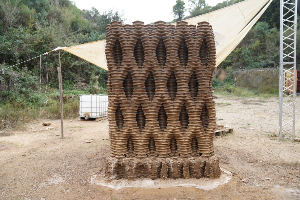
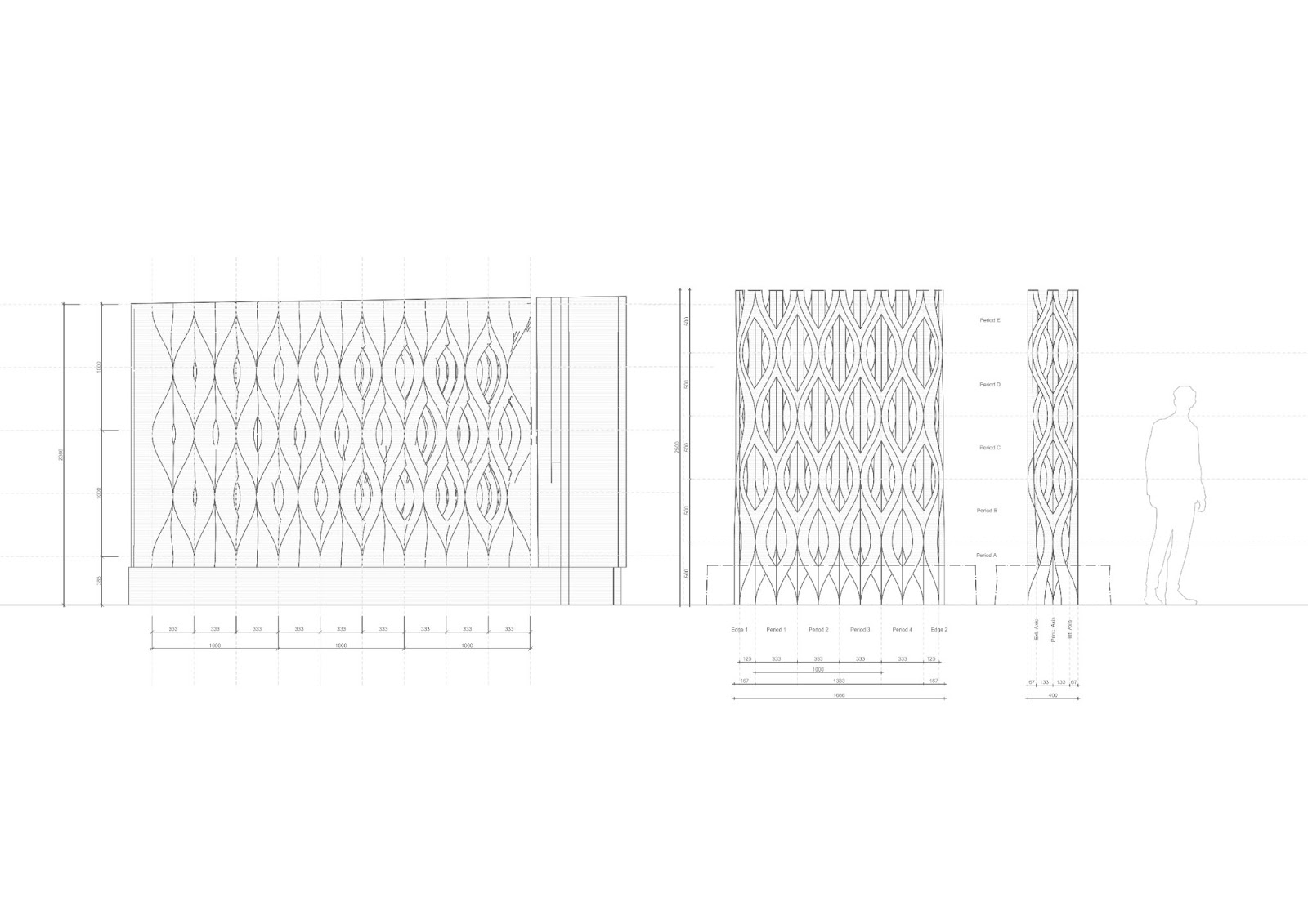
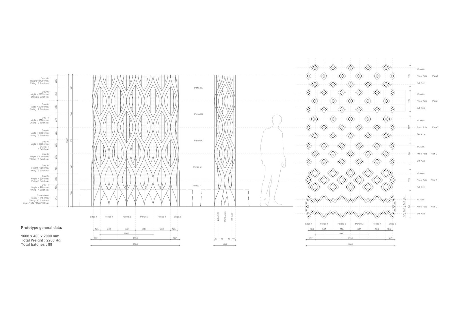
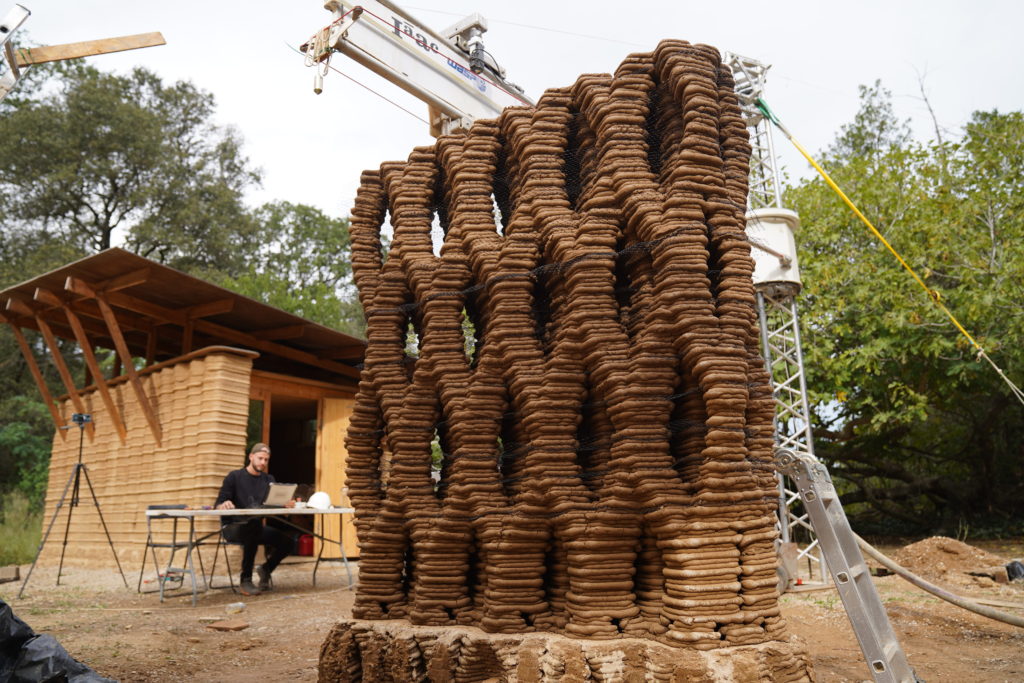
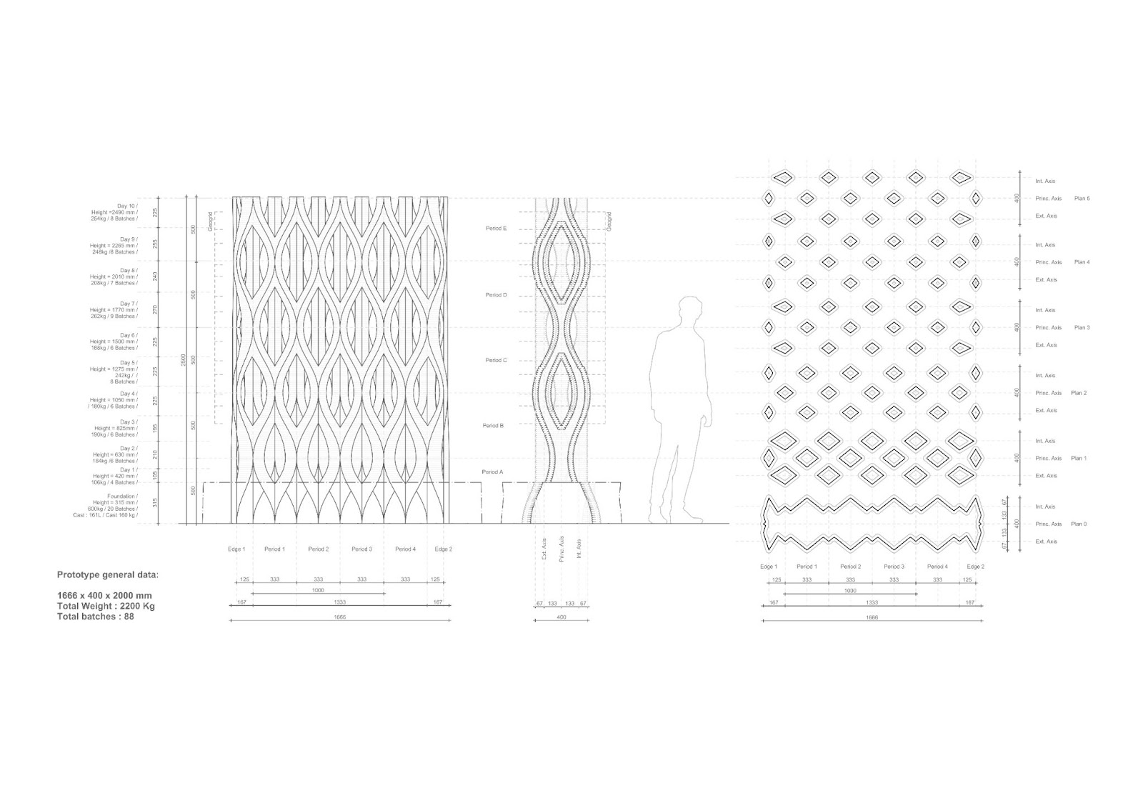
Kibaha was designed to challenge the geometries already present in Tova. The pattern’s dimensions were reused to match the two prototypes’ scales. The pattern is 1m by 1/3m , ensuring some stability and an homogeneous visual system. The Height was also matched to reach 2.5m. The second intend to be the extension of the one, a fragmented, but unified architecture.
Porosity
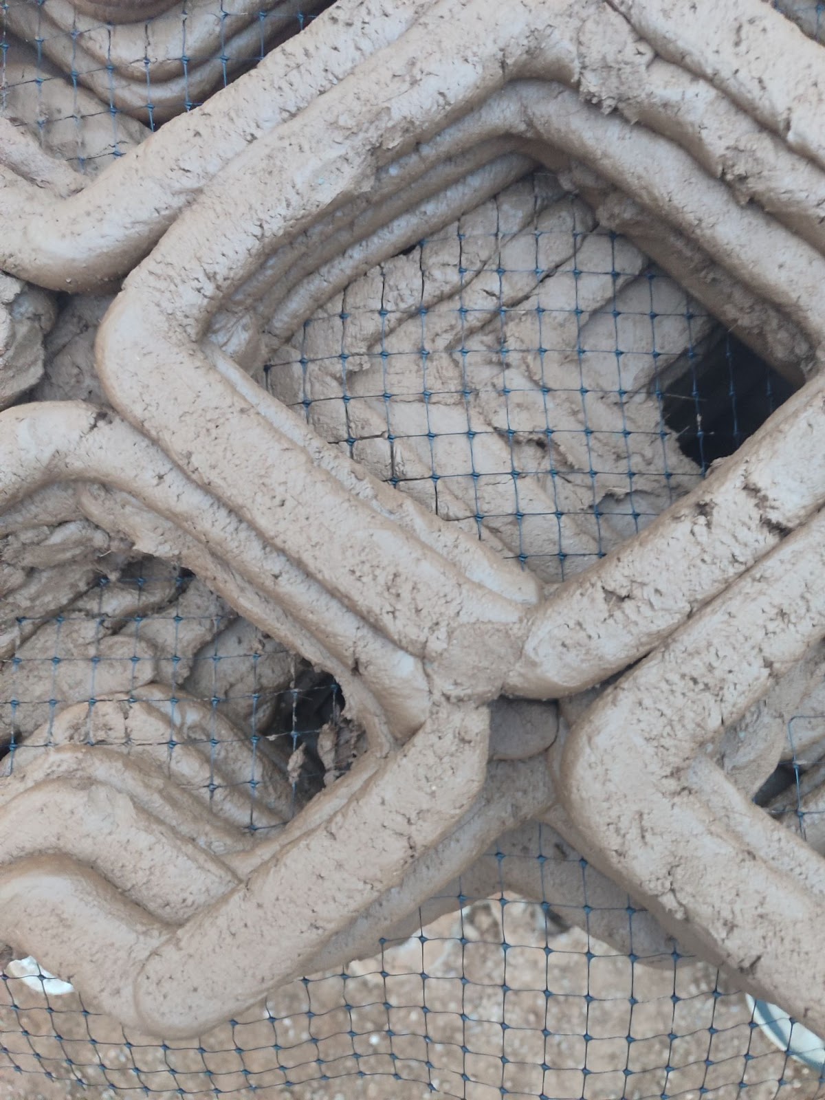
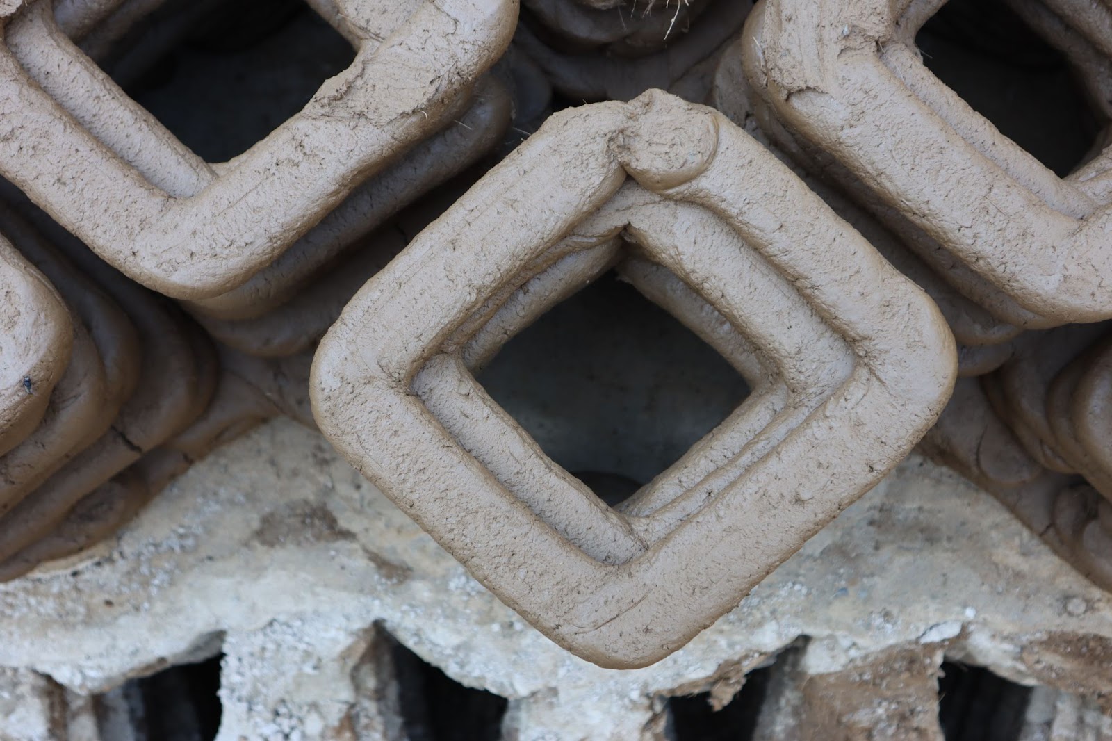
This specific system allows the design of geometries with high levels of porosity. Porosity can be interpreted in various ways, as direct light, indirect light or sight. The first one controls heat, the second light, the third privacy. The prototype here intended to fix the architectural limits of such a geometry, with such a material. Setting up the framework for an architectural design process. A vectorial process has been set-up to measure the amount of direct light passing through. This simplification of a complicated natural concept such as light allows to understand what are the design parameters to be integrated in a geometry.
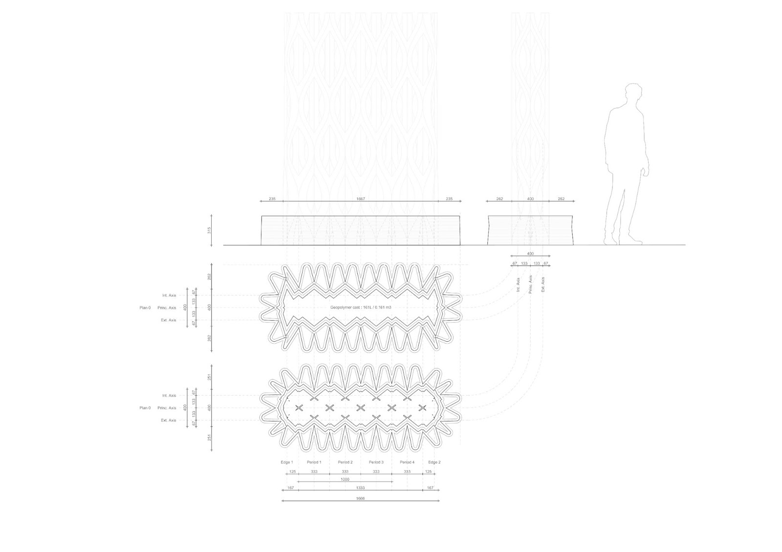
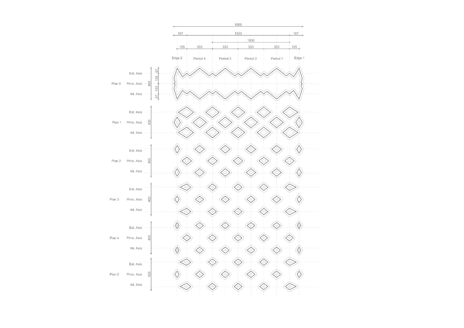
Compositional grid for Kibaha prototype
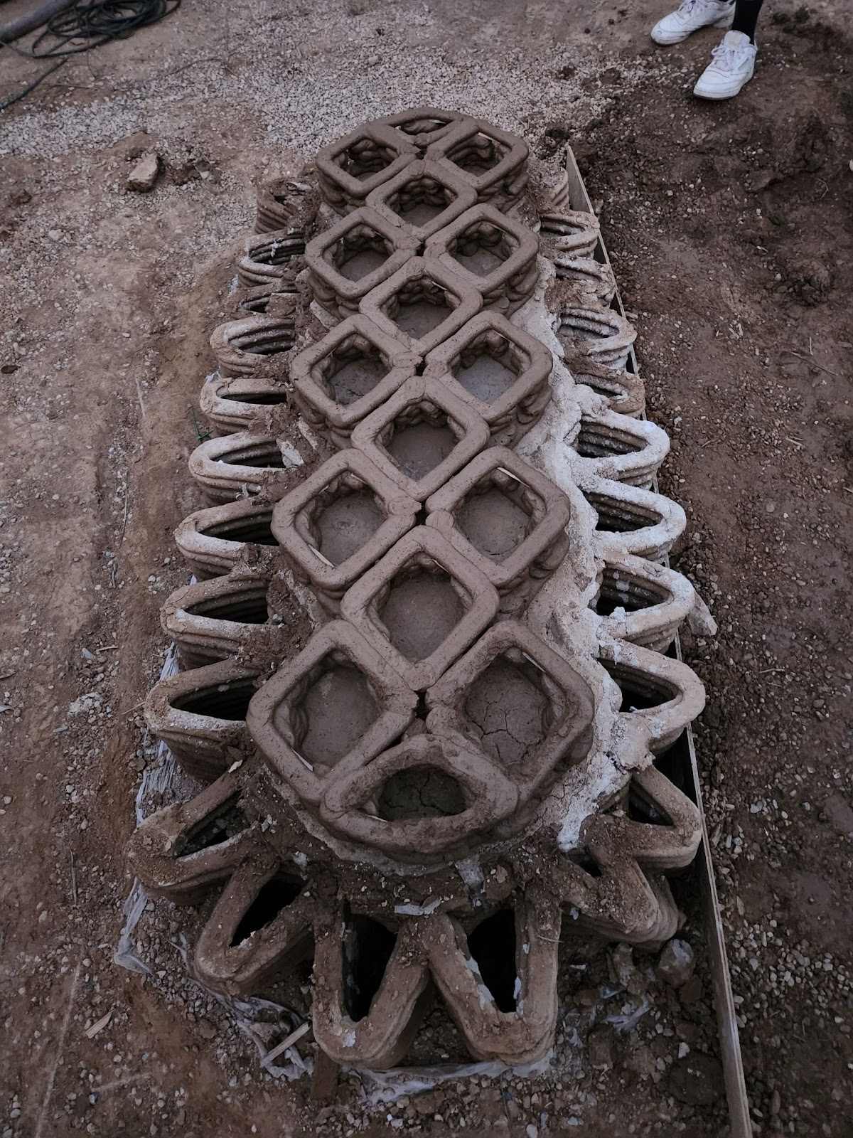
The grid is composed of two distinct levels in a regular grid system. The cell are placed in a chessboard manner, level 0 as the ‘white’ cells and level 1 as the “black” ones.
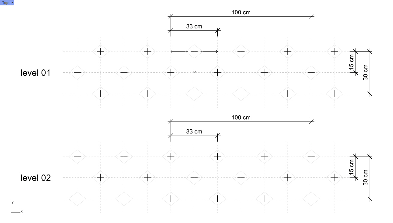
Therefore, we can compose a 3D model by moving those cells at different levels and producing interconnections. According to their situations, cells will connect to either 2 (edges), 3 (corner) or 4 (center) others.
Technical Challenges
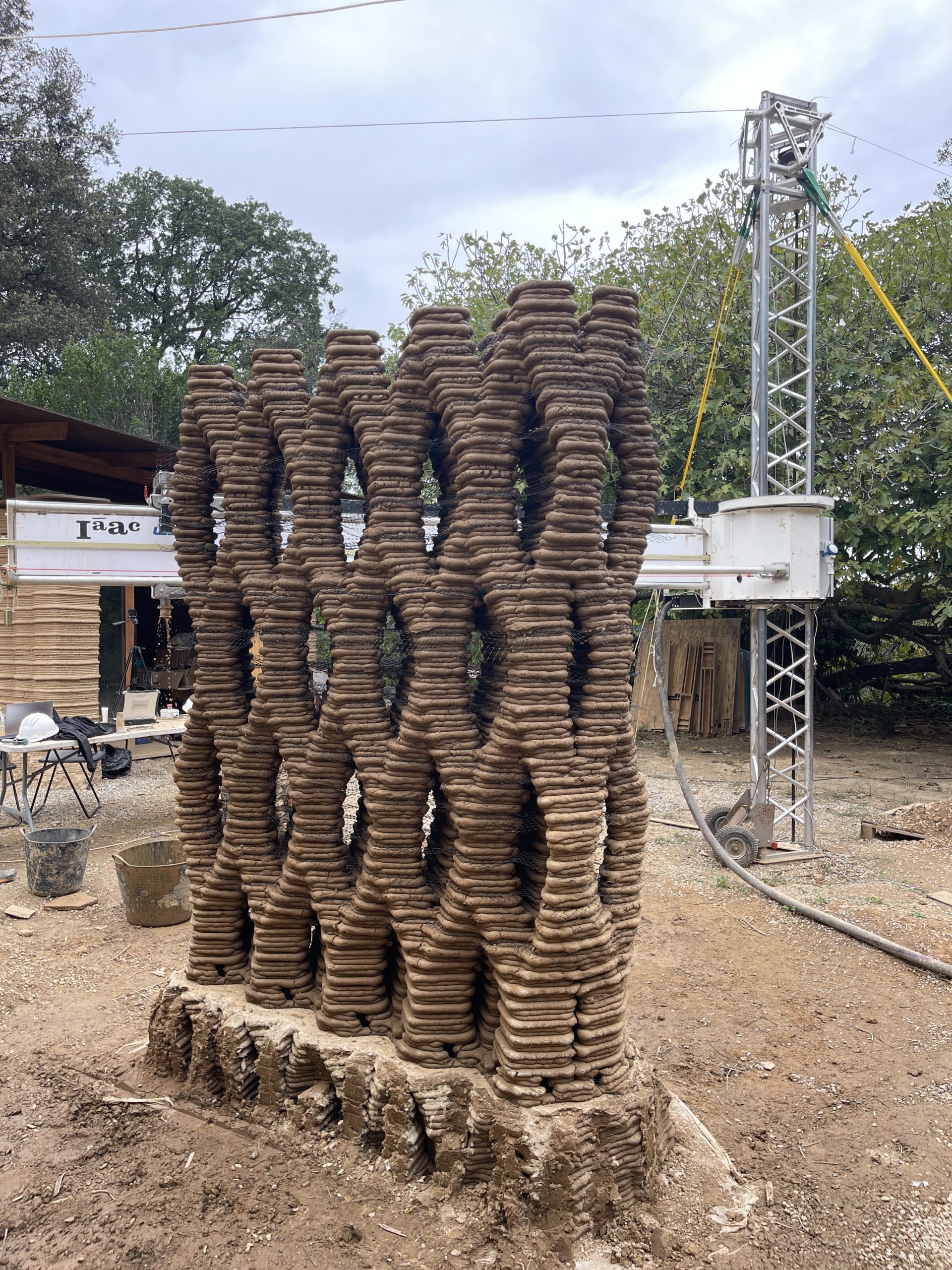
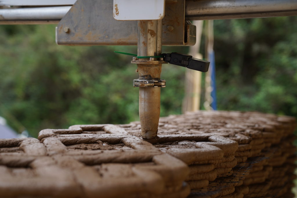
As the prototype was brought to the 1:1 Scale, a number of specific technical issues related to earth 3D printing could be extracted and their challenges solved.
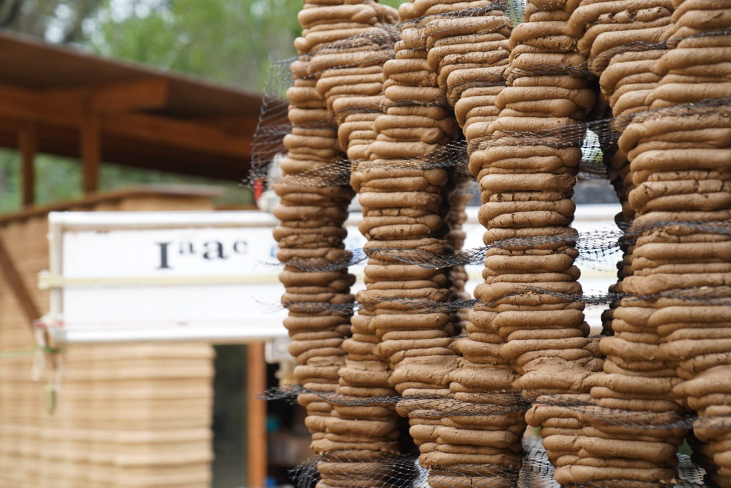
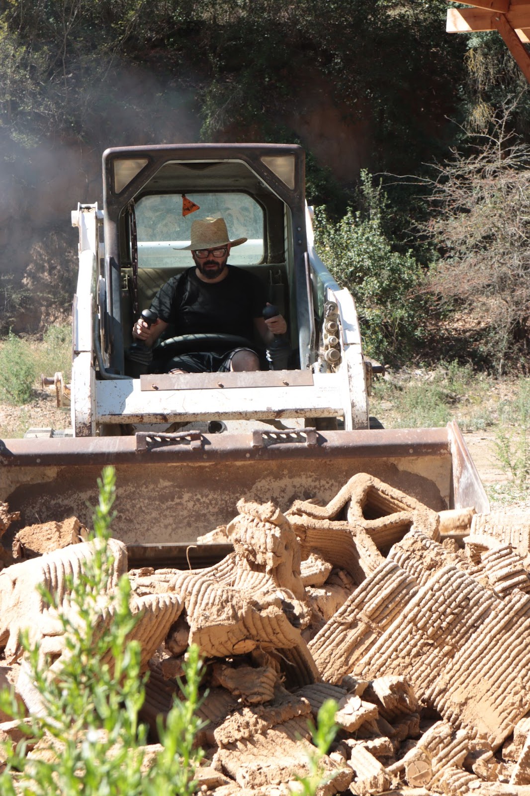
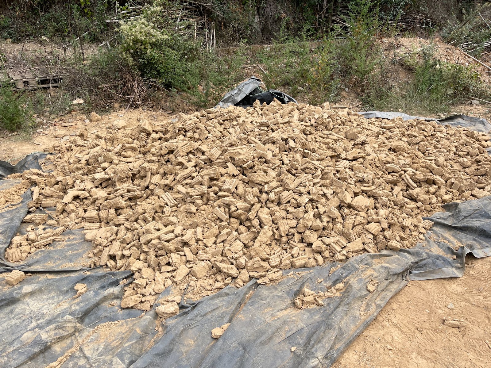
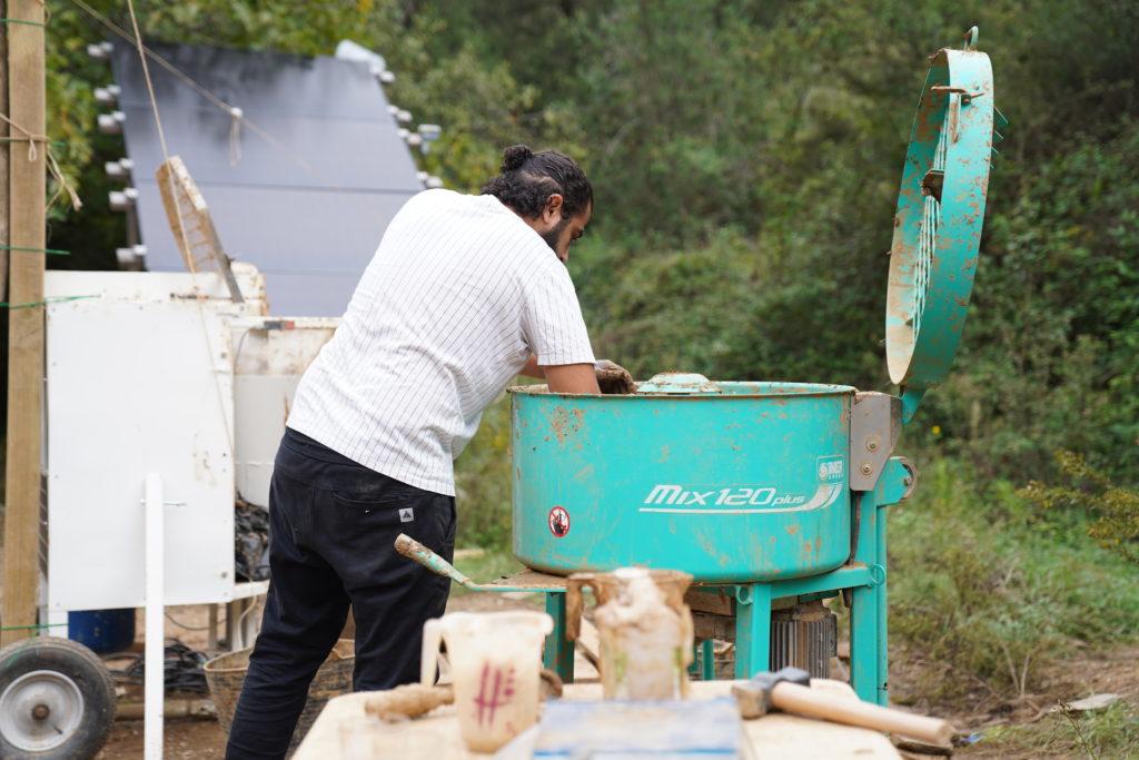
Material Recyclability
The material used for this prototype is directly extracted from the previous one, Volta. Raw earth is a material that is fully recyclable, this prototype also aimed at proving that it is possible to fully reuse the material of a prototype for the production of another one
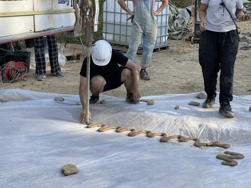
Foundation & Cast
As in the previously mentioned TOVA, the foundation had to be casted out of another material that does not dissolve in water. A negative of the shape was produced, which was then reinforced with lateral pieces, as the weight of the cast is strong enough to push away even a double layer of earth. The cast reached the first 300 mm
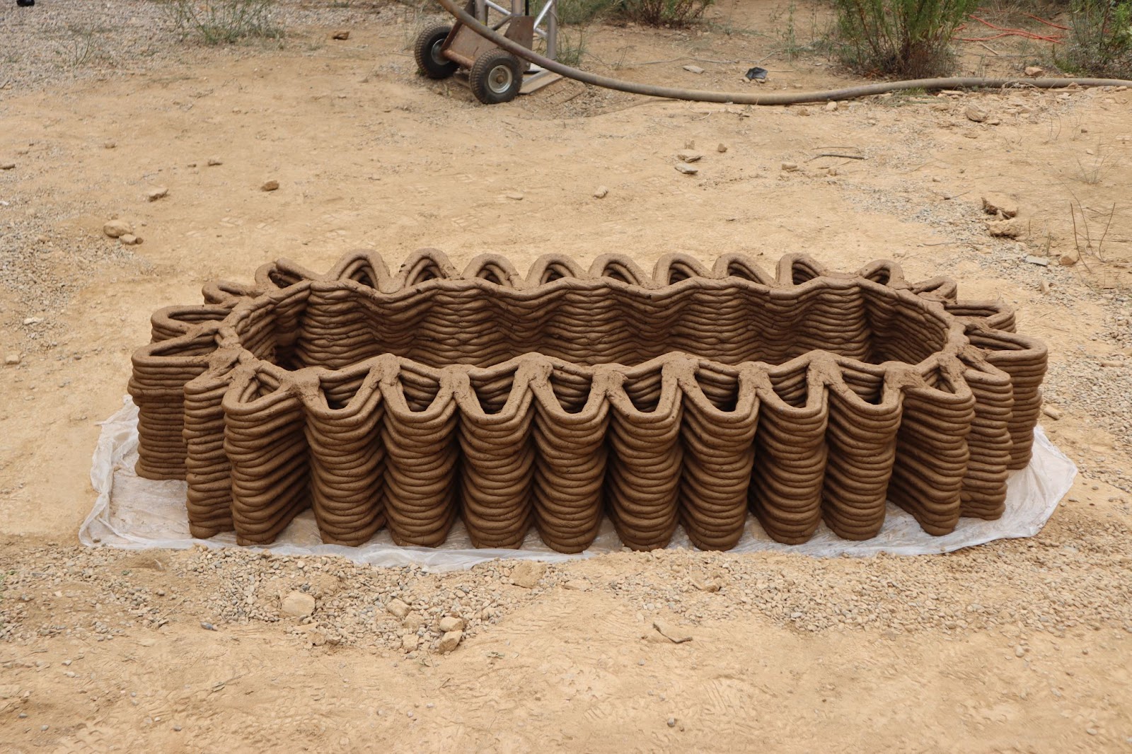
Overhangs
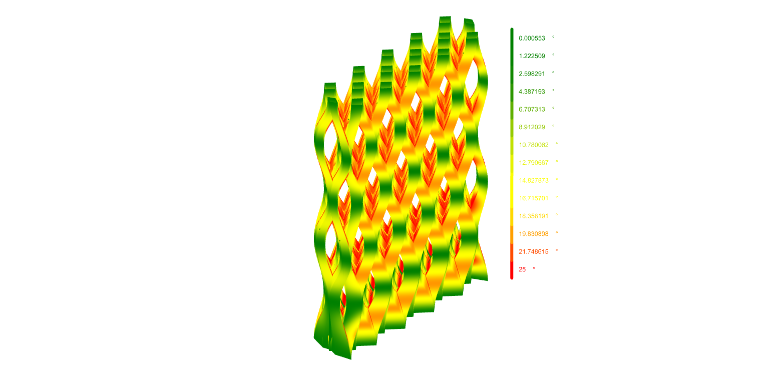
The prototype was globally designed never to exceed an overhang of 25°, regarding the thickness of its members. This simulation was done using an angle analysis of the object. Comparing its surface angulation with the vertical.
Edges condition
Such geometries that are based on a grid system face edge conditions. Meaning that at some points of the model, they don’t have any neighbors to support them. The overhangs then start to exceed the printability limits. In summary, the edges are weaker. To solve that, the grid on the edges is scaled to 33% of its original size and its section thickened along its height. The combination of those factors drastically decreases the overhang angles while keeping the morphology of the geometry intact.
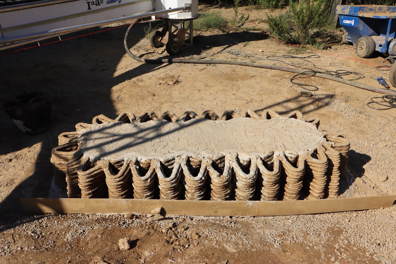
Mesh grids
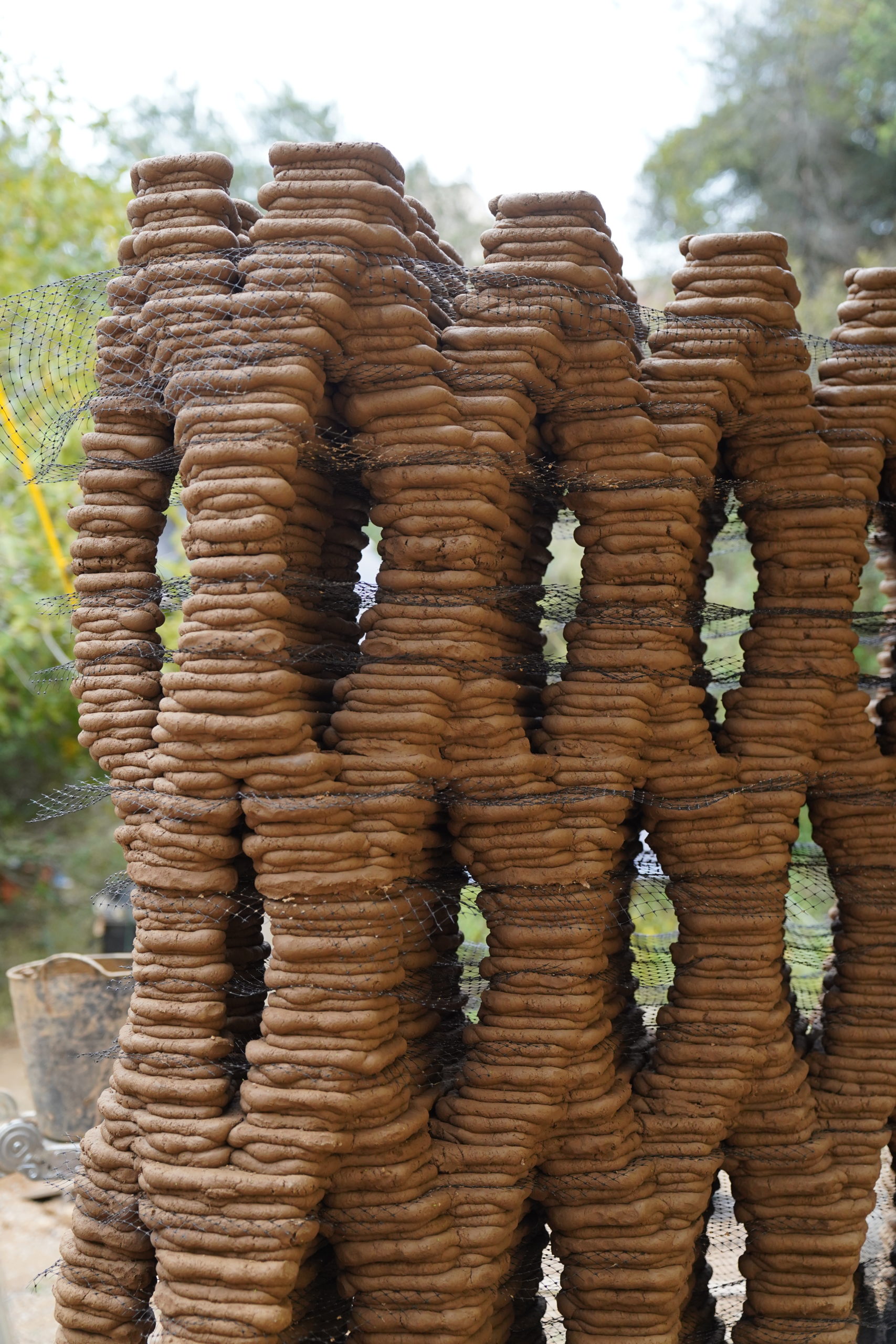
A geometry with so many independent members can have a tendency to lose stability, move and loose its position, making it impossible to print any extra layer on top.
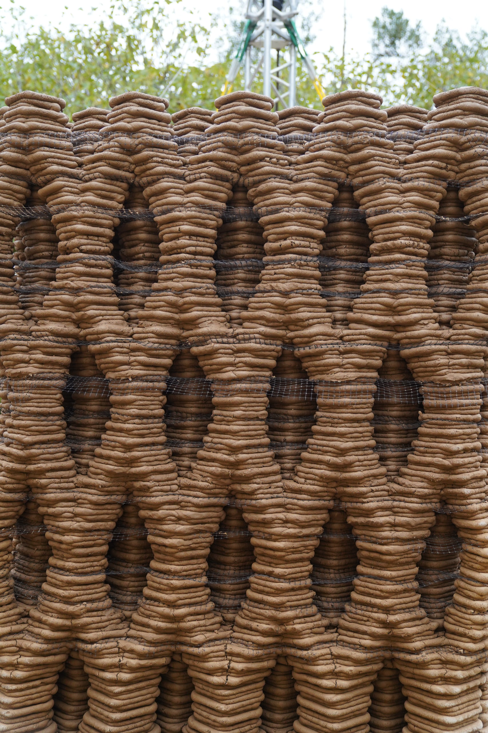
We applied some reinforcement to specific parts of the project by inserting grid meshes. These grids can be found out of any material that is not elastic. The proper sizing would be between 10 and 20 mm for the grid cells, with a minimal wire thickness. Too much material will decrease the binding between the layers, resulting in collapses, not enough will not create a homogeneous reinforcement.
Offsets
Evey 3 layers, the toolpath was offsetted by 10mm. Like in TOVA, this will enhance water protection and homogenize the esthetic of the print. It proved to be useful to counter some extra motion that happened during the printing process.
However, in some particular cases, the next layer was smaller due to a gradient in geometry scale. The combined effect of an offset lower layer with a smaller upper layer would make that upper layer not to have enough support to be printed. This was tackled simply by adding extra material as support.
Approach curves & curve order
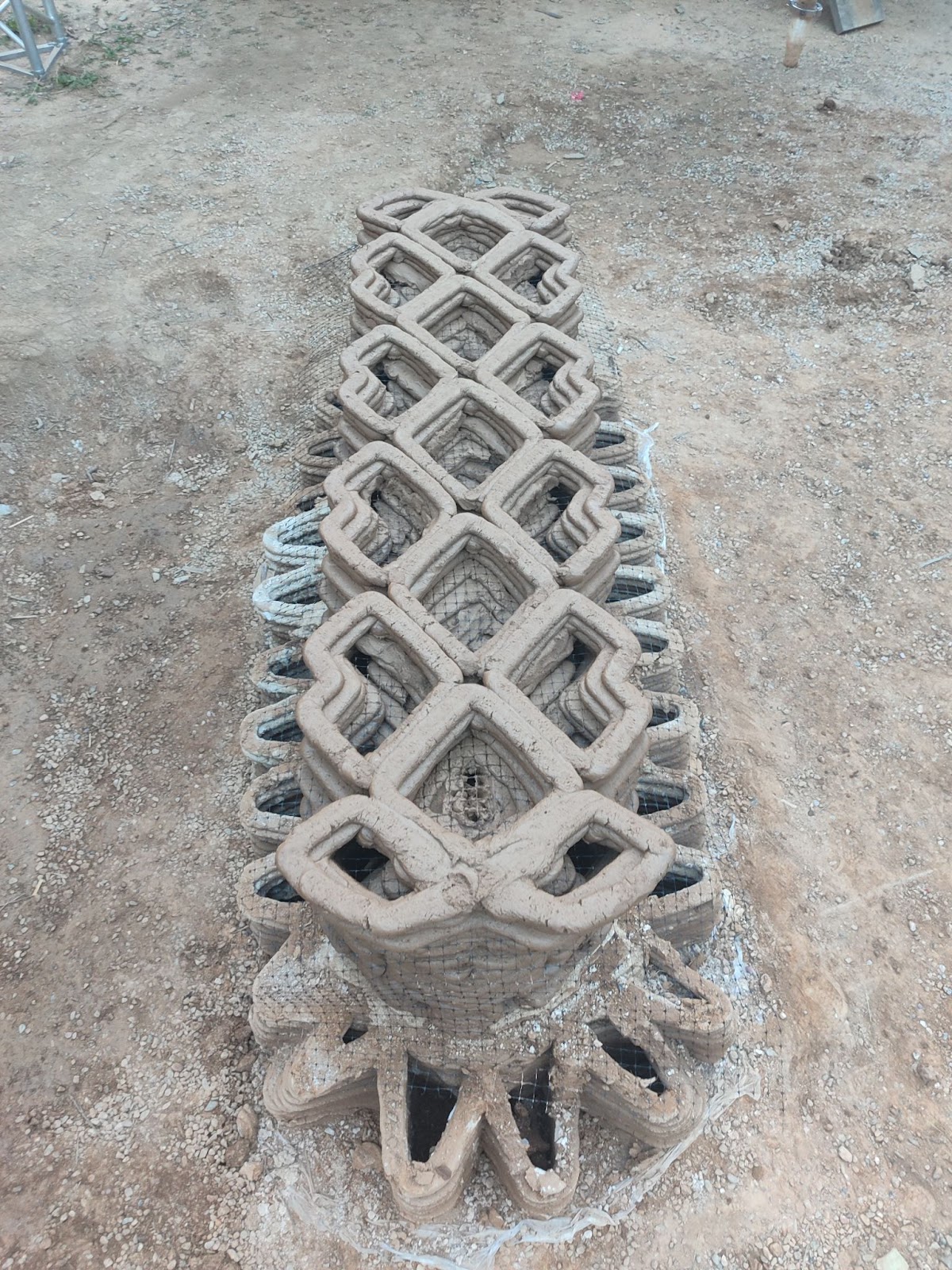
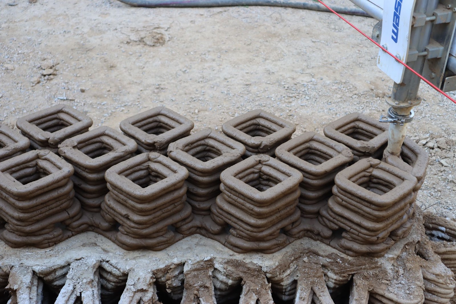
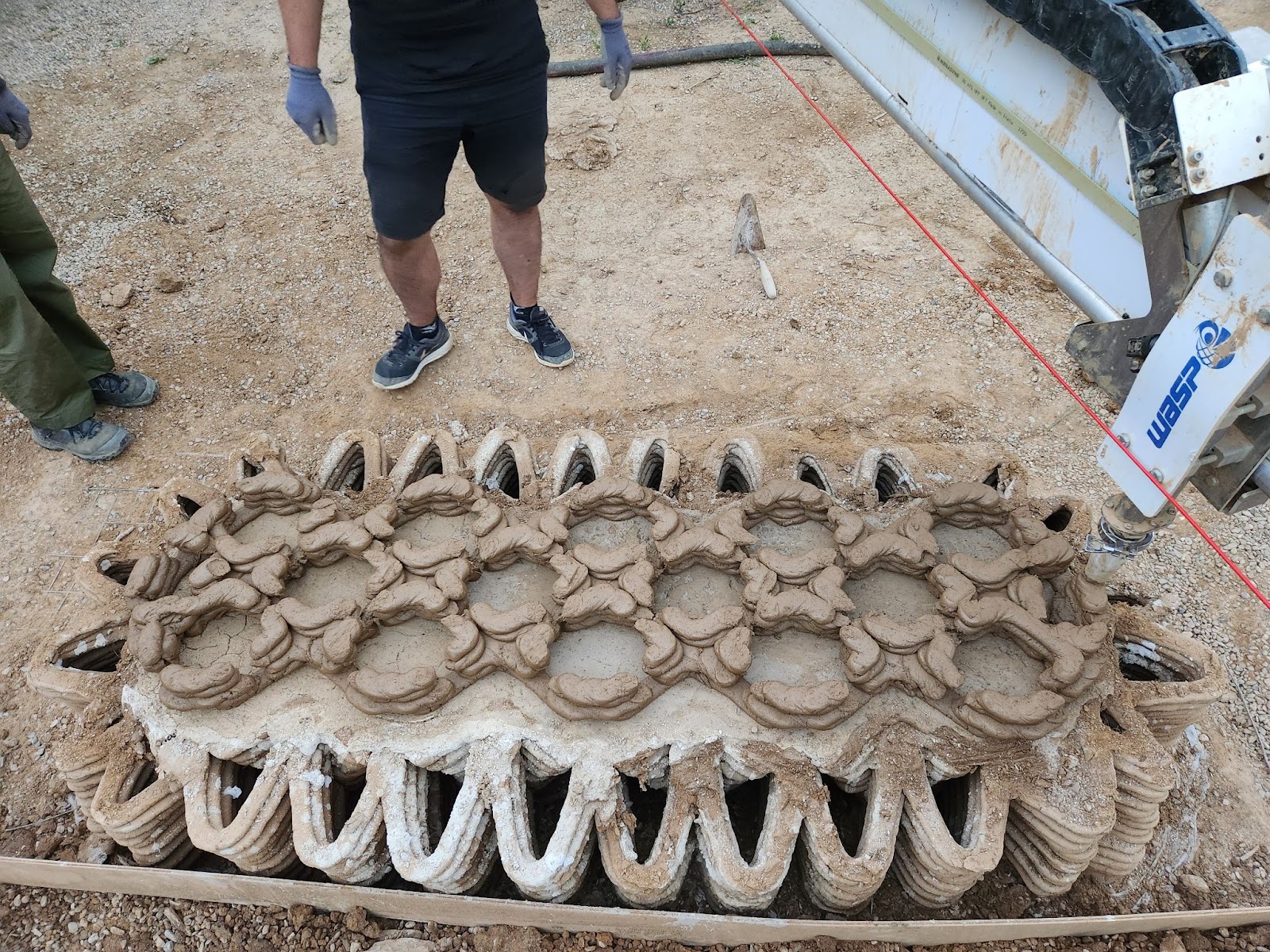
Such a complex geometry requires high precision and delicacy to be achieved properly. During the print, a specific issue was faced: the nozzle of the printer would drag and move the unequilibrated pieces. The solution to that was to print the cells in a very precise order.
In Red, the start of a layer, in blue the end. The start of each cell is always further away from the previous cell. So, when the nozzle is back to the start point, it doesn’t go over the already printed object and moves to the next without collision.
An extra addition to this technique was to add an approach curve of 15mm. This would ensure that the print was in good quality when the actual “geometry” starts. To improve workflow speed, the organization of such a layer is flipped after each layer.
Ventilation
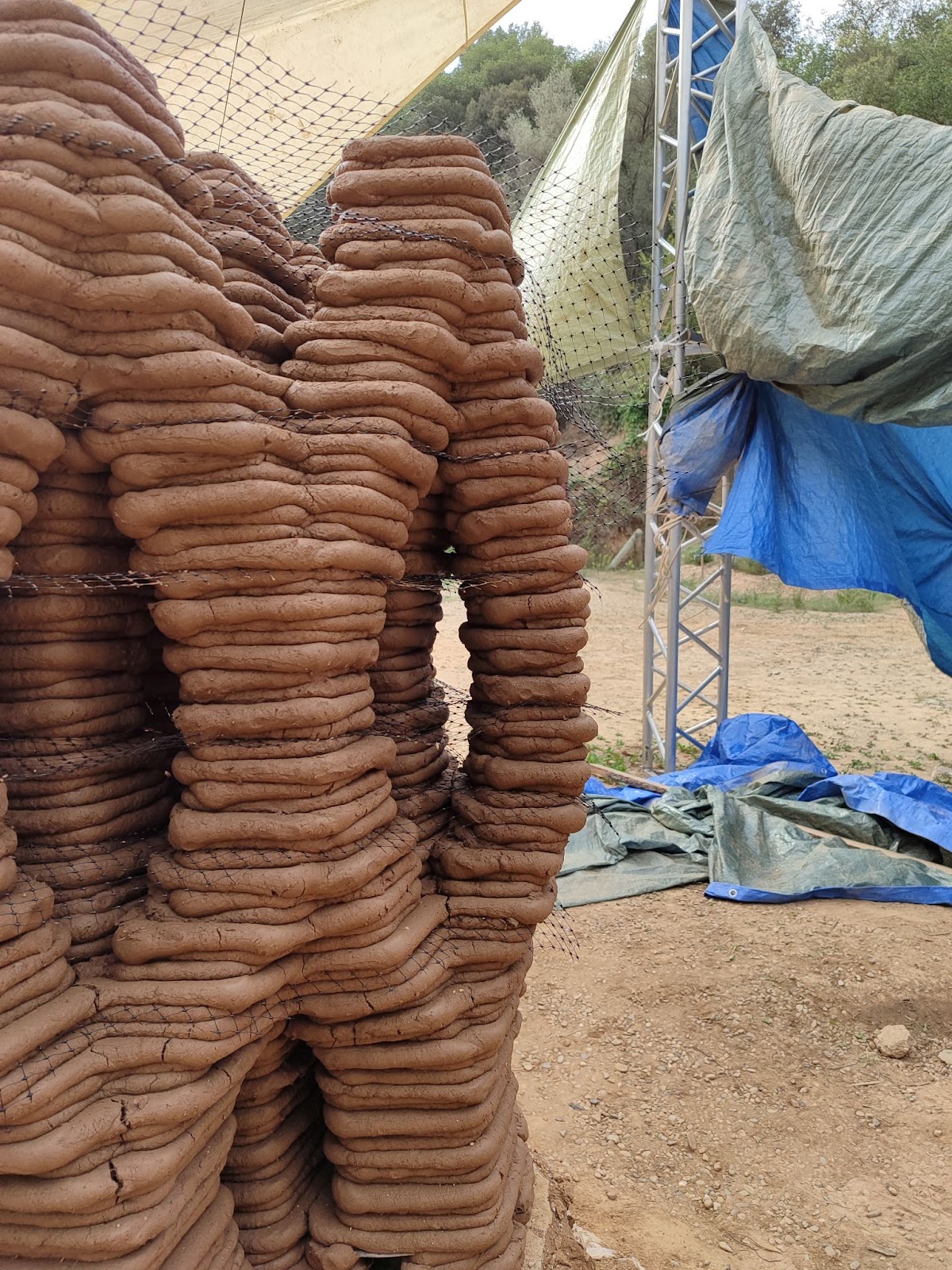
To dry properly, an Earth 3d printed object needs to be properly ventilated on the inside. This why the geometry is empty. However, to sustain proper ventilation it is needed to be able to bring the air from outside. In VOLTA and TOVA, this was done by inserting tubes in the foundation, from outside to inside the geometry, providing the airflow. This time the airflow opening was inserted straight away inside of the toolpath, creating a small geometrical opening at the very base of each of the geometry’s legs, between the cast and the earth. The goal is to avoid the need of any extra material to provide airflow as it would become an integrated design feature.
Conclusion
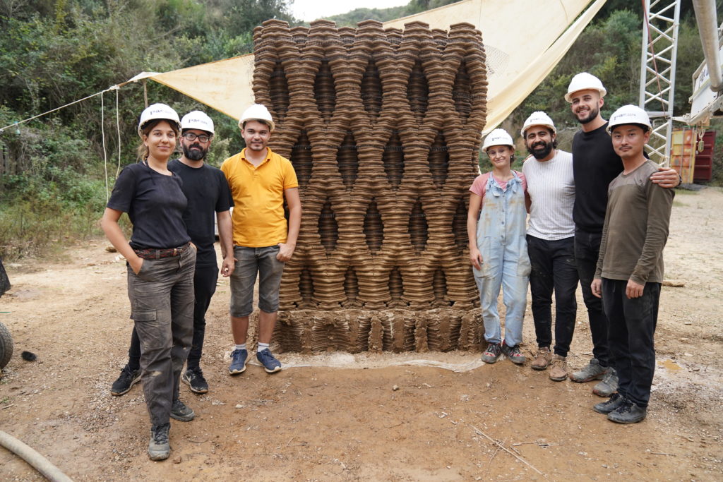
All in all, from the cast to the last layer, the project took around twelve days to be printed. This represents around 1300m of printed earth and two tons of material. It reached 2500 mm of height, for a length of 1600mm and a width of 400mm. Alongside this prototype shows that it is possible to achieve delicate geometries using raw, and reused, rough materials in large scale 3d printing. The challenge to overcome the things that neither the machine, nor the material are used to be performing. There was an esthetical challenge as well: can an architecture of darkness turn into an architecture of light?