This academic year, the 3DPA program focused on the theme Performative Earth Construction, guiding the work from research to design and construction.
Following the projects Tova and Texit pavilions, two enclosed spaces built on the Forest Campus, the aim is to explore how 3D printing with earth can be used on a larger scale while responding to climatic needs.
The primary objective this year is to design and construct a 7-meter-long performative wall that functions as an integral element of a larger enclosed space, enhancing the interior comfort. This wall integrates outcomes from interdisciplinary research into thermal Transmission, self-shading, natural ventilation, structure, and surface water redirection.
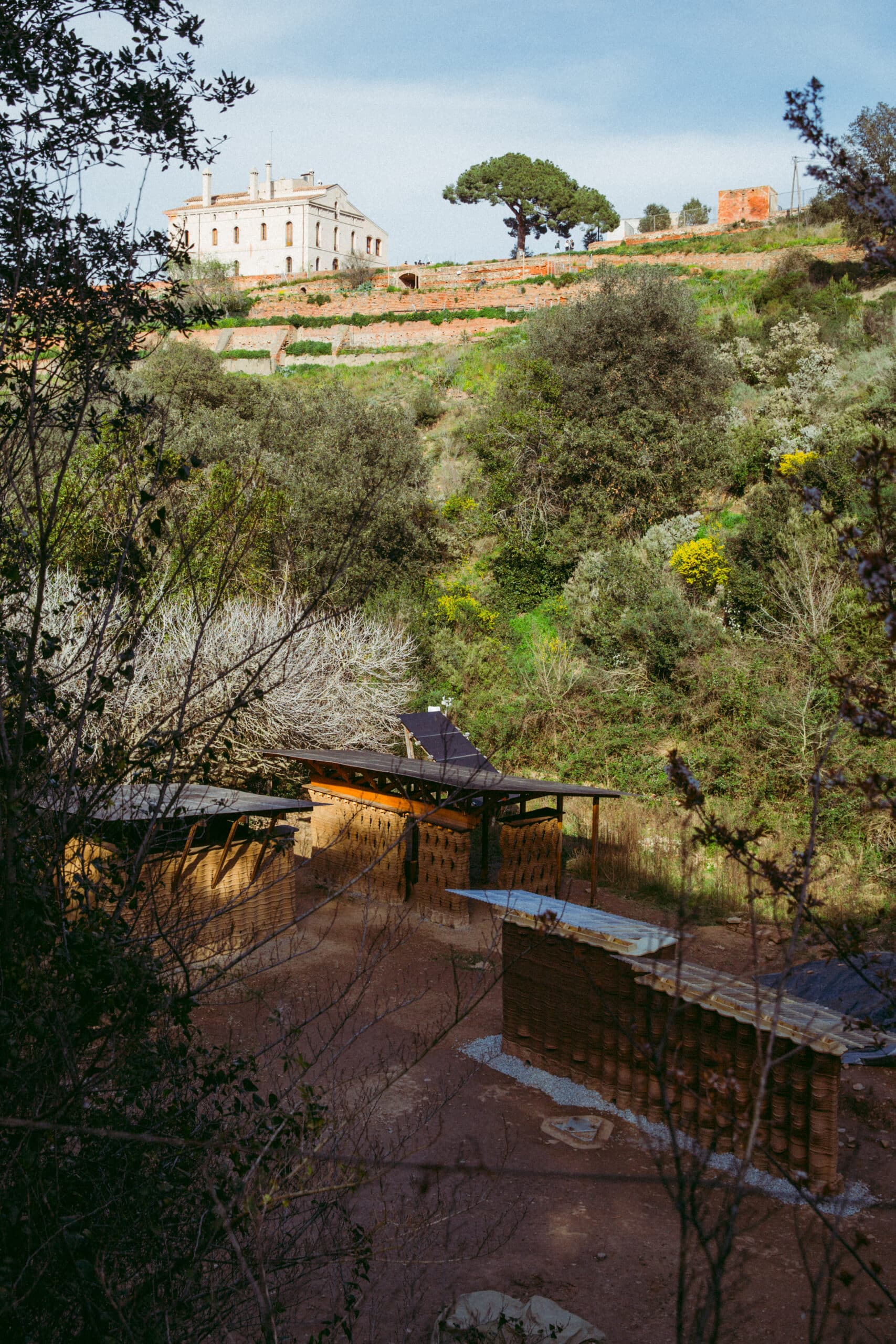
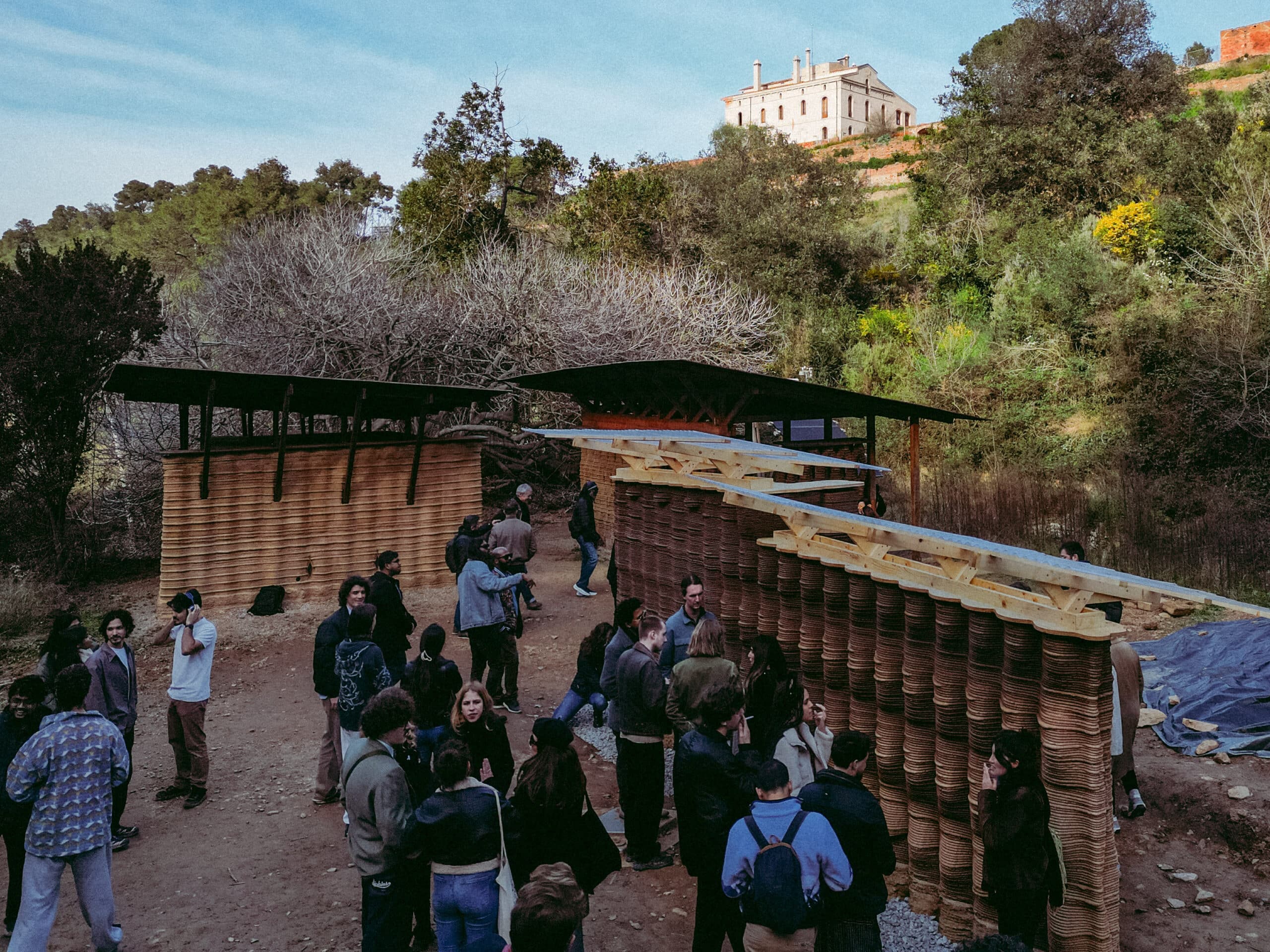
Located at Valldaura Labs in Caserolla Park, Barcelona, HELIA marks a new chapter in the exploration of 3D-printed architecture for the Mediterranean climate. As an evolution of the TOVA and TEIXIT pavilions, HELIA, it introduces a bedroom and a living room, furthering the vision of sustainable, earth-based construction. Combining indoor and outdoor elements, the project strengthens the learning environment at Valldaura Labs and remains a valuable tool for future student work.
The buttresses were strategically placed to support and differentiate the 7-meter-long wall, ensuring both structural integrity and architectural intent. Their positioning was informed by climatic principles, spatial integration with existing structures, and practical construction constraints. The wall’s alignment and segmentation were carefully planned to accommodate the WASP Crane printer’s reach and maneuverability, optimize cost-effective use of existing foundations, and meet structural and time limitations.
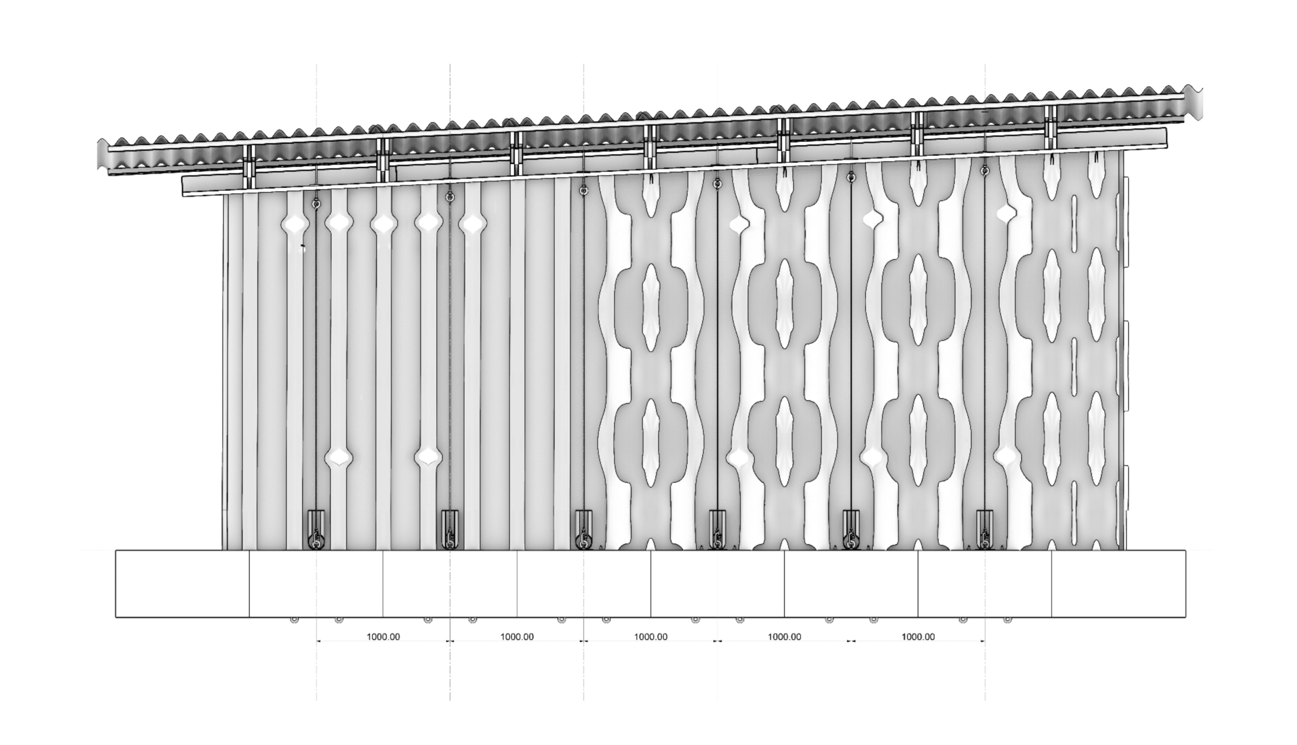
Performative Wall
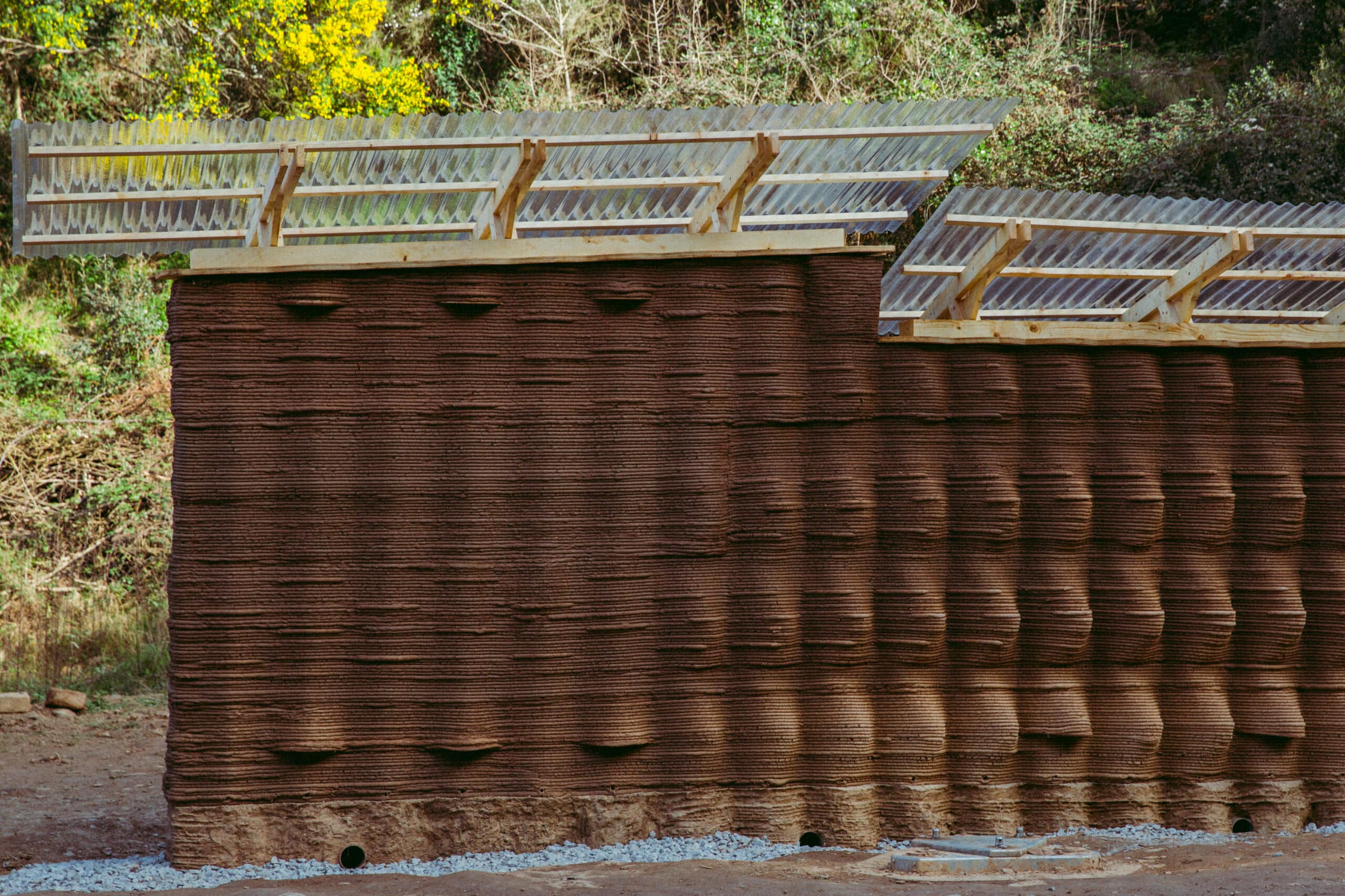
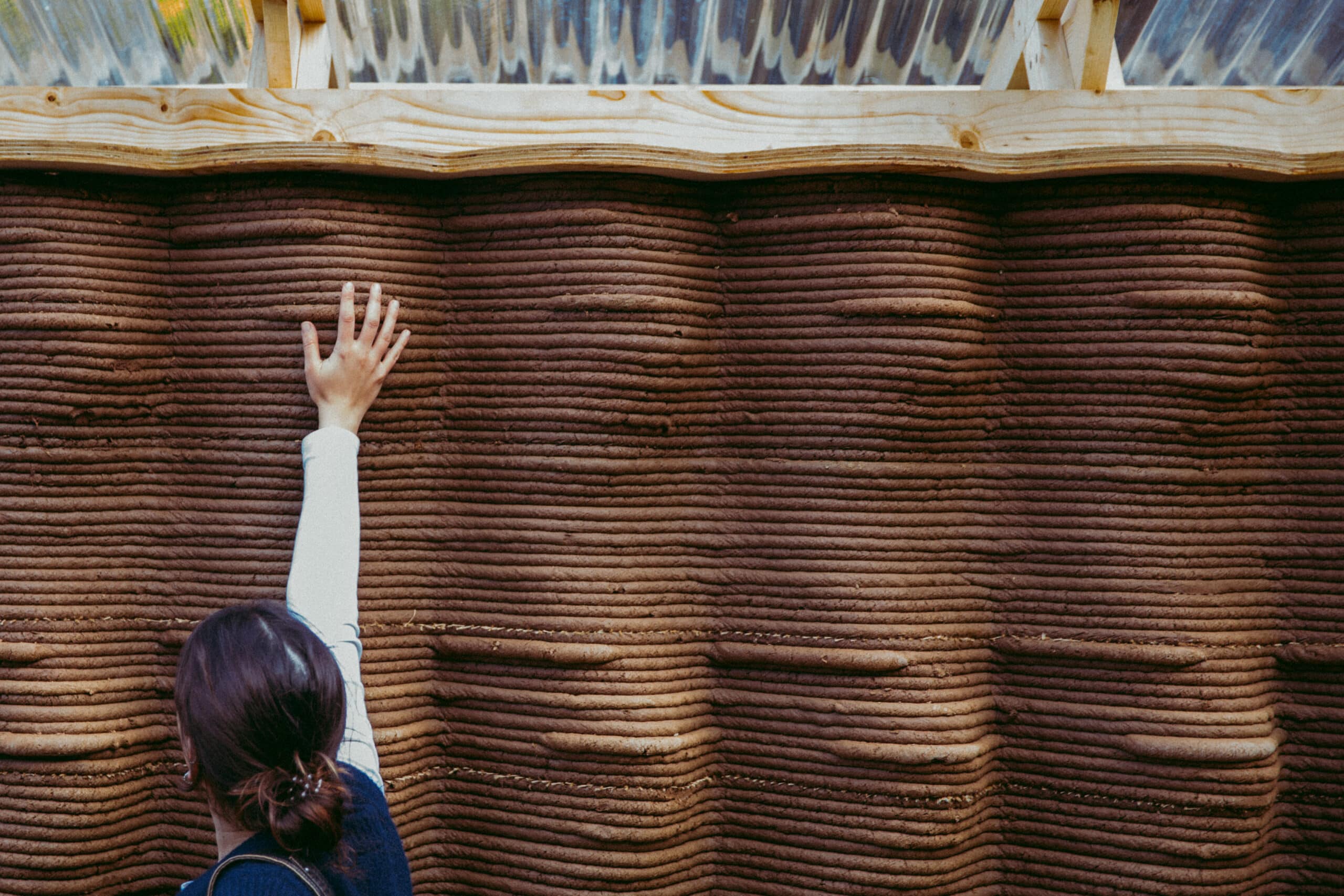
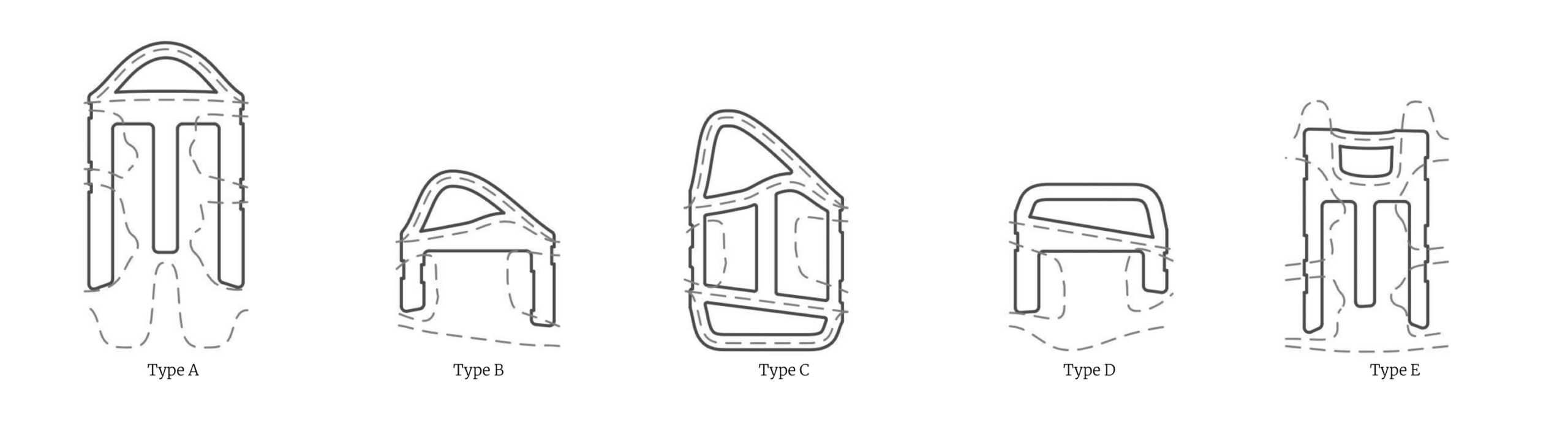
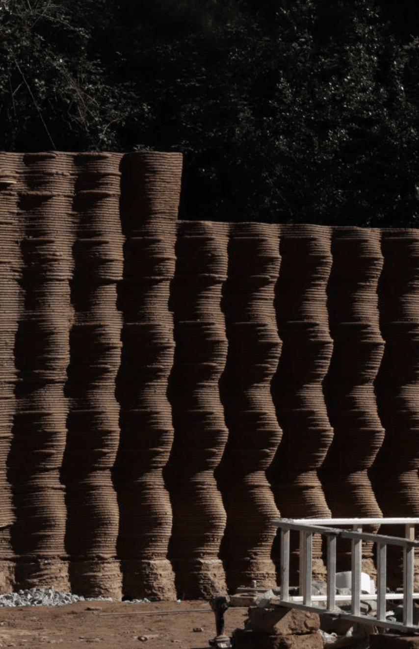
The development of the wall pattern was a culmination of all the Researches developed, was modified to match the spatial and structural functions arising from the orientation and anchoring. The different strata of the wall were treated differently according to the functions they were subjected to. Starting with outermost strata, the pattern profiles were modified with a gradient that allowed the transition from completely flat period to a self shading surface, that also translated to a transition from bedroom to a living space along the southern direction.
The design reflects the different thermal needs of the two spaces: the living room, used during the day, benefits from a self-shading wall to reduce heat gain, while the bedroom, primarily used at night, stores solar heat during the day and releases it after sunset, eliminating the need for shading.
Further, the middle strata of the wall was assigned with both thermal and ventilation performative periods housing the roof anchoring profiles. The pattern profiles, where the cables would be driven through, were stretched along the vertical axis to create tolerance for discrepancies caused by the shrinkage of the walls or movement of the roof structure.
The transition from experimentation to execution involves refining concepts through iterative testing, digital simulations, and material studies before full-scale implementation. Initial design hypotheses are validated using computational analysis, including structural performance, material behavior, and environmental adaptability. Prototyping at smaller scales helps identify potential challenges, allowing for adjustments before scaling up. Once optimized, the final construction phase integrates these learnings, ensuring a balance between innovative design and practical feasibility.
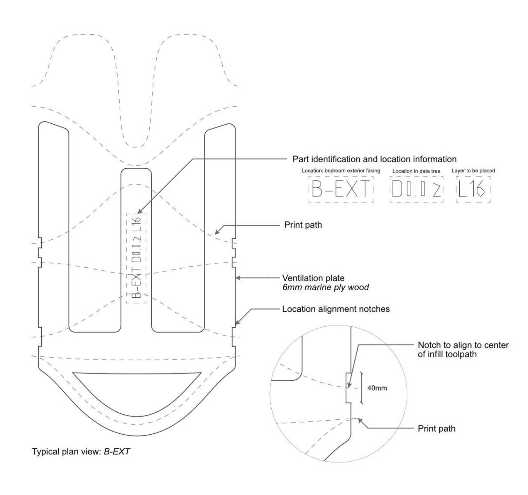
Panel Insert
A custom insert panel was embedded within the 3D-printed earthen construction to enable ventilation
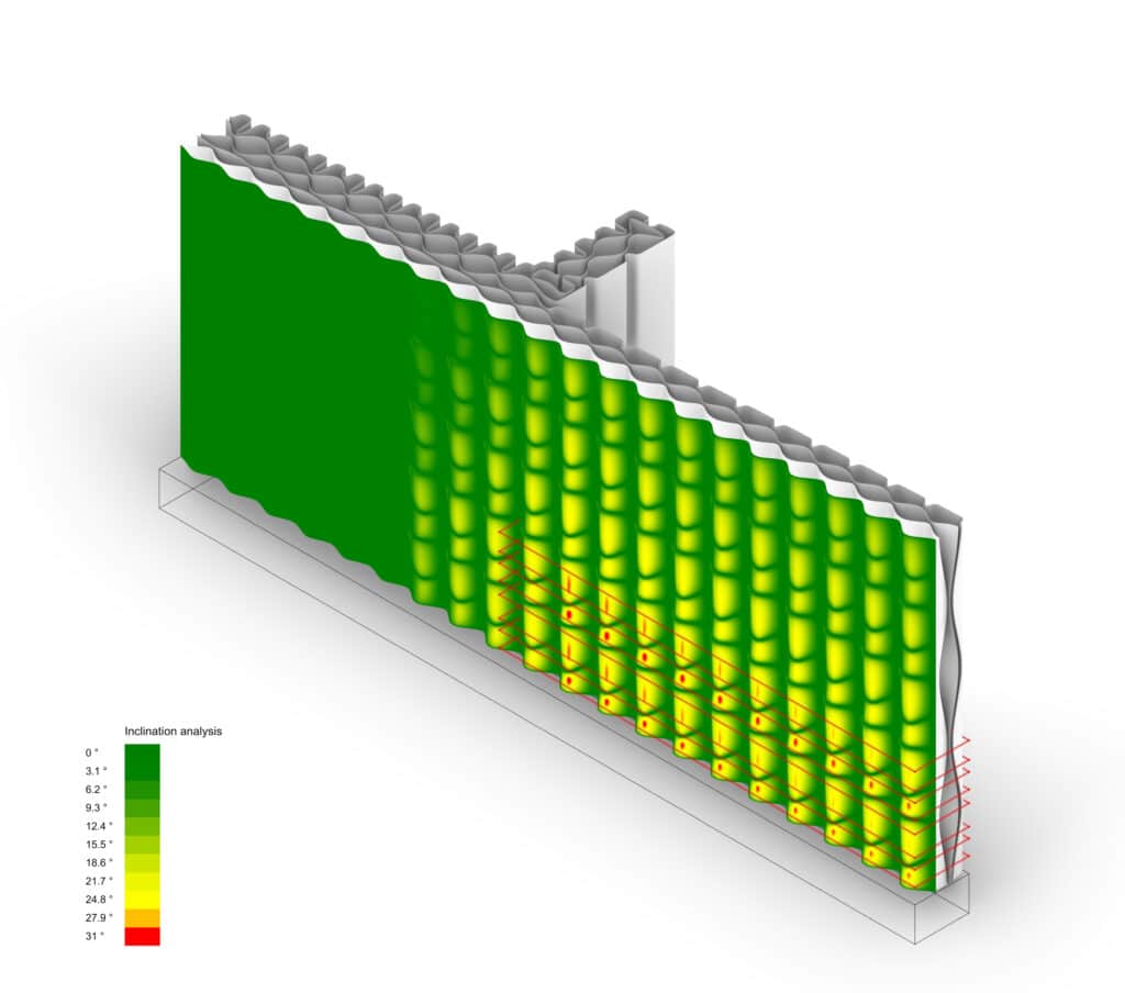
Cantilever Angle Analysis for Optimal Performance
Before execution, the prototype undergoes rigorous digital analysis to ensure structural stability. Parameters such as angle analysis, slenderness ratio, and load calculations are examined to optimize the design. Angle analysis determines stable inclinations, while the slenderness ratio prevents buckling. Load calculations ensure the structure can withstand its own weight and external forces.
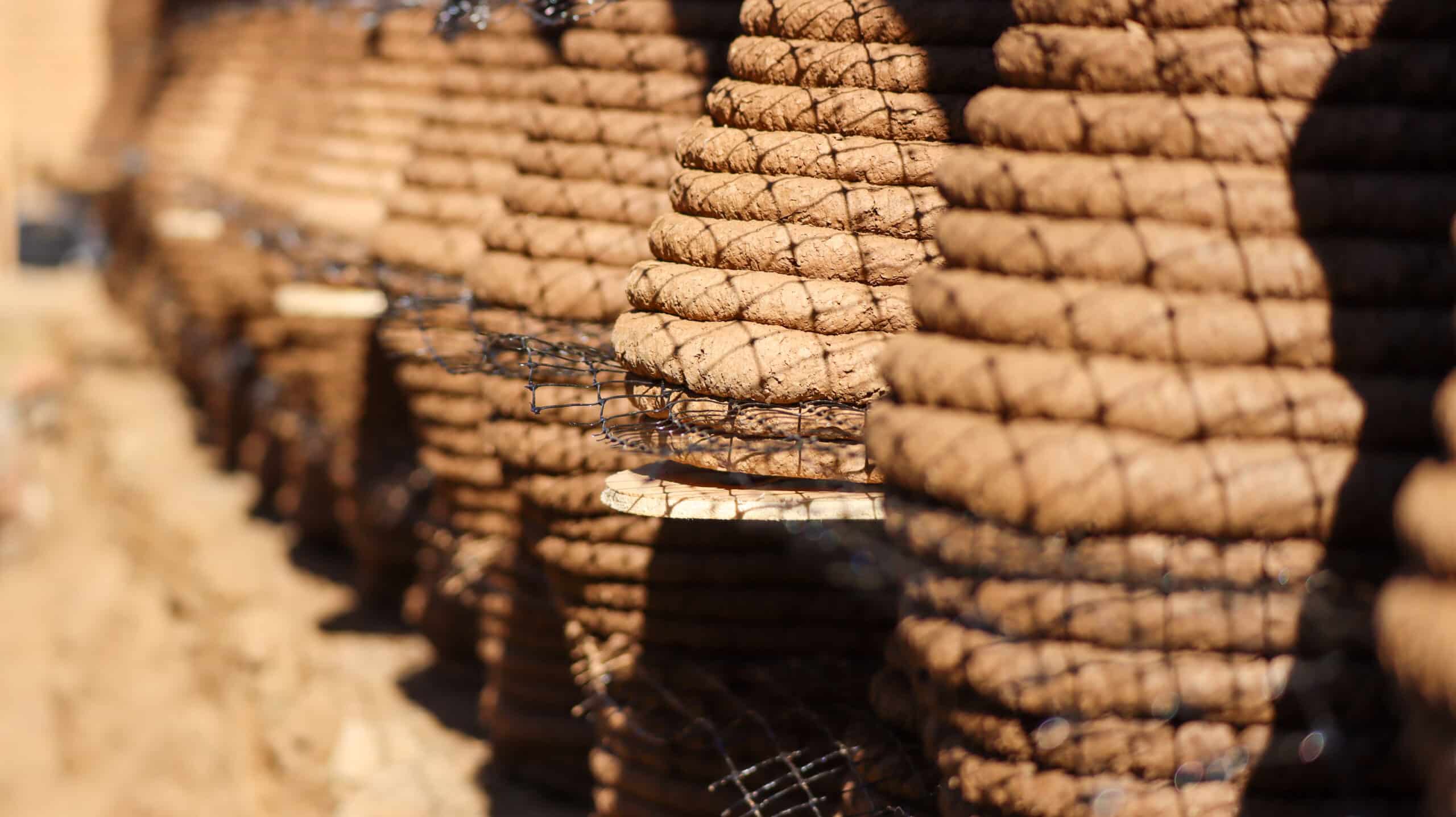
This digital refinement allows us to identify risky areas, where additional reinforcement, such as meshes, can be integrated during the wet stage to strengthen the printed wall. This preparation ensures the prototype is ready to handle real-world conditions before production.
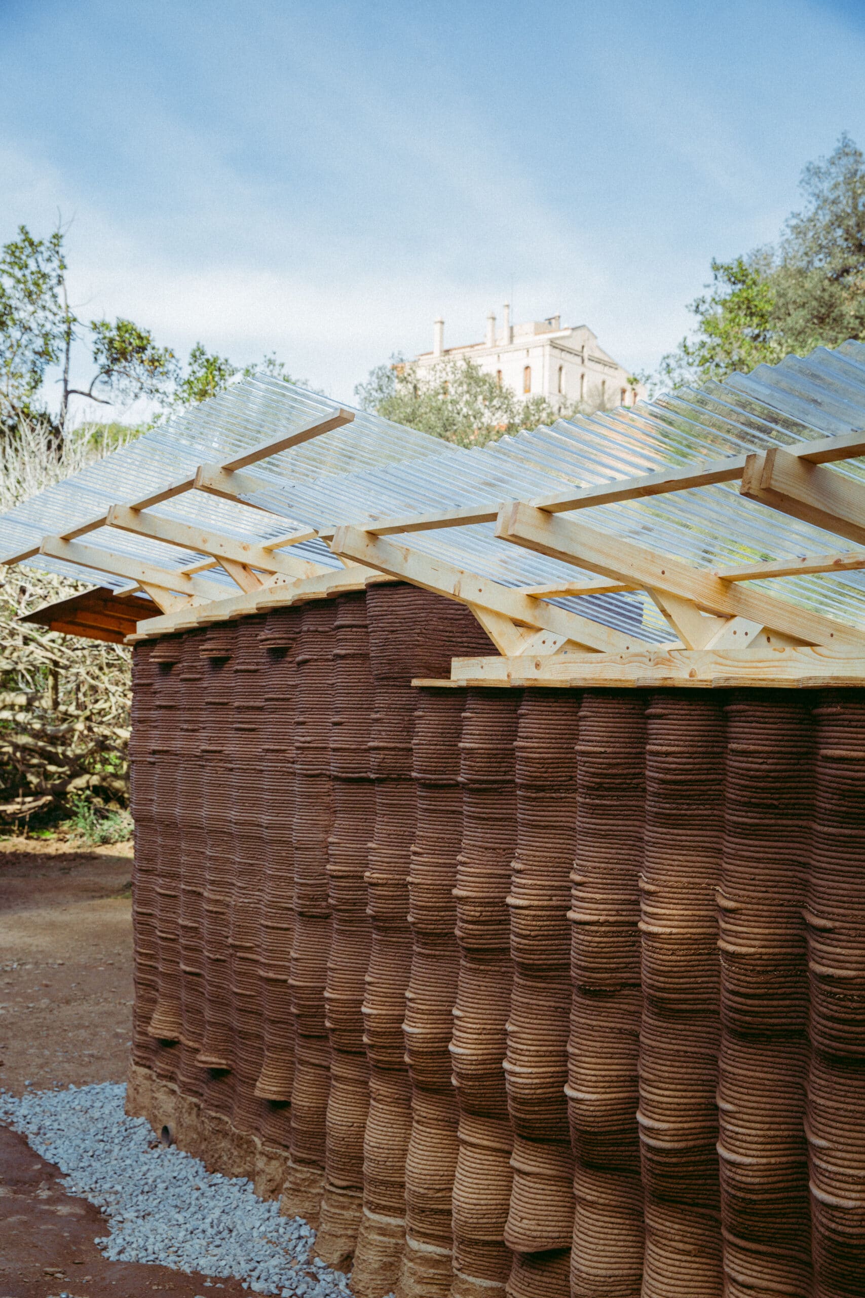
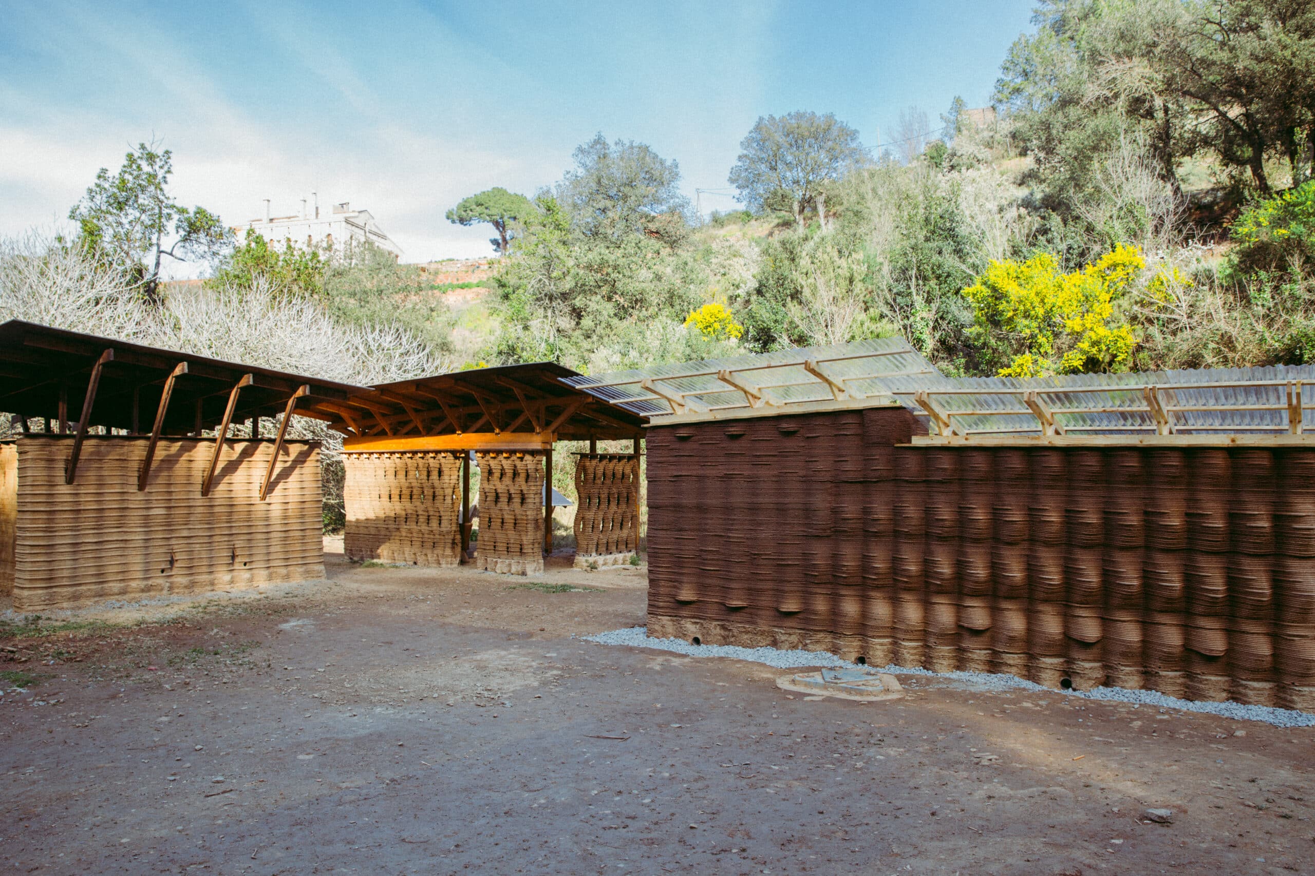
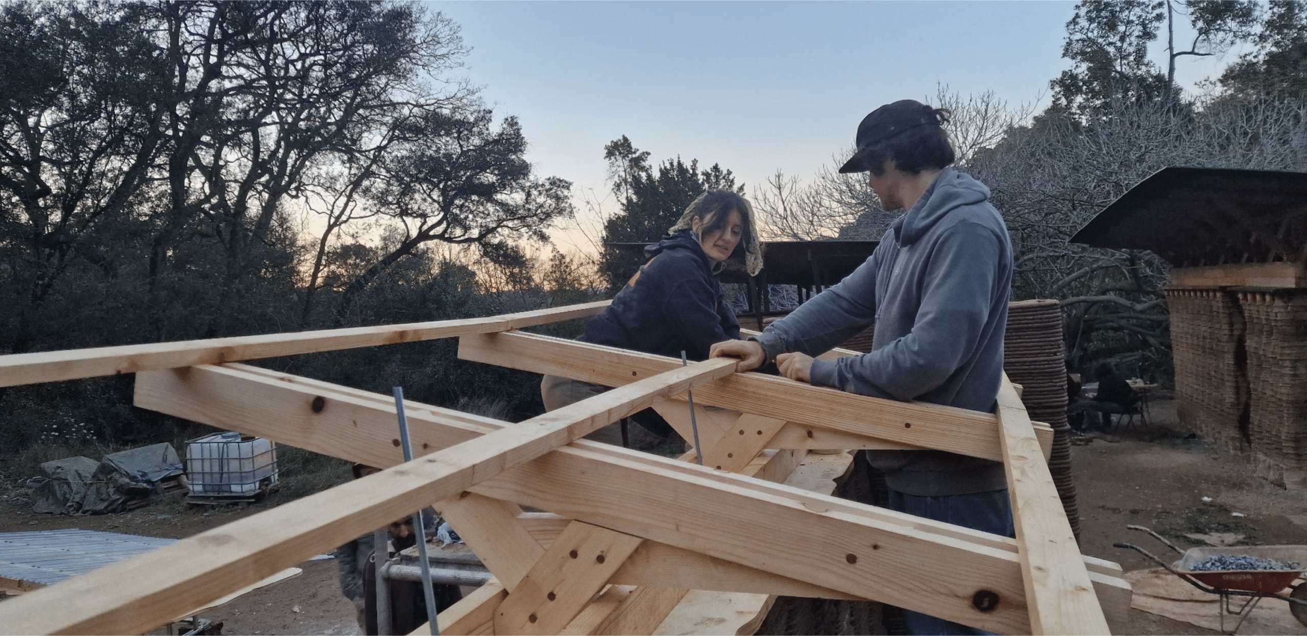
Roof System
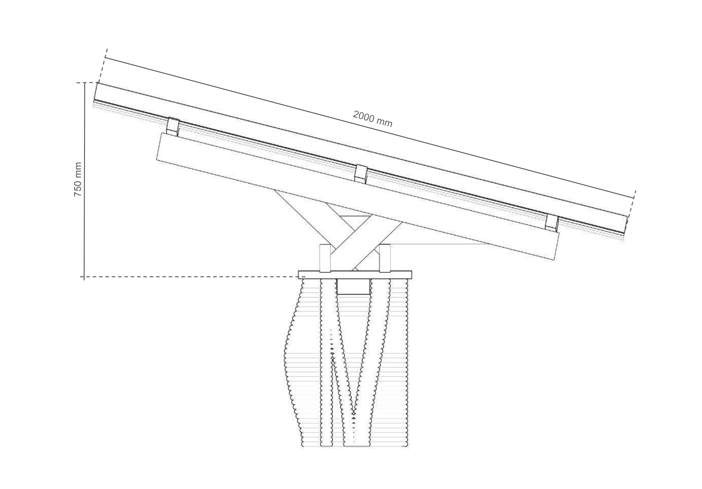
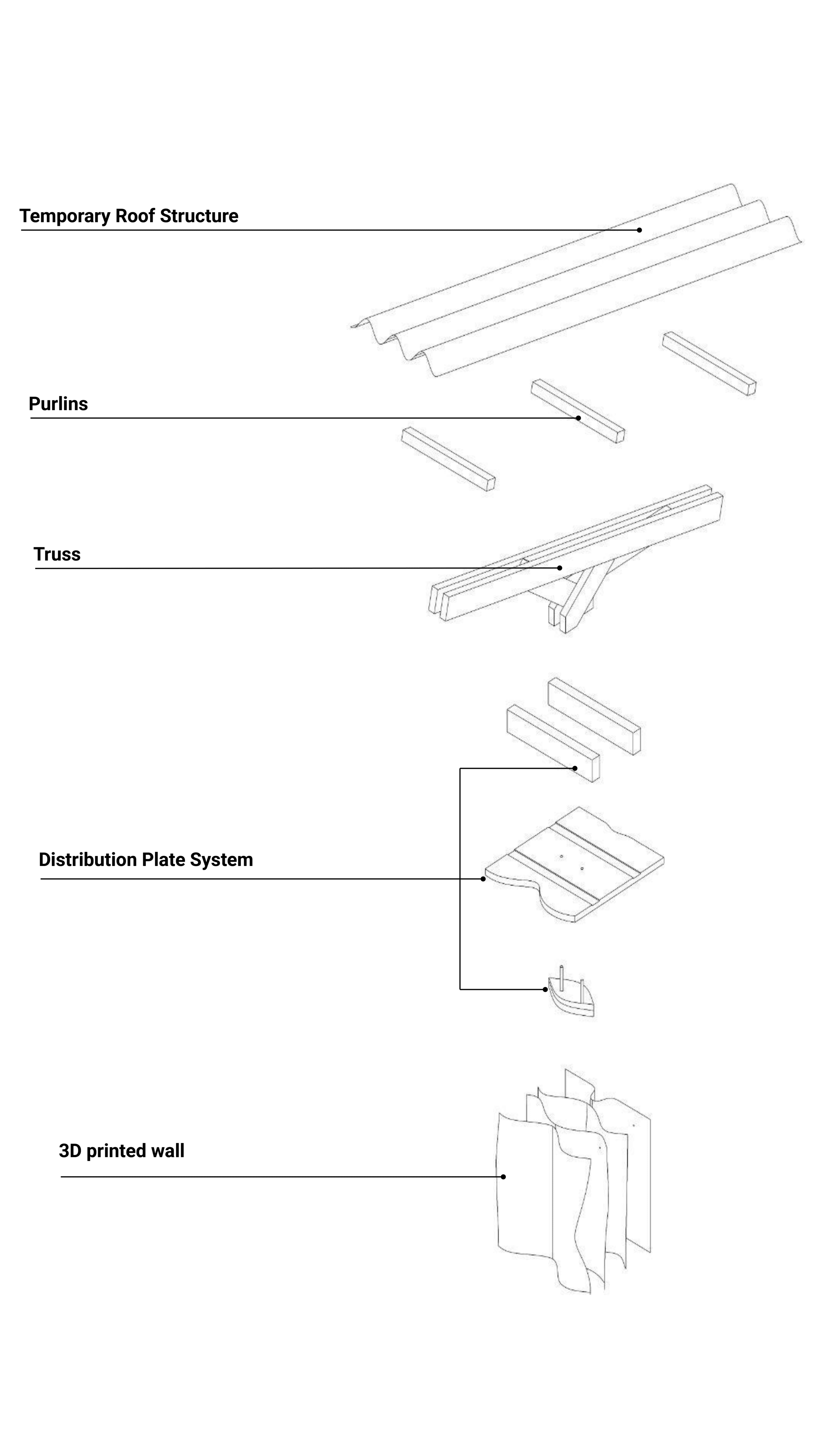
Roof System Is designed to provide protection from rain while allowing sunlight to filter through, emphasizing the performative qualities of the wall. Positioned at a 2.8-degree slope along the north-south axis and an 11-degree slope along the east-west axis, the structure consists of a minimal truss system repeated along its length. A distribution plate evenly disperses the load across the earth infill, reinforced by stringer beams that align the trusses. Tensioning cables within the wall counteract wind uplift forces, while wooden blocks fit into the infill cavities to prevent lateral movement.
Cable connection to foundation
Detail of Anchor connection
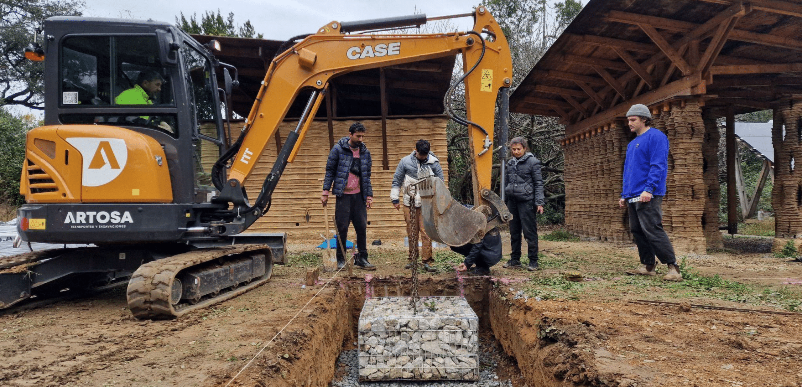
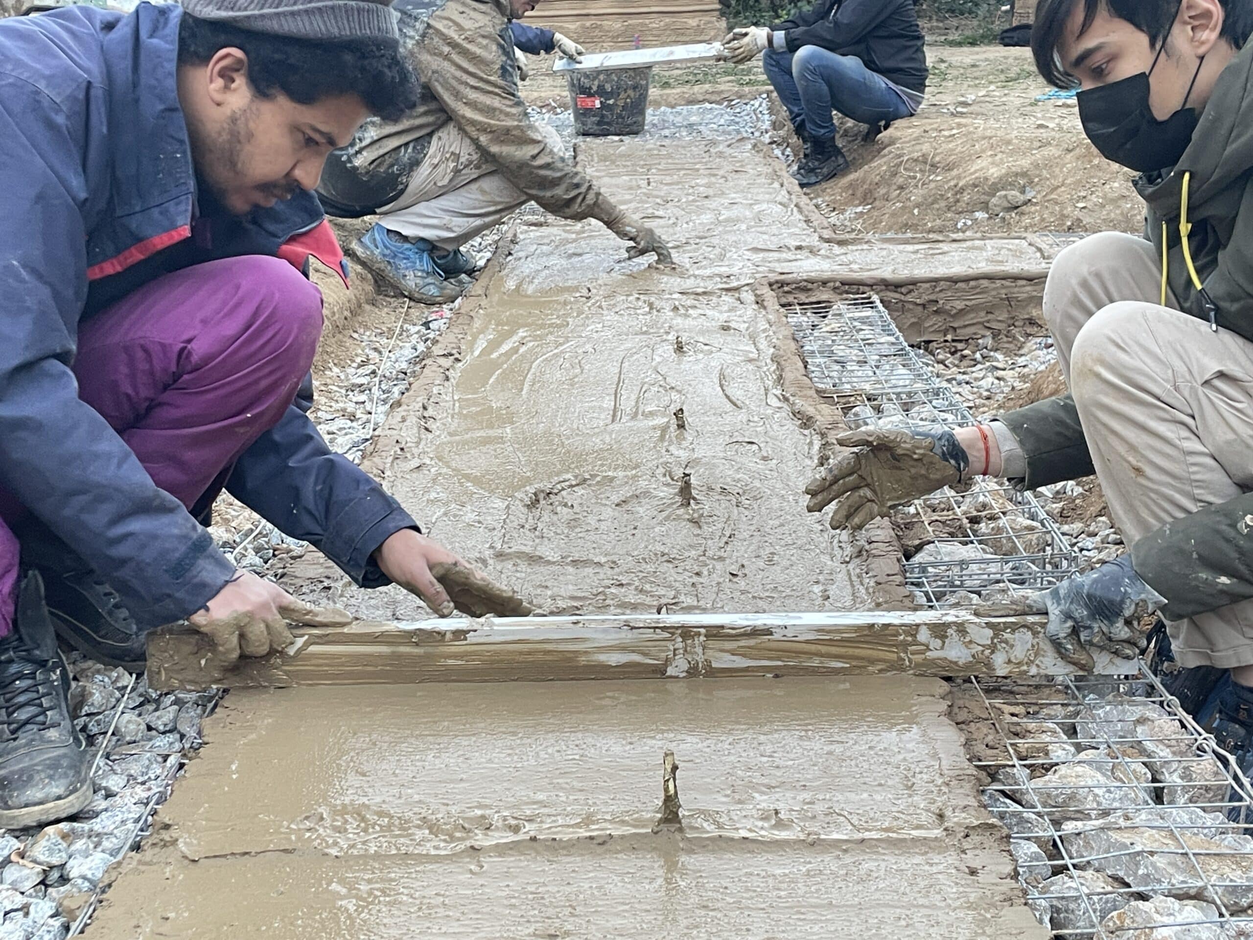
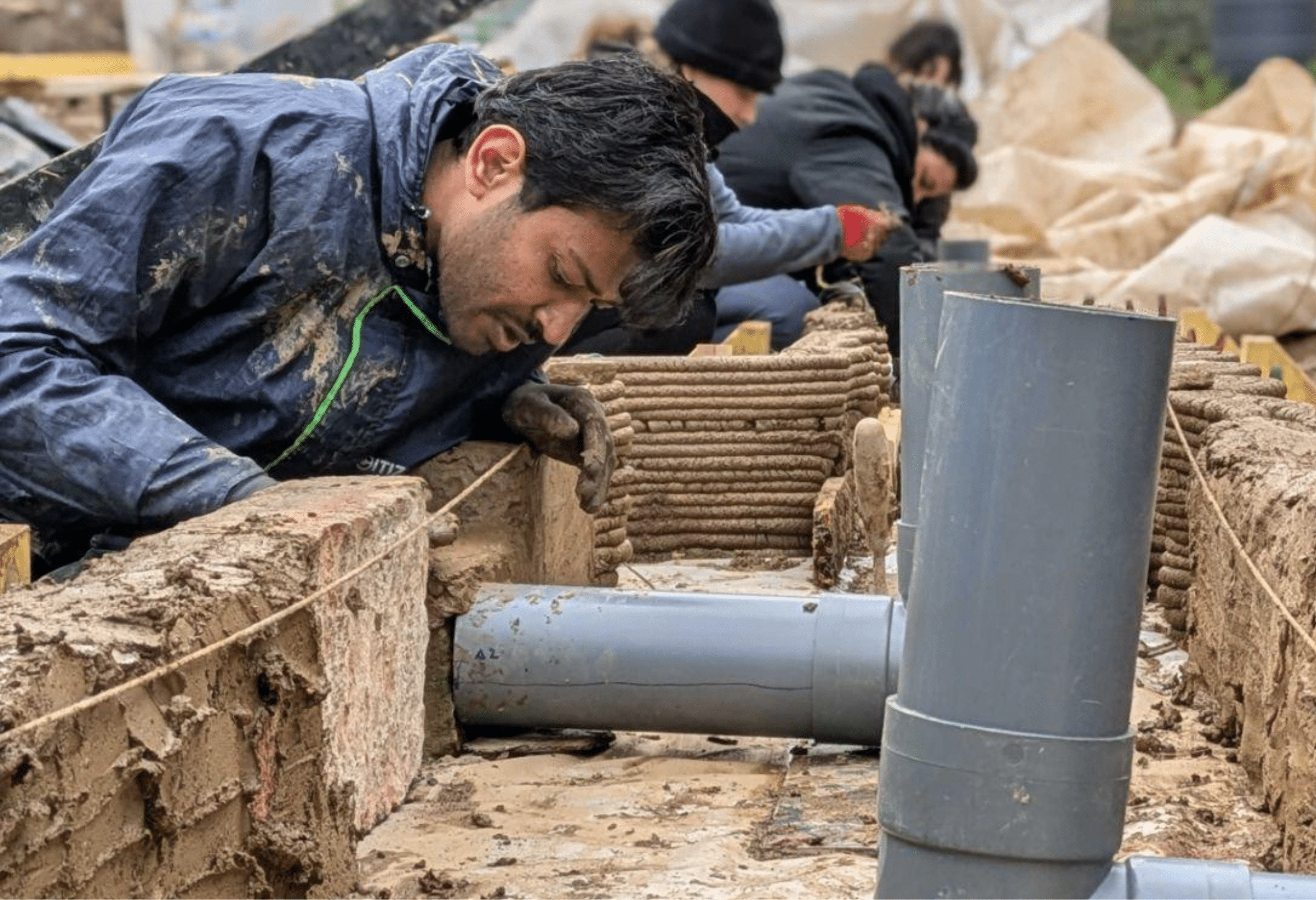
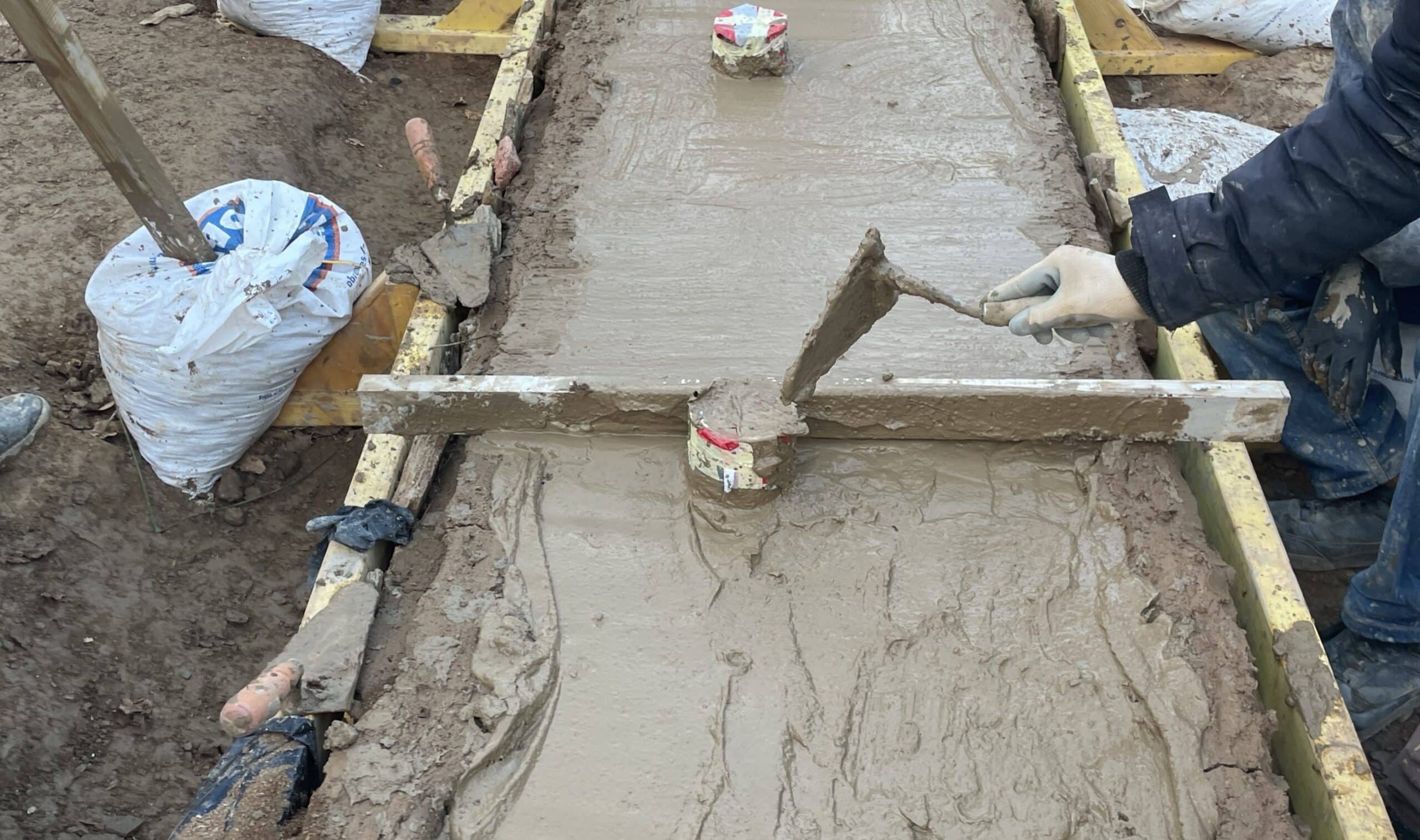
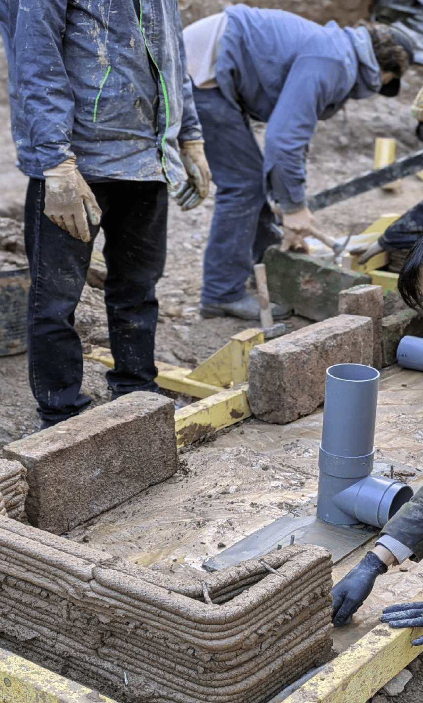
Reusable rock gabions were used as foundations for the two walls. A “plinth” or footing of poured concrete was constructed on top of the gabions to create a waterproof structure in contact with the ground. The plinth was constructed by 3D printing a formwork from the same earth that the walls are printed with, where the concrete would be cast. Before casting, a rebar lattice of 20cm by 20cm cubic cells was installed together with the PVC tube assemblies used to create cavities for the installation of the tension cables.
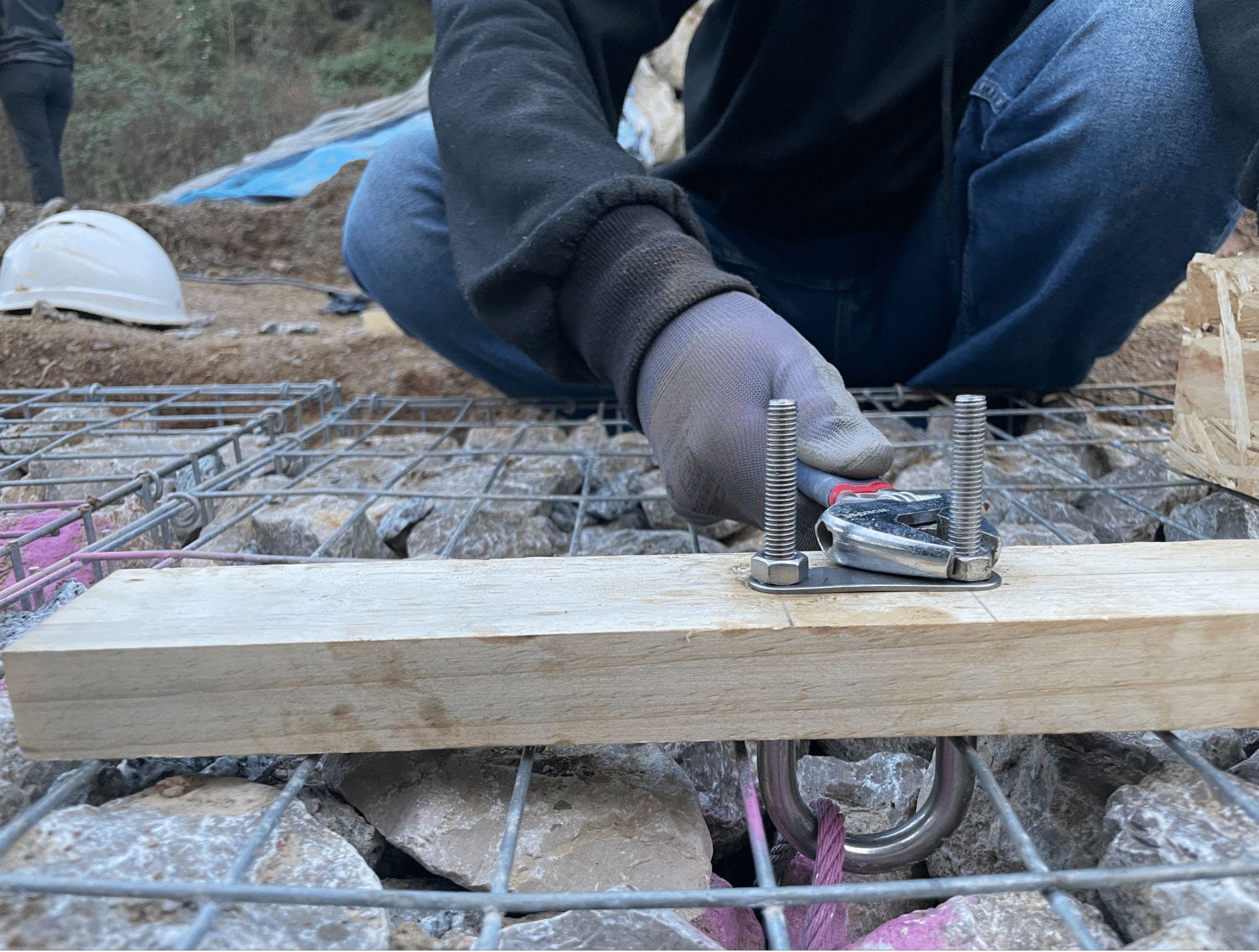
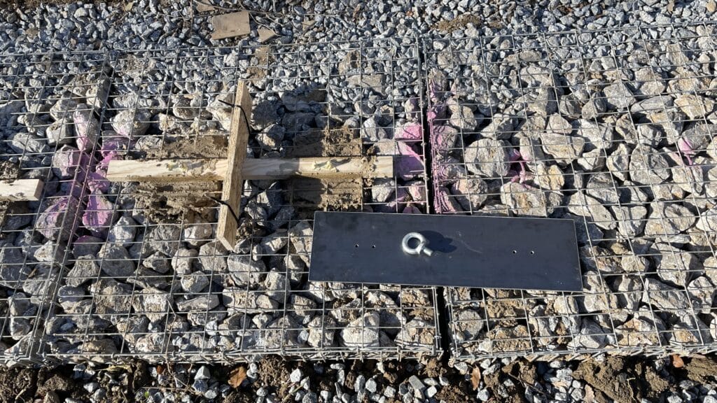
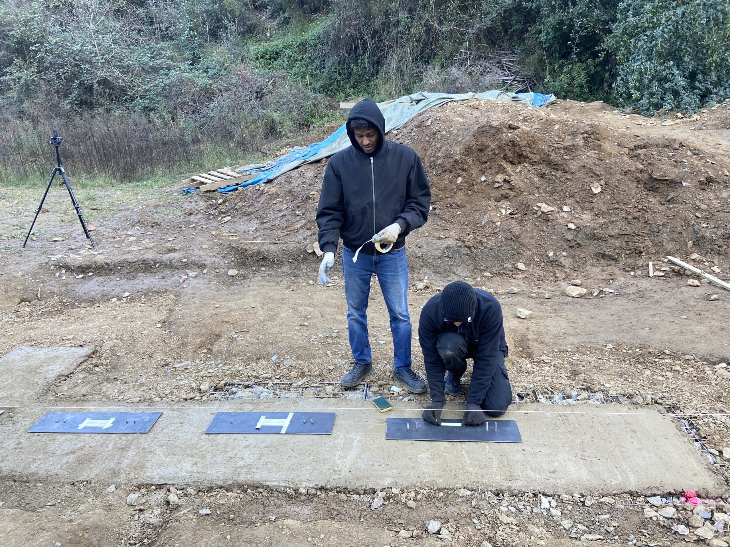
The foundational gabion system across our site consists of 1m x 1m x 50cm units, each equipped with two embedded 16mm steel cables. To address the misalignment between the gabion cables and the intended attachment points for the tensioning wall cables, a metal distribution plate was installed on top of the gabions, attached to the cables with heavy-duty u-bolts. The distribution plates were then drilled in the exact location of the cable connections and eye-bolts were secured, protected by the aforementioned PVC tube assemblies, with horizontal access holes at the bottom of the plinths. These assemblies are designed to counteract the wind lift on the roof with up to 500 kg per cable.
Construction Planning
This timeline outlines a structured plan for a 2.5-month 3D-printed wall construction project, spanning from December to mid-February. The project begins with the Design to Production phase, ensuring all necessary blueprints and models are prepared before moving into the Excavation and Gabions Placement stage, which takes place briefly in December. Site Preparation and Plinth construction follows, extending into January, creating a stable foundation for the 3D printing process.
The Wall Print phase starts in January and continues into February, signifying the primary construction phase using 3D printing technology. Once the printing is completed, Wall Finishing begins in February, adding refinement and durability to the structure. Concurrently, Roof Carpentry and Site Closing are executed, ensuring the structure is weatherproof and ready for final documentation. The plan concludes with a Documentation phase, likely for record-keeping, analysis, and potential future improvements. The timeline also accounts for a winter break, indicating a pause in construction activities.
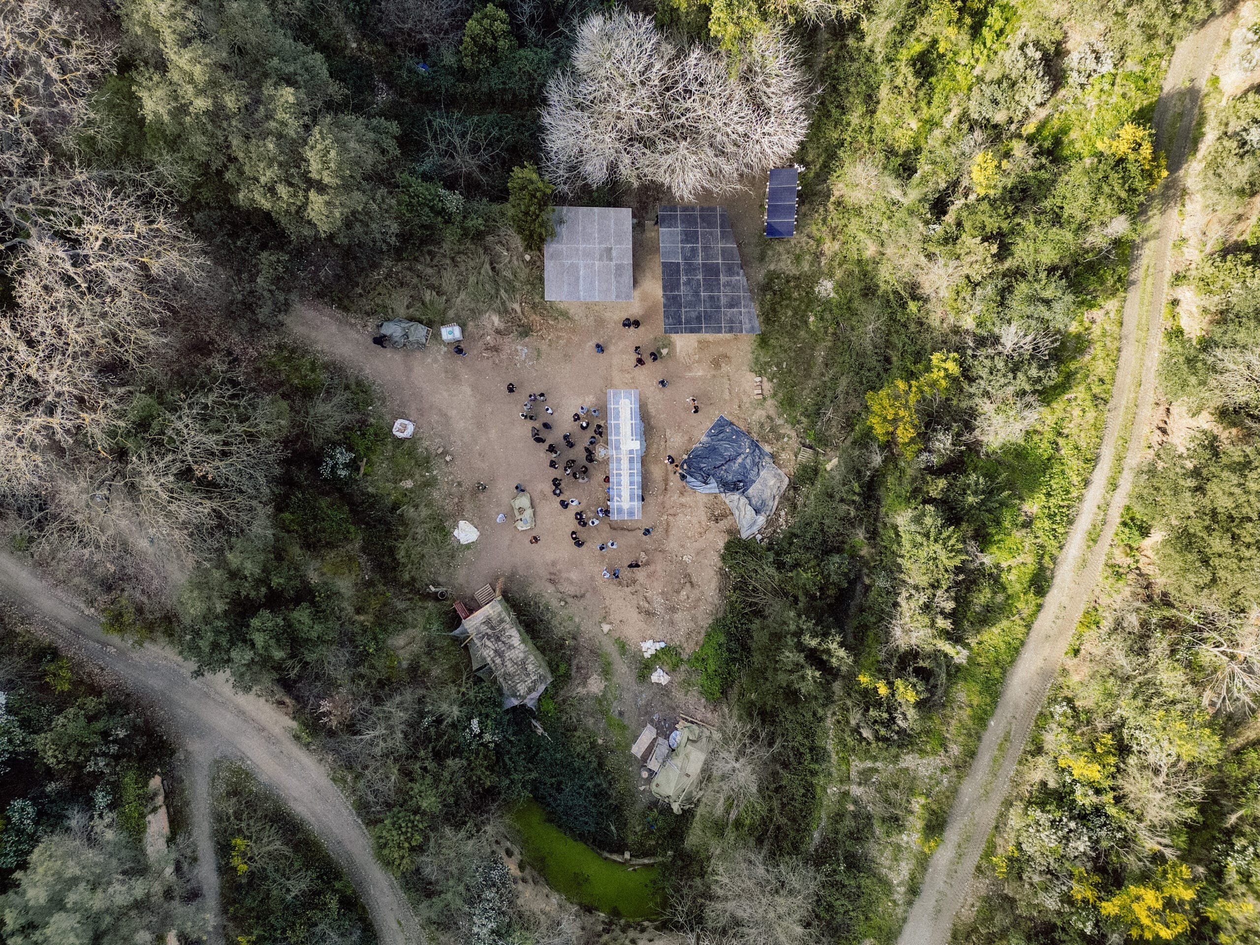
Site plan organisation
1:1 Scale
A. Site organisation
Site Preparation
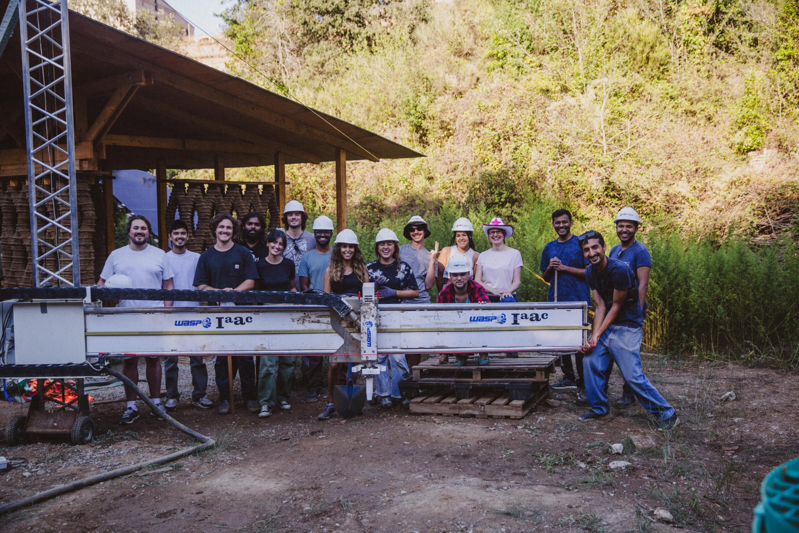
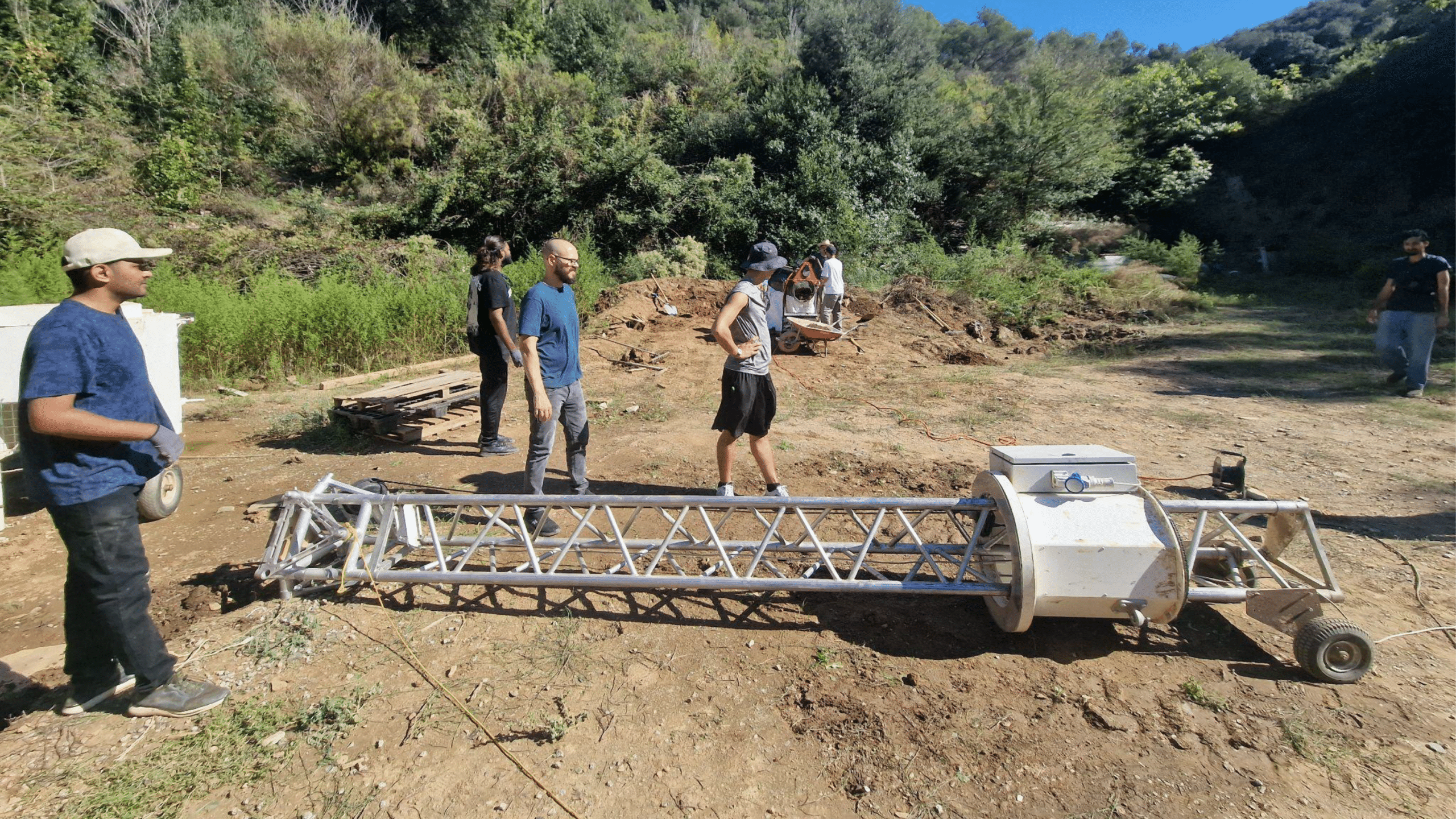
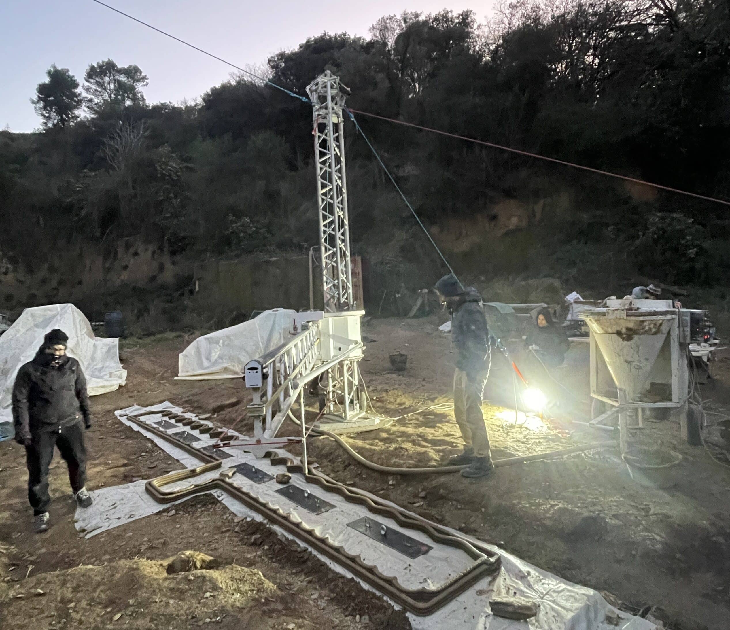
Crane setup and Assembly
Tarp Setup
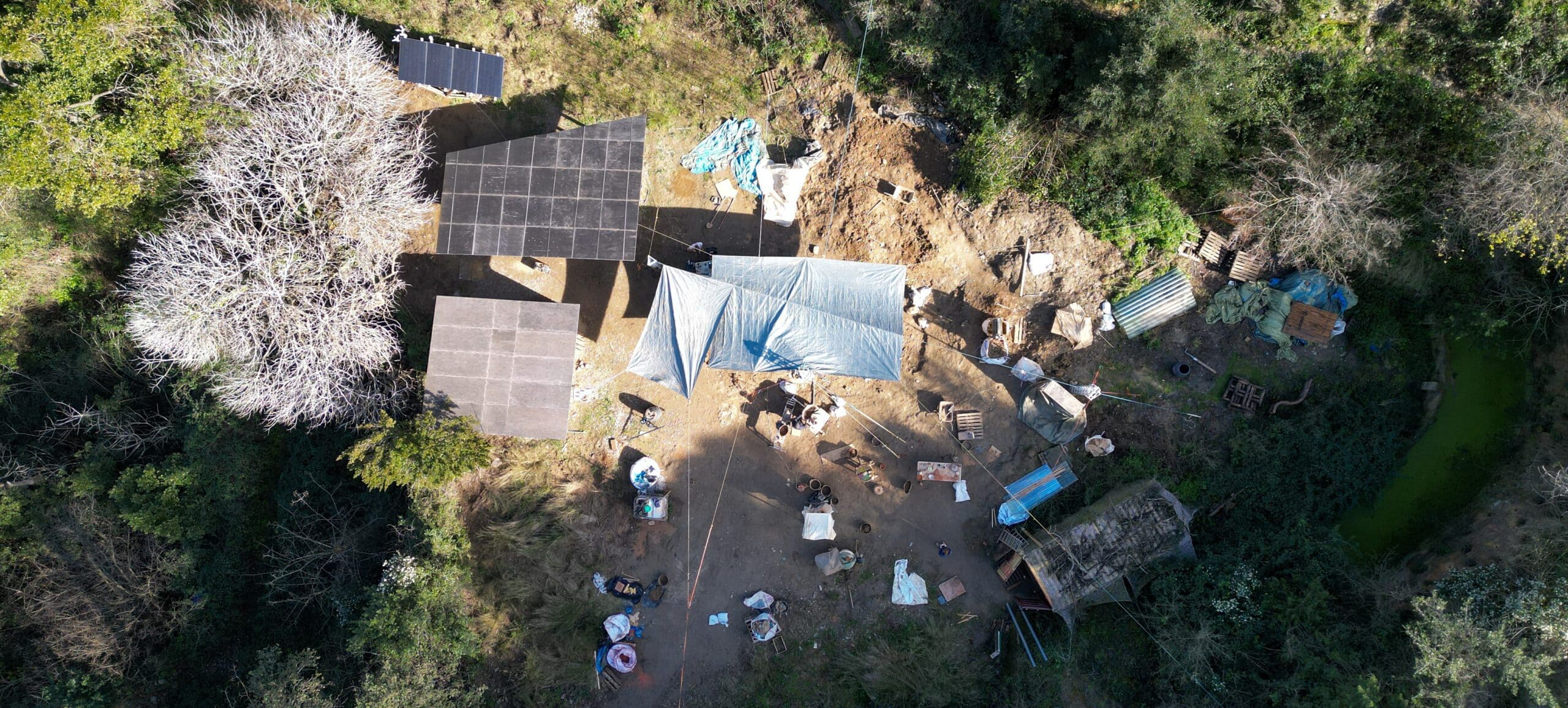
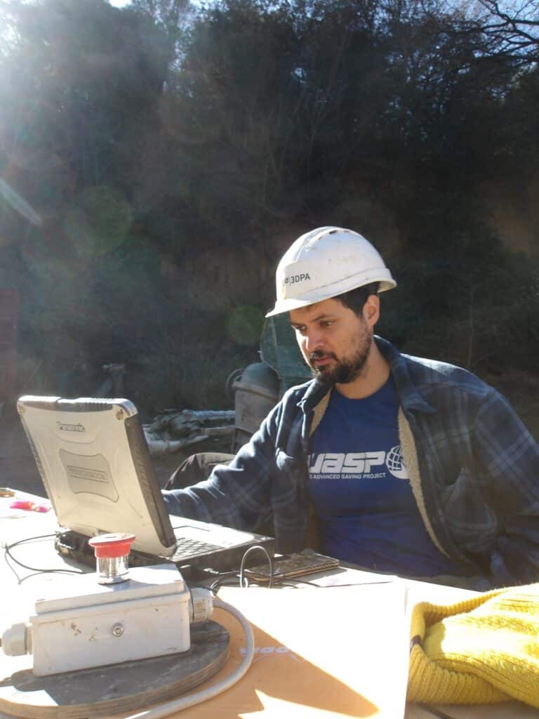
Computer station
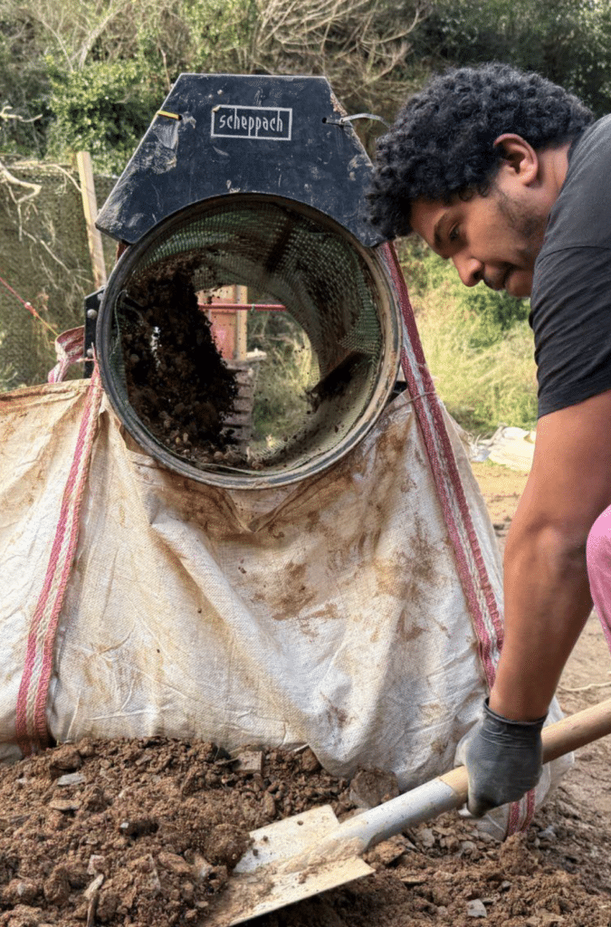
Sifting station
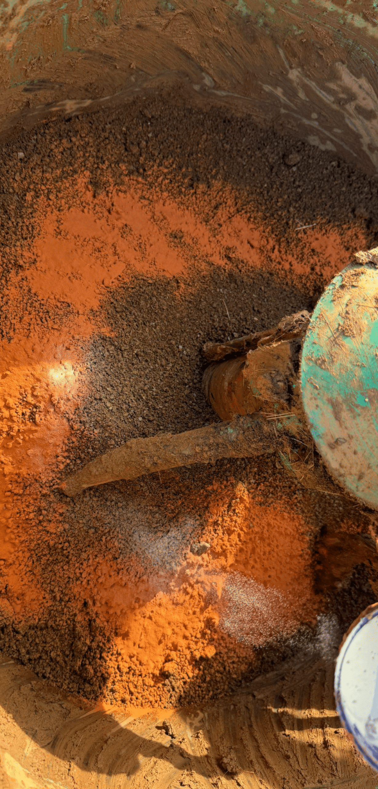
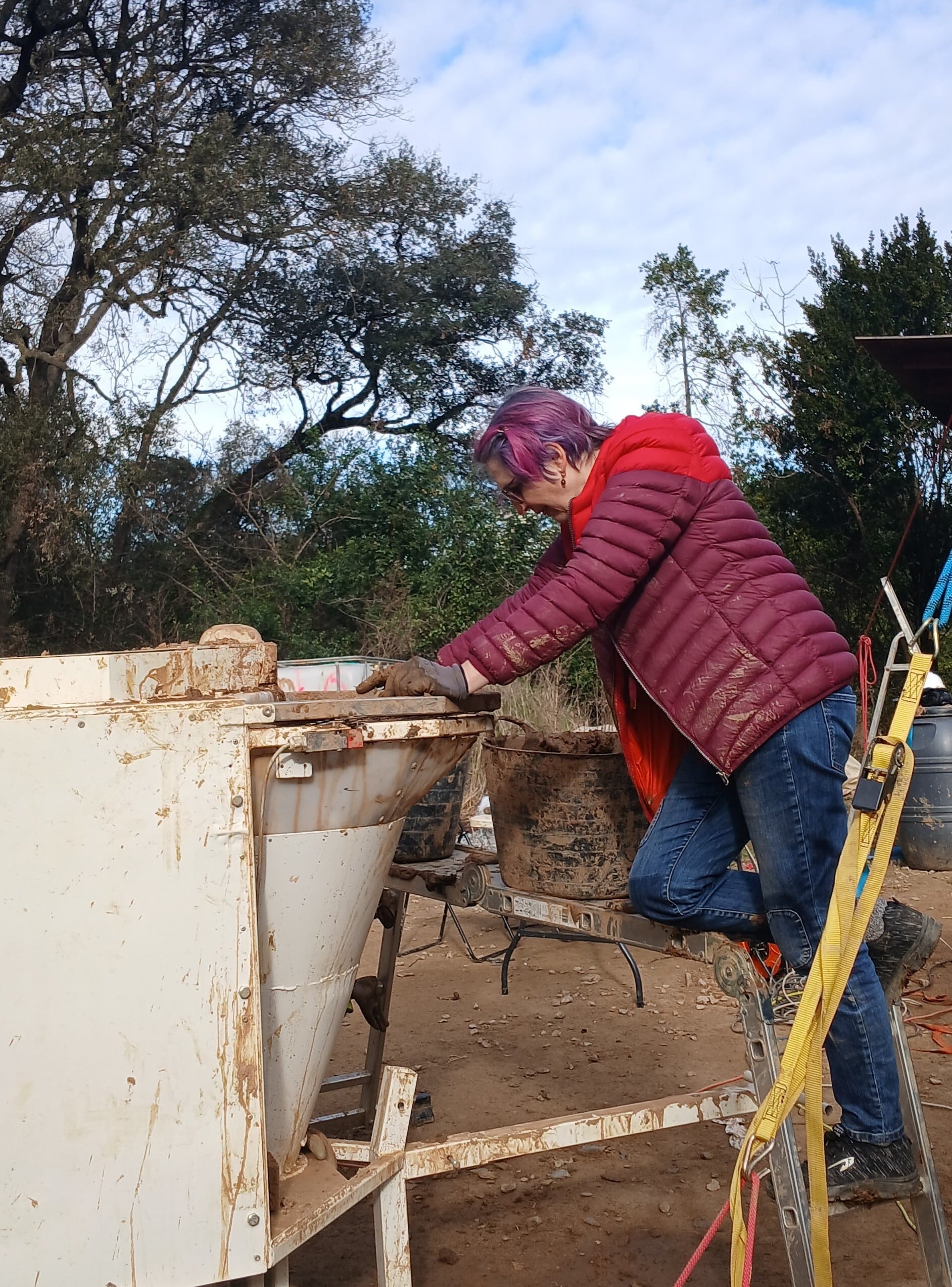
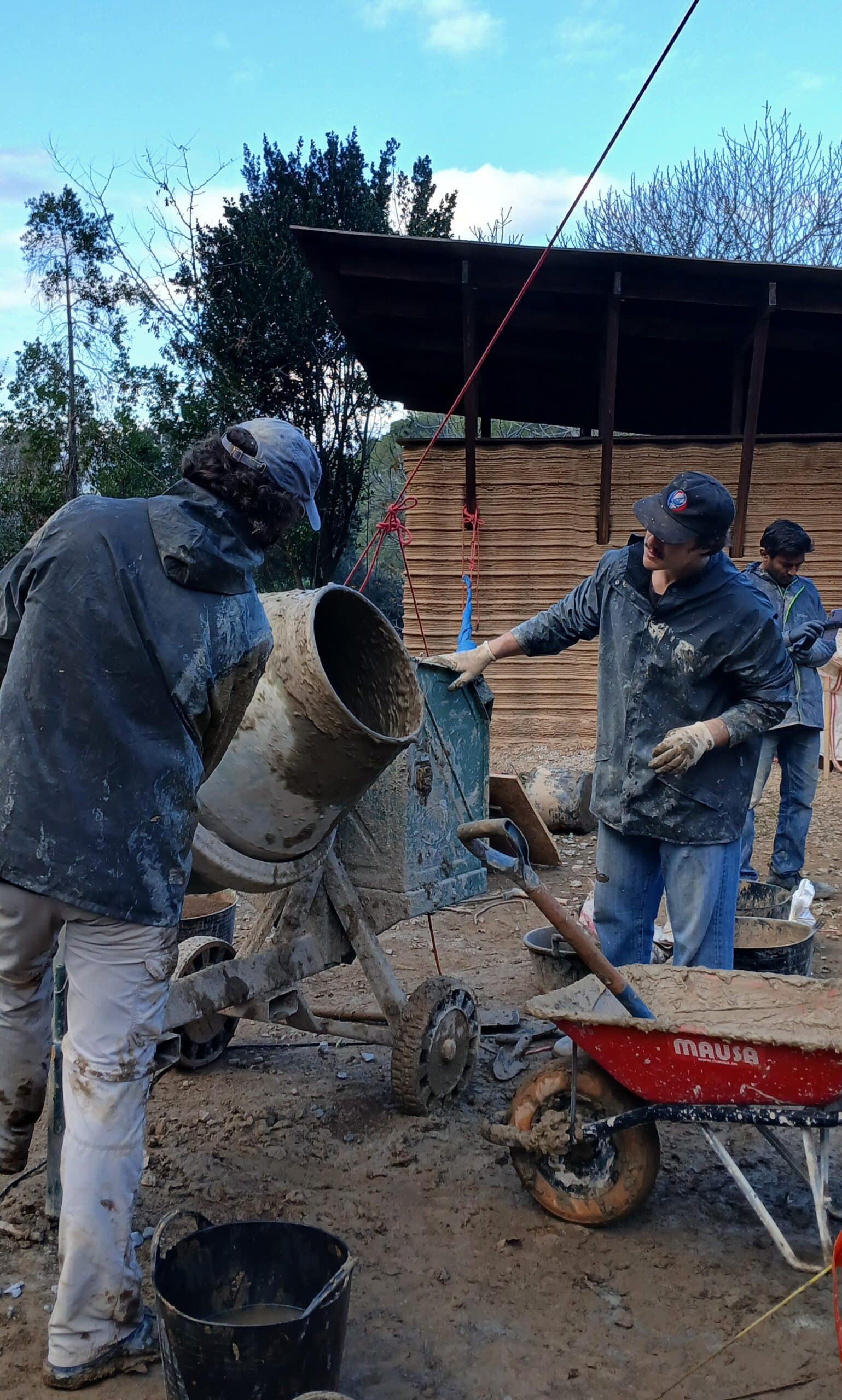
Mixing station
Pumping station
B. Construction
Foundation excavation
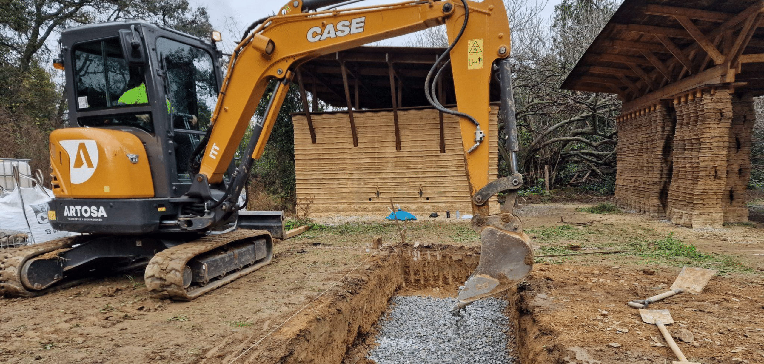
Gabion placement
Concrete mixing station
Connection of the U-bolt with Gabions
Leveling Process: Formwork, Rebar Reinforcement, and Pouring
Steel Plate Placement
Print the Plinth Formwork
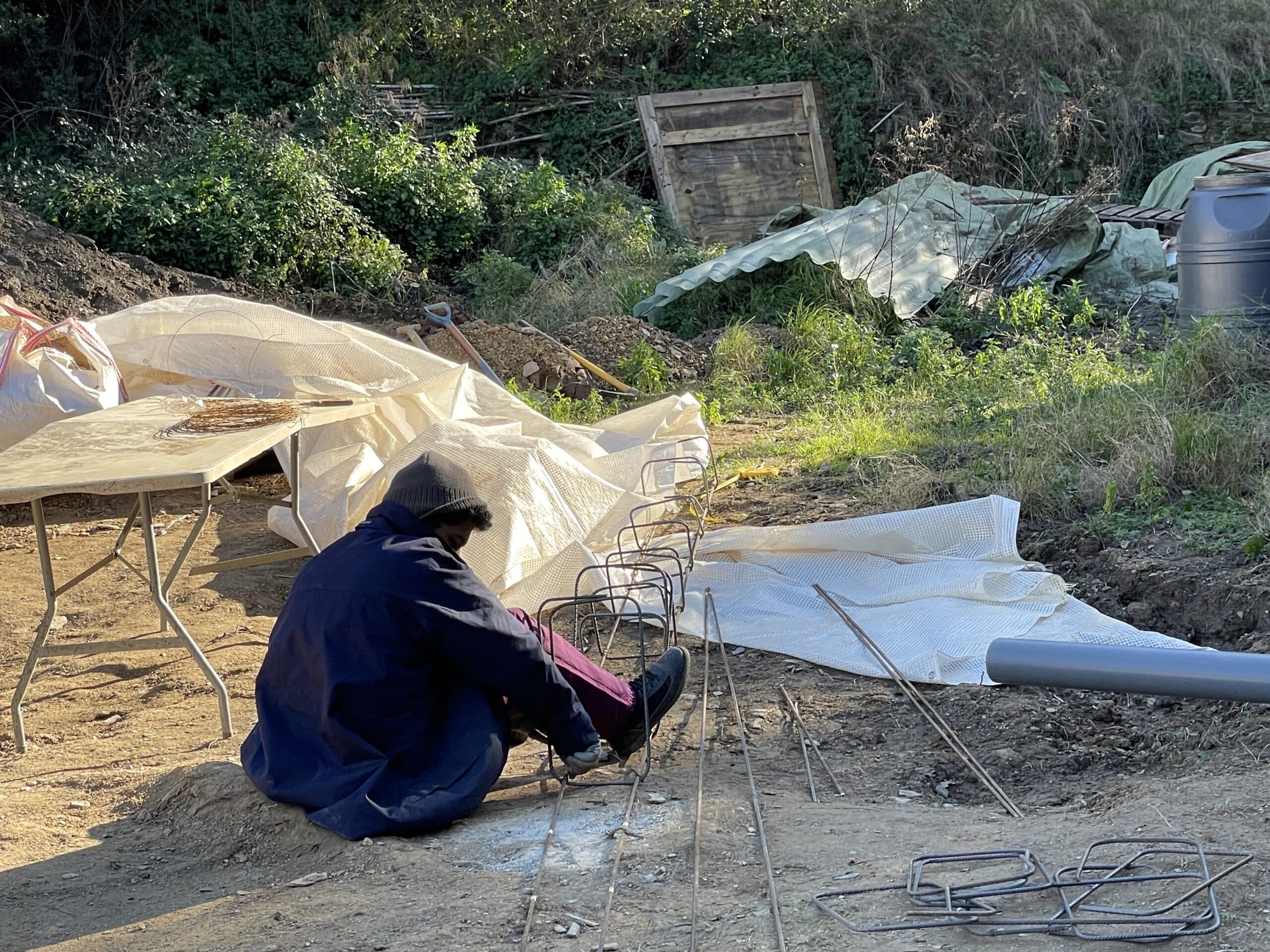
Prepare the Steel Reinforcement Framework
Prefabricated Protective Cable Conduits
Leveling the Plinth
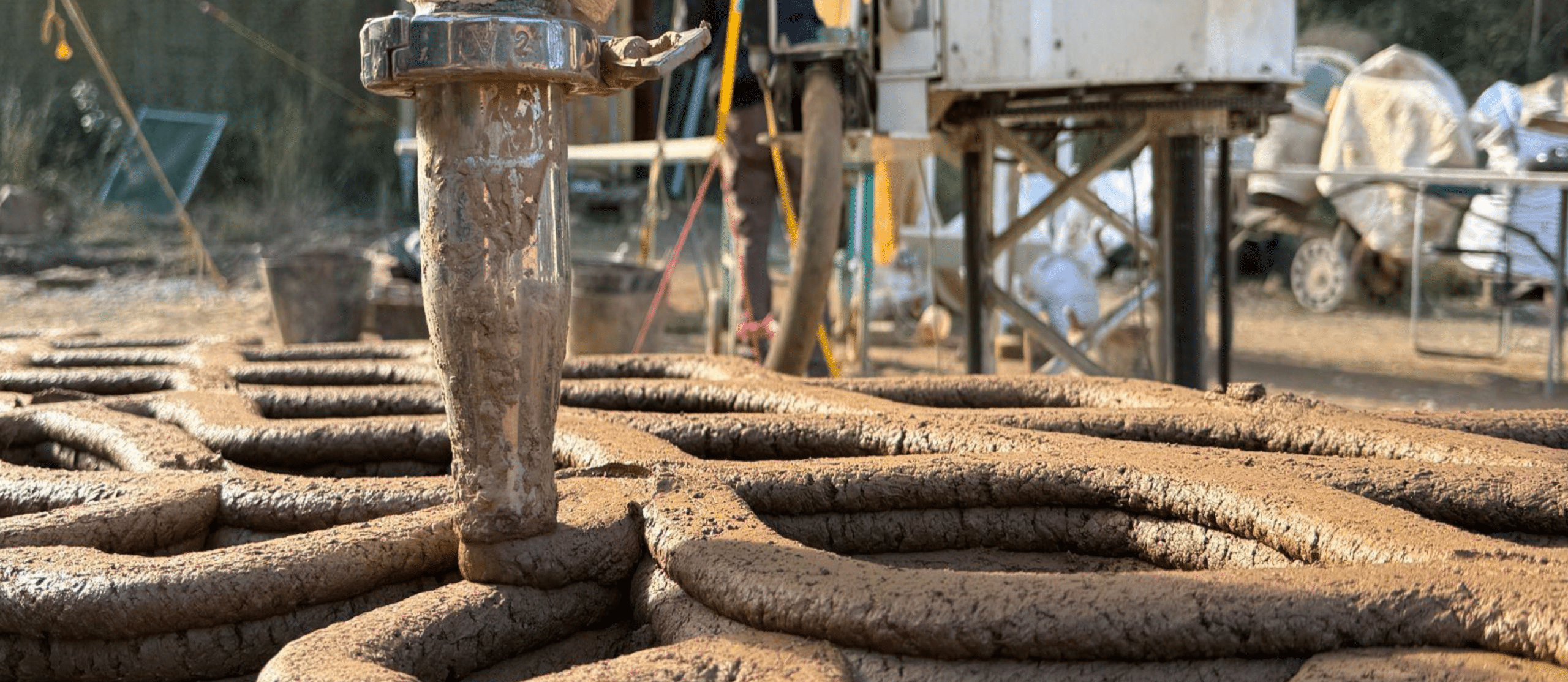
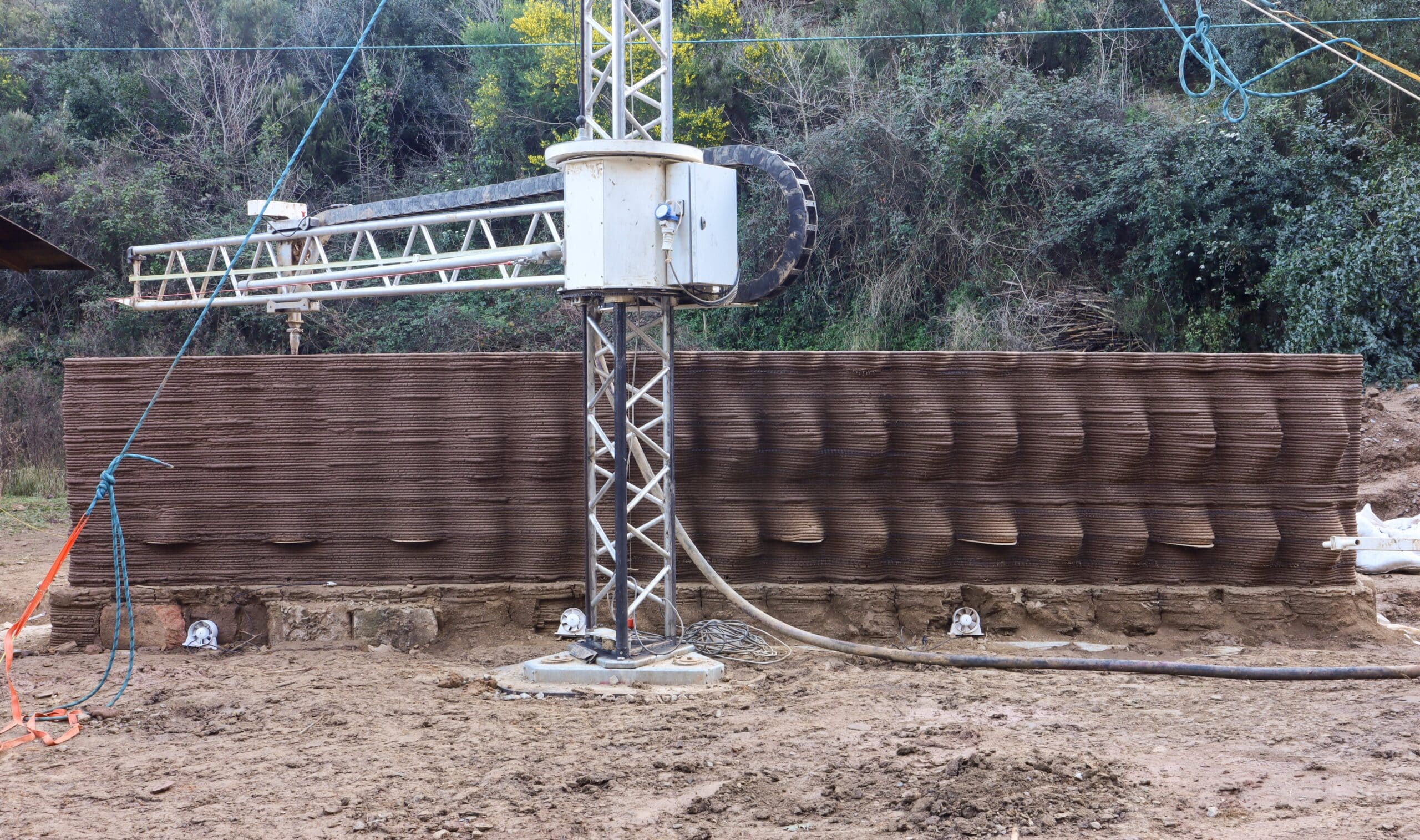
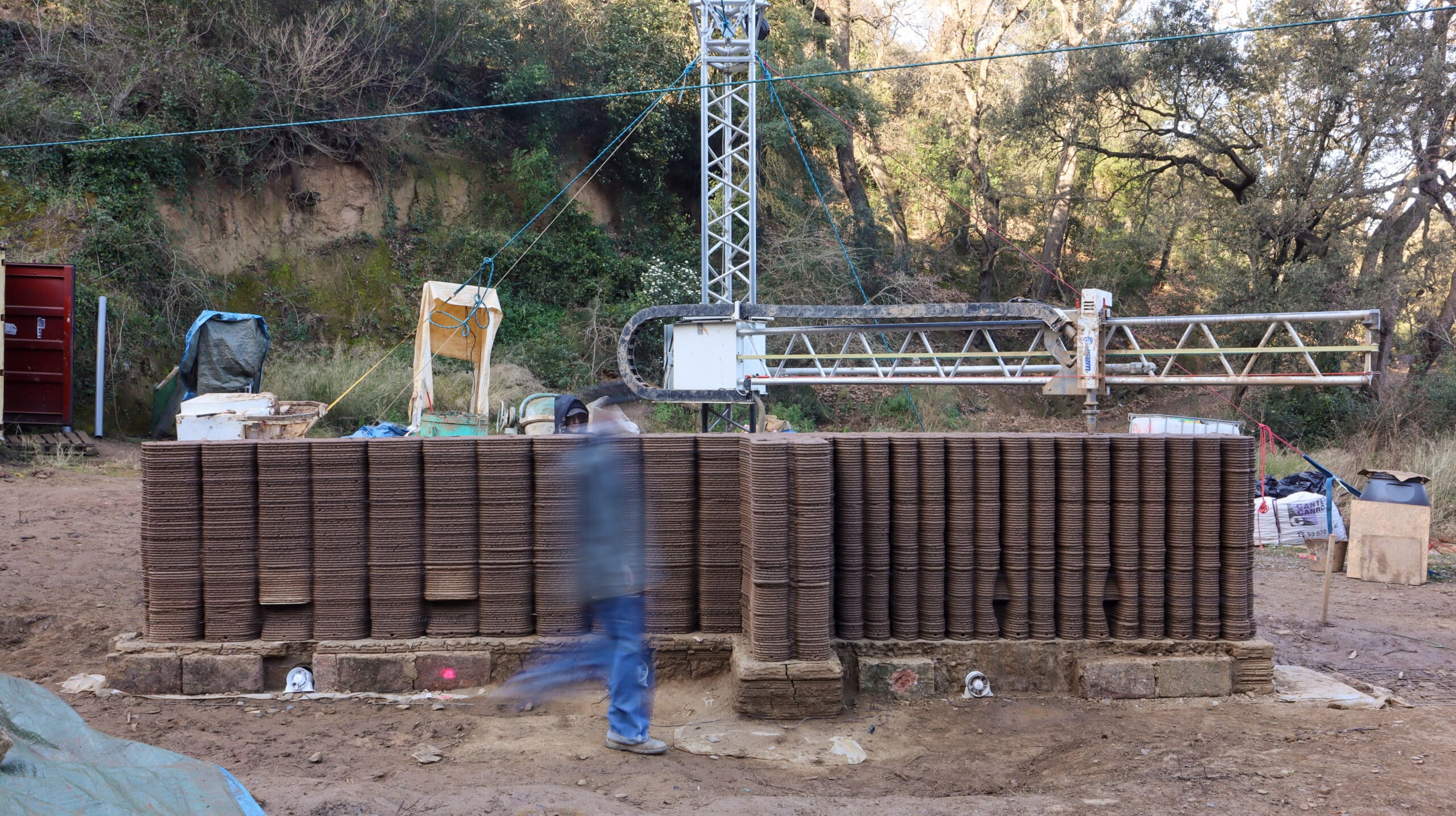
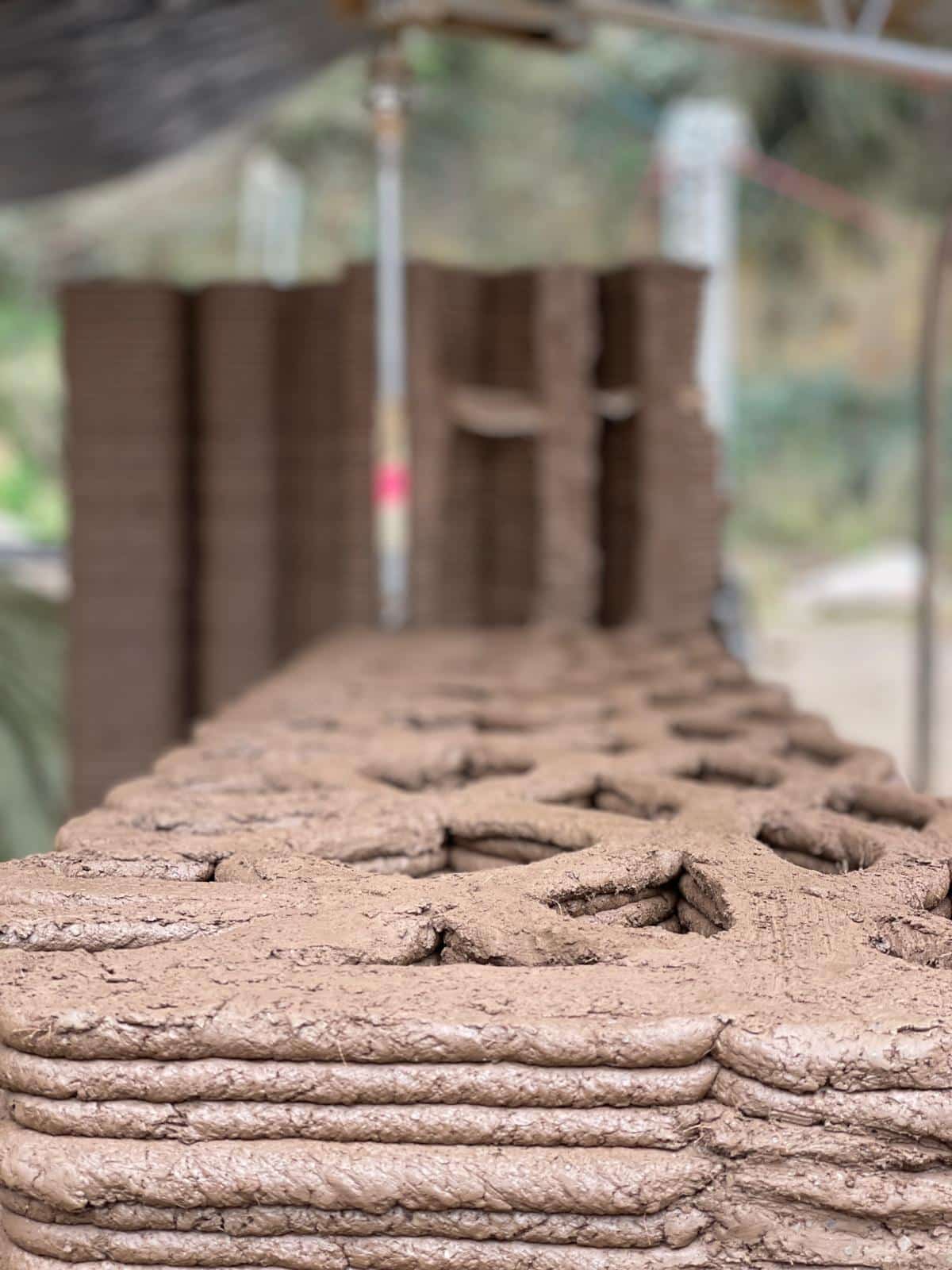
Wall Printing
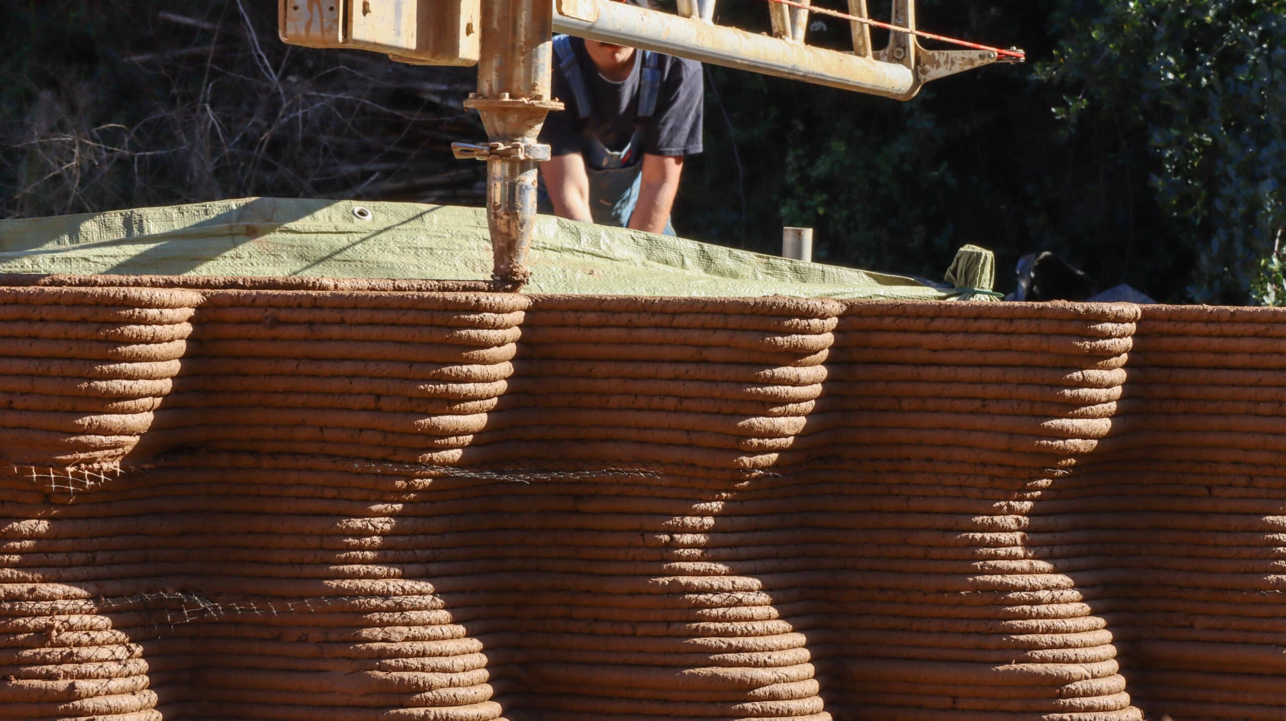
Nozzle
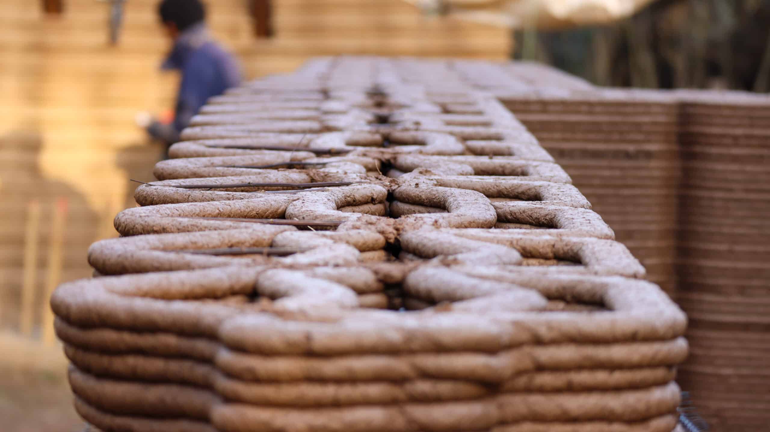
The nozzle operator must monitor the quality of the extrusion. If the earth is too dry, cracks will appear on the surface; if it’s too wet, it becomes too liquid and hard to shape. The pump should be adjusted based on the operator’s observations, adding more water or drier material as needed. At the same time, the nozzle operator must communicate with the computer operator to control the crane’s speed and the extrusion rate.
Mesh and Panel Inserts
Sticker Placement
Printing l Outdoor Facade
Printing l Indoor Facade
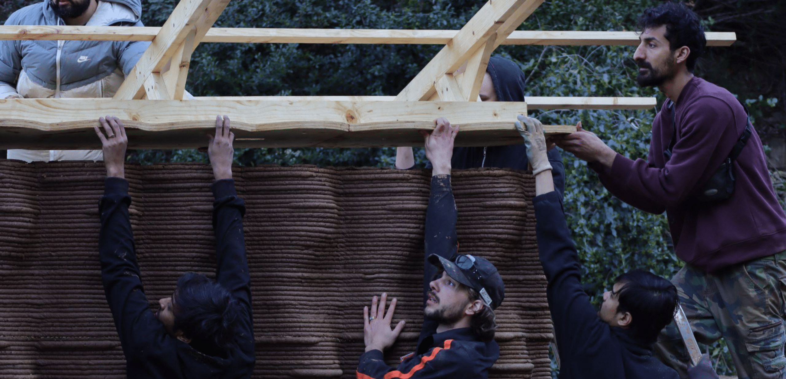
Assembly of the Roof system and anchoring the tension wire
Placement of the Roof Structure
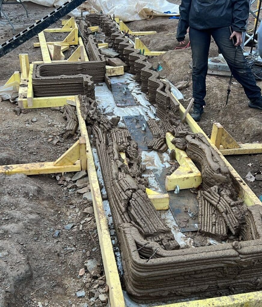
Construction Challenges and Adjustments
Throughout the construction process, we encountered three major failures that required quick adaptation. The first issue arose when harsh climate conditions caused the plinth to break. To resolve this, we reinforced the base by using bricks as formwork, stabilizing the foundation.
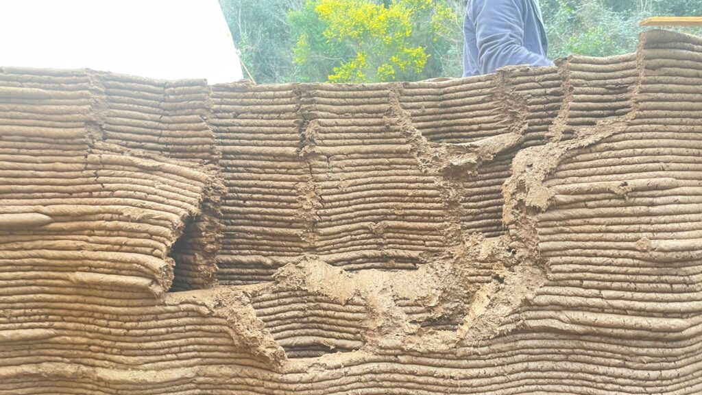
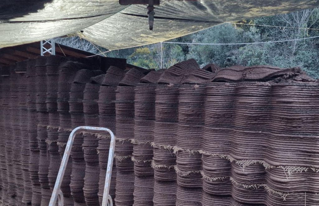
The second failure occurred due to improper tarp covering, allowing exposure to environmental factors that weakened the north side of the wall. In response, we cleared the damaged section and reprinted the affected area.
The final challenge occurred on the south side, where rapid drying caused the layers to slip leftward, requiring immediate intervention.
Adjustments
C. Final Prototype