Solis Centrum Overview
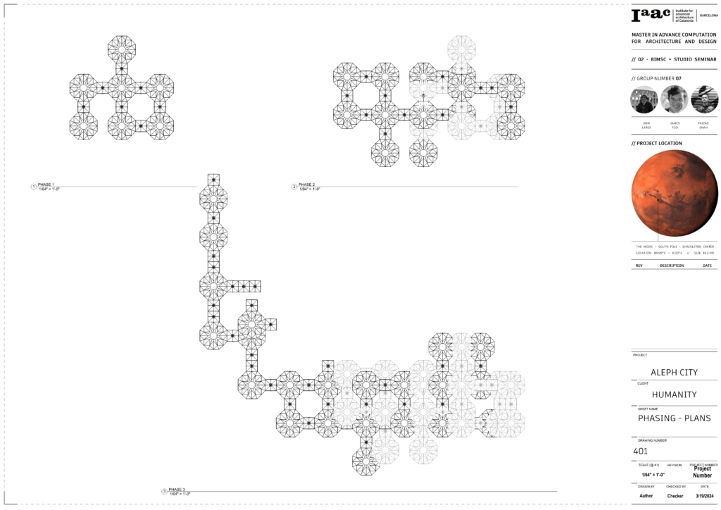
Solis Centrum is a project for the BIMSC Studio class within the 2023/24 MaCAD program. This project aims to represent the solar center of the Aleph City community, a conceptual community on Mars located on the Valles Marines.

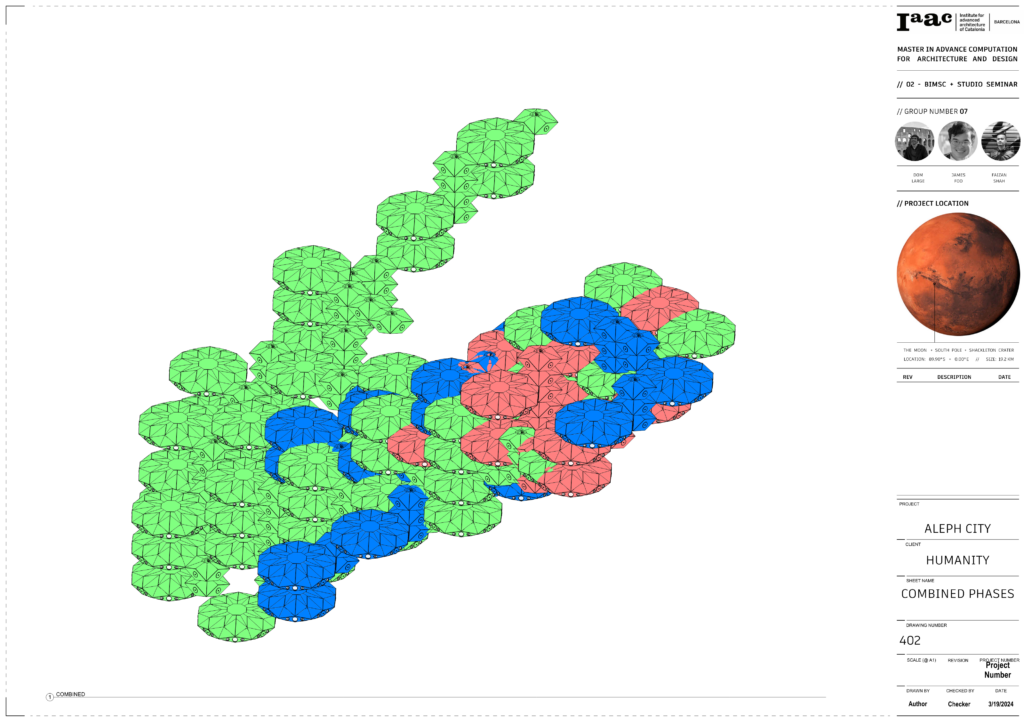
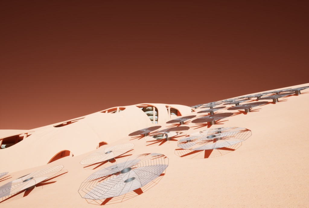
By providing residential, recreational, and energy harvesting facilities, Solis Centrum can not only provide places for occupants to live and work toward our goal of providing power to Aleph, but also provide opportunities for inhabitants to enjoy and make the most of their time within Aleph. By using an elevational approach, Solis Centrum rests atop the mountain overlooking the Valles Marines. Using a folding construction method and inflatable habitat interiors, two sizes of units are easily aggregated along the hillside and then partially covered by a series of protective shells to block out radiation. Outside of the shells are a series of solar collection units to power Solis Centrum and Aleph City.
Location
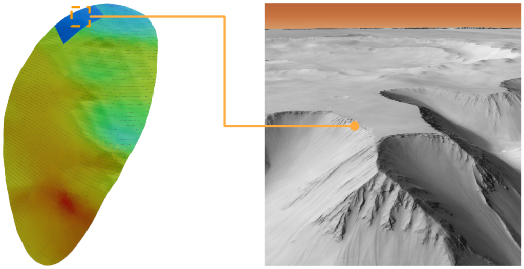
Solis Centrum is located along the northern mountain top of the Aleph City Macro Site. This location allows for maximized view of the valley below, as well as maximized solar gain for the energy harvesting process.
Design Process
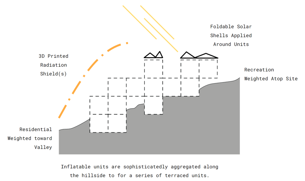
The design process for Solis Centrum is represented by the Parti Diagram shown above. Following an elevational approach, Solis Centrum is comprised of repeatable modules that have recreational units weighted toward the top of the site, while residential is down below. Connection units are populated between recreation and residential spaces with foldable solar collection modules placed in surrounding areas. Finally, a regolith shell is placed over a cluster of units for protection from radiation.
Design Iterations
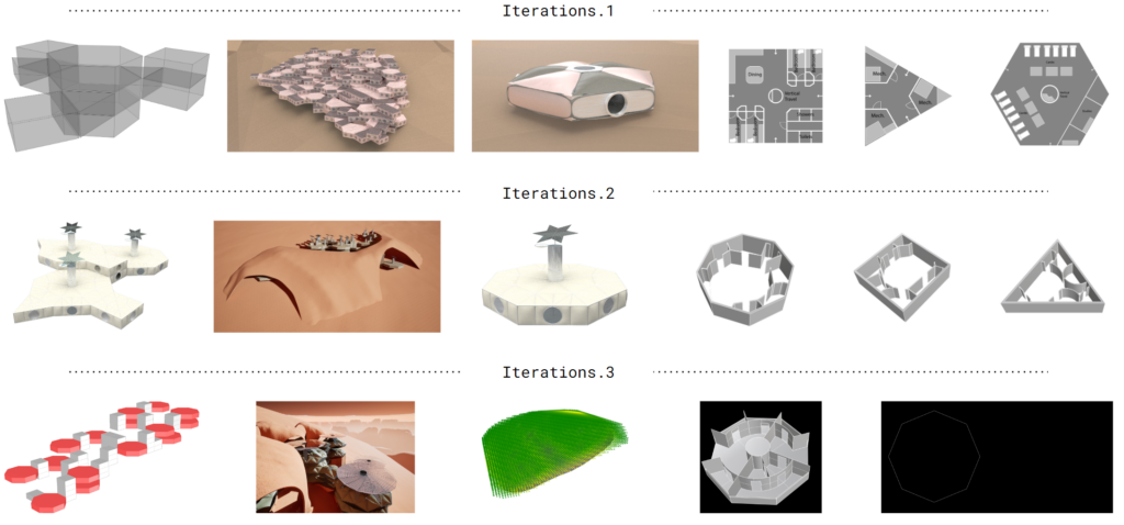
The overall form and design of the project changed and evolved greatly as it was developed. The images above show snapshots of different iterations.
Rhino Geometry
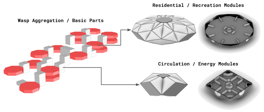
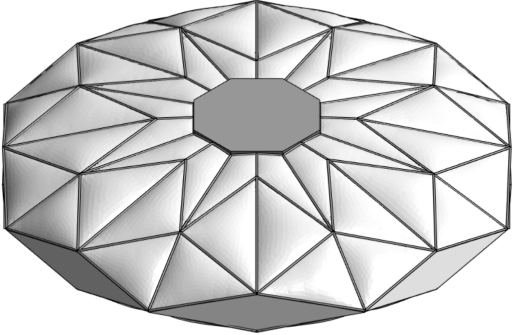
The overall aggregation was created utilizing the wasp plugin in grasshopper. The initial aggregation consists of based extruded octagons and squares to allow for rapid iteration through different options. Simultaneously, another grasshopper script was developed to create a more detailed version of each unit.
Interiors
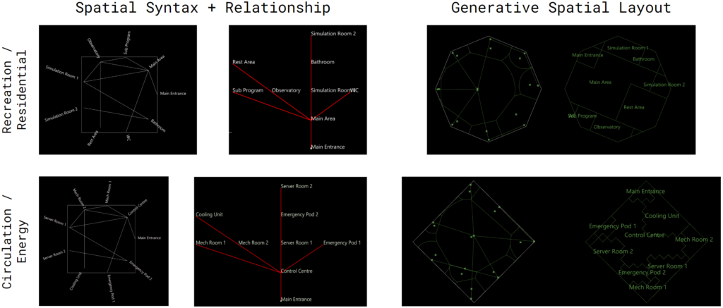
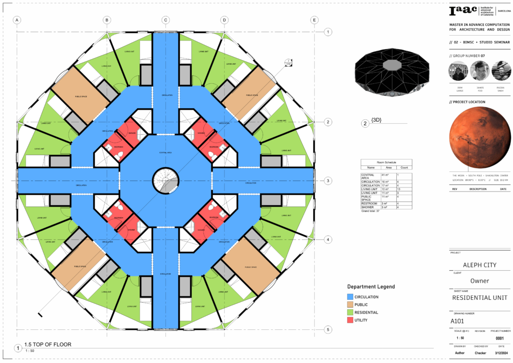
Initial conceptual design for the interior spaces was done using a machine learning model. Each type of space was given a hierarchy value which the algorithm used to create an efficient space for the required program.
Workflow
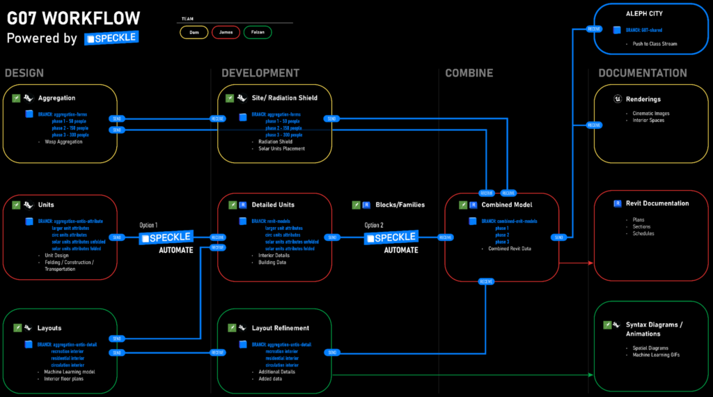
Speckle was the primary vessel of information between the designers. Each designer took on a different scale of the project, with Dom focusing on the large-scale overall aggregation and site, James focusing on the medium-scale unit geometry, and Faizan dealing with the small-scale interior layouts. Speckle’s ability to manage and curate data structures were vital in our pipeline of information from Rhino to Revit.
Rhino to Speckle
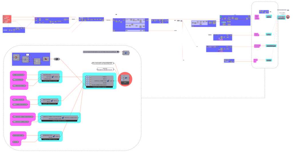
Shown above is the grasshopper definition responsible for the creating the unit geometry. After the script is run, the final data is packaged in a highly specific way to facilitate its use in Rhino.inside.
Speckle to Revit
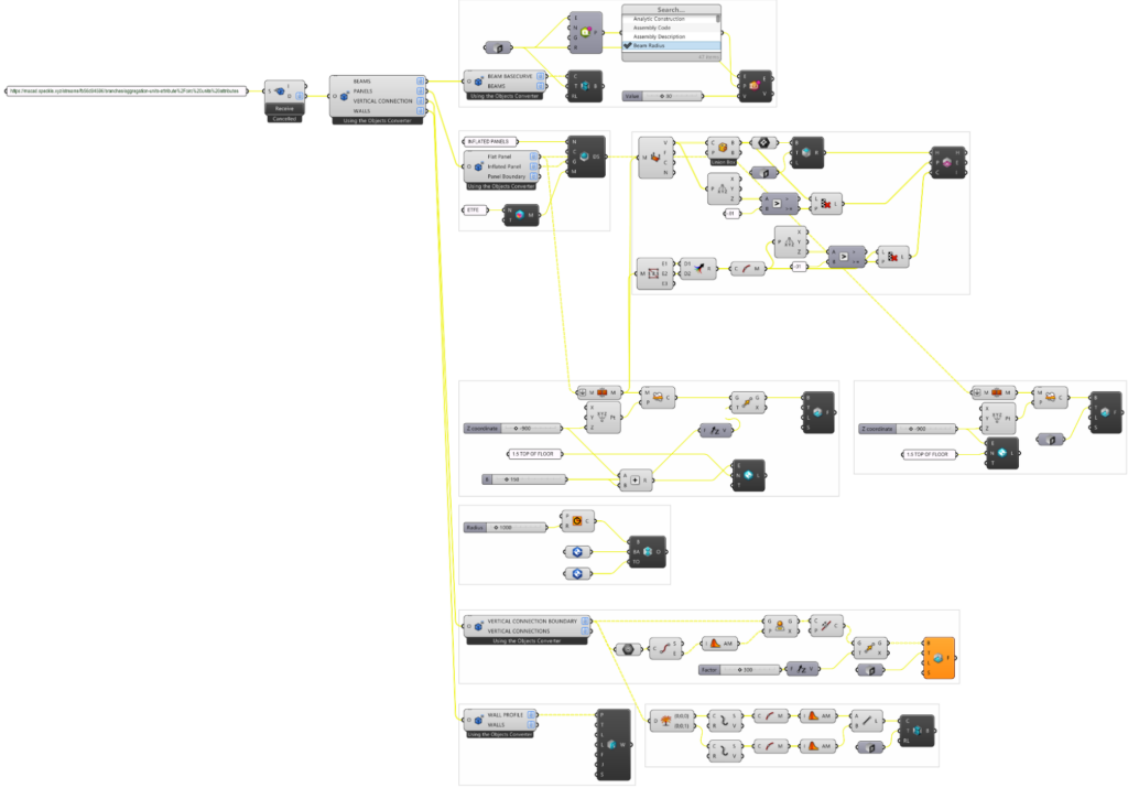
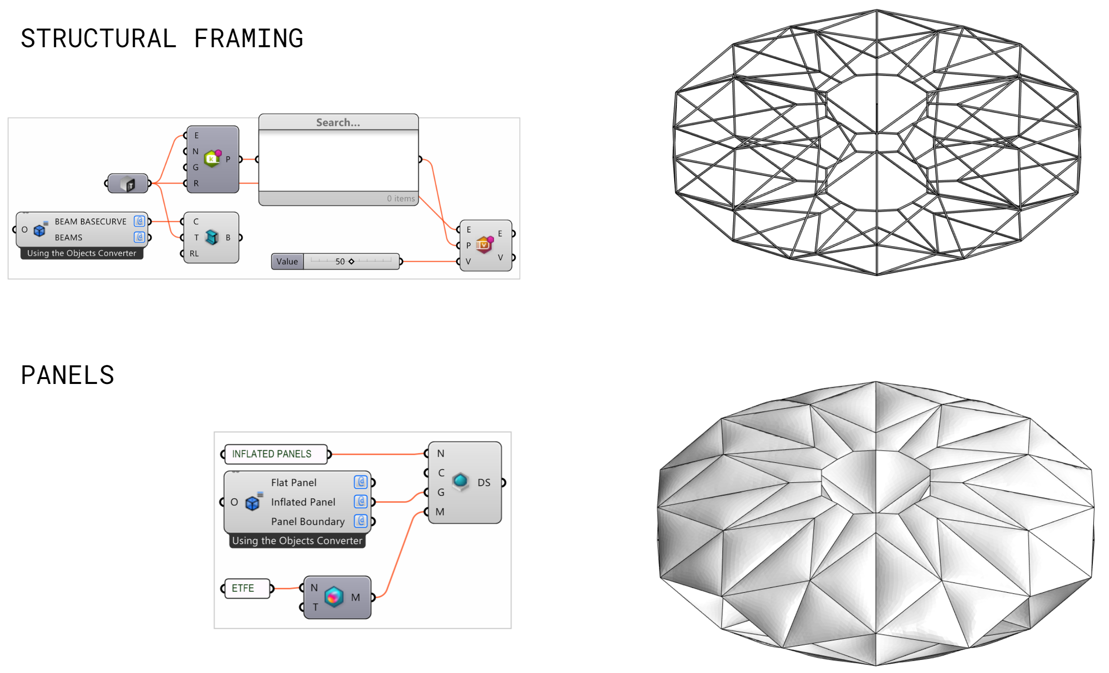
This script shows the process of the packaged data being deconstructed and used to create the native Revit geometry. More detailed versions of the structural framing and panels workflow are depicted below:
Structural Framing & Connections:
BIM Integration
Detailing
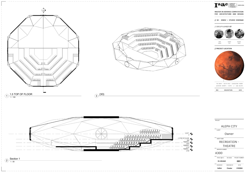
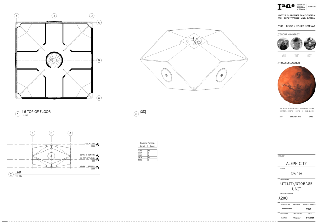
Once the exterior enclosure of the unit is successfully imported to Revit, additional details are added using native such as walls, stairs, and doors. Each unit has a specialized interior based on it programmatic role within the overall design.
Custom Families
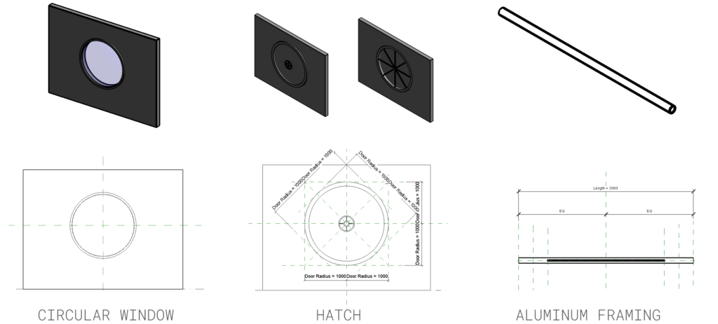
To help facilitate the detailing process, a few custom families were developed. Each being parametric to allow for ease of change and better integration of Rhino.inside.
Filtering
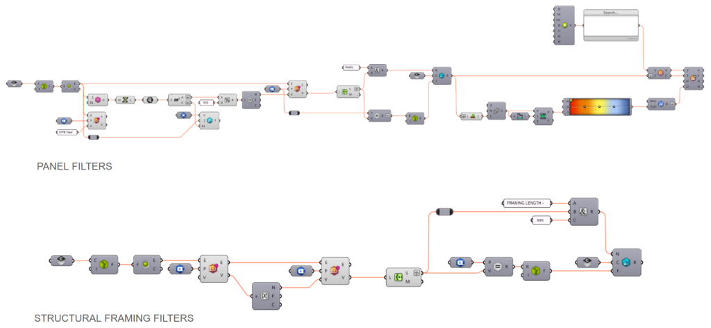
Rhino.Inside was also used to automatically create filters based on geometric data for each building component, such as length or area. These filters were then applied to the view still using Rhino.inside, fully automating the process.
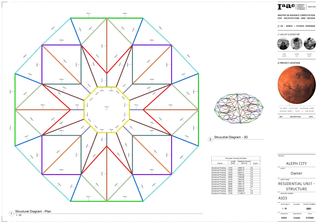
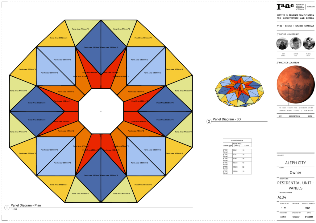
Link Placing
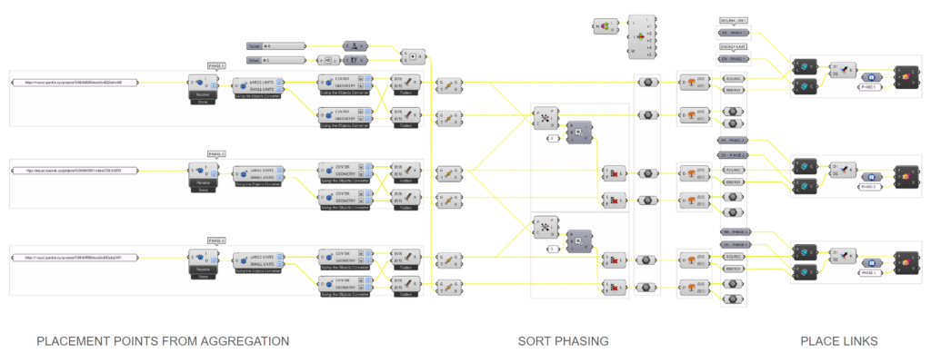
Finally, once all individual unit Revit files were created, they were then linked into the overall site model. The location and phasing data was received from a speckle stream and then used to clone the unit across the project and assign it to the correct phasing, creating a detailed version of the overall aggregation.
