
Aim
Develop prefabricated and post-processed 3D printed clay modules for self-supporting surfaces
Context
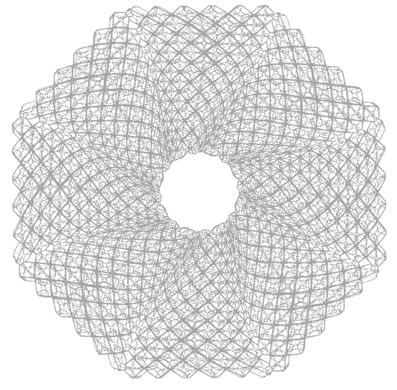
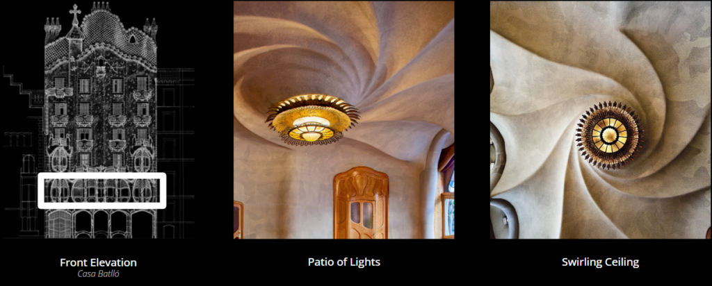
What could we learn from a study of Gaudi’s ceiling in Casa Batllo? This was the jumping off point of this studio. Responding to a requirement to choose an element of an Art Nouveau/Modernisme building – an opening, arch, or surface – and recreate it using clay, timber, or cork, we chose to remake the ceiling of the Patio of Lights using 3D printed clay.
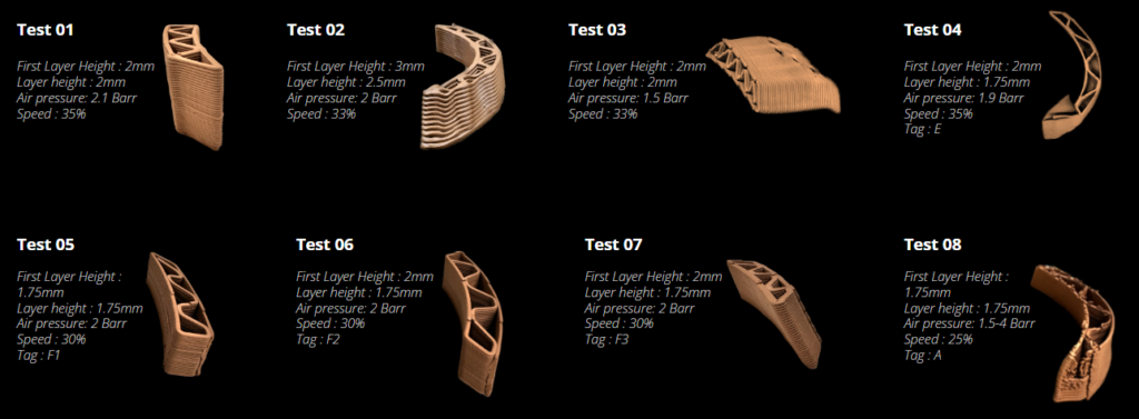
We began by developing our intuition around 3D printed clay with several test pieces. The clay printer end effector was mounted on an ABB140 robot, used a screw driven by a stepper motor to ensure a steady flow of clay, and was fed by a pneumatic cartridge loaded with clay.

For the project we used Sio-2 PF engineered clay. We added water and kneaded the clay by hand until a smooth consistency was obtained that would allow it to flow through the extruder. Tests for print spacing and infill density were conducted to develop our understanding of the material and process requirements.
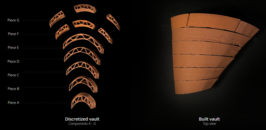
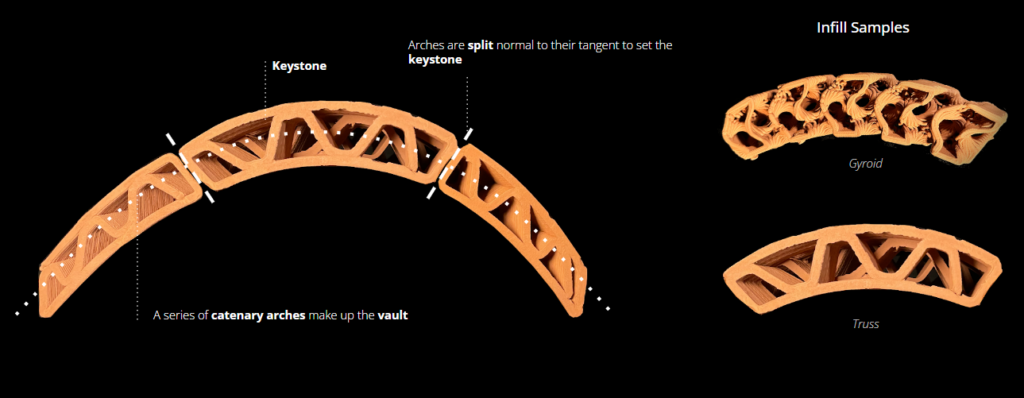
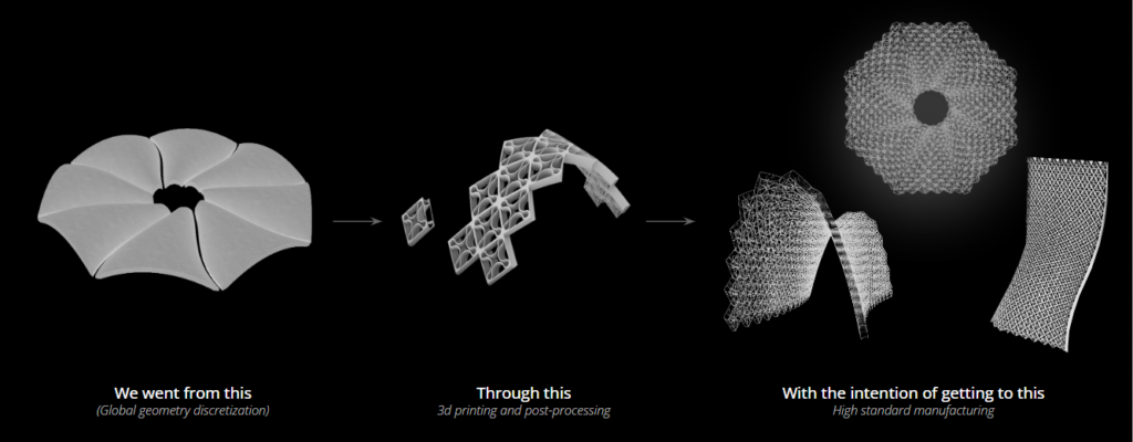
Concurrently with material and process explorations, we worked to discretize Gaudi’s ceiling. The ridges between the eight petals of the ceiling made for obvious divisions. The petals were then broken down into smaller components, the size of which was determined by the interior of the kiln at IaaC.

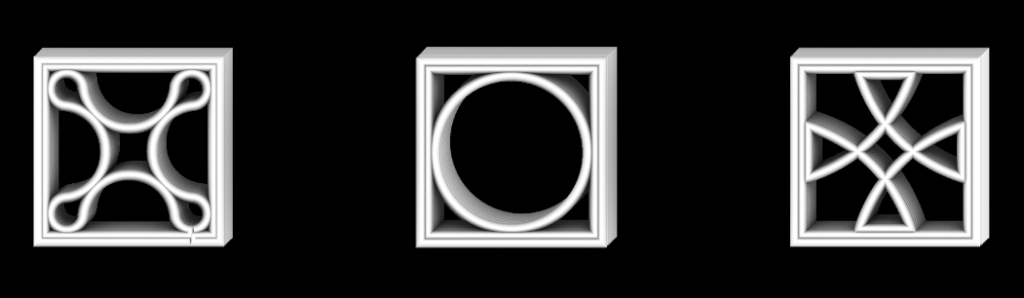
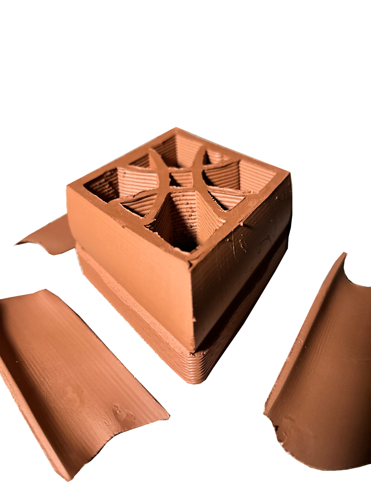
We printed the components, exploring along the way two types of infill. The first was a truss-type, and the other was a gyroid – a type of shape that can generally only be produced through additive manufacturing. While promising, the gyroid concept was abandoned due to its added complexity which was out of the scope of this project, however it is worth exploring further in the future.
As we printed and assembled the components from this initial exploration it became evident that the challenges associated with 3D printing a self-supporting clay ceiling structure were manifold, and rapidly expanding. With every solution we discovered, we encountered several new challenges to be solved.
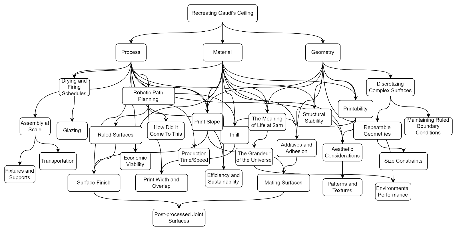
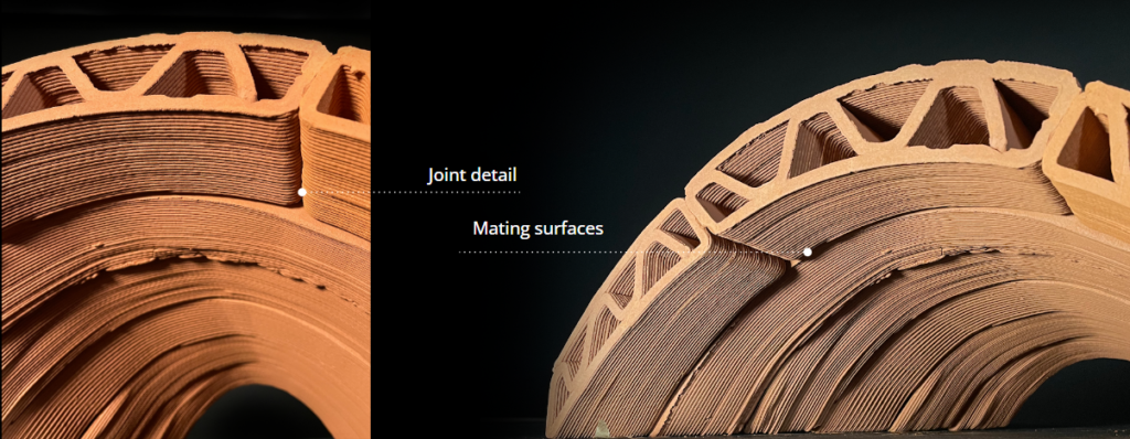
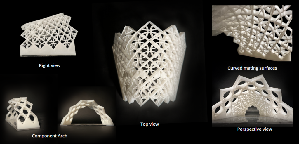
This led us to narrow in on one specific feature of the design to advance. We chose the mating surfaces between components. The reasons for this were firstly because clean mating surfaces would improve stability of the structure; and secondly because we proposed to improve the mating surfaces through post-processing, which is an area where there was relatively little existing research and where we could therefore contribute.
Design Explorations
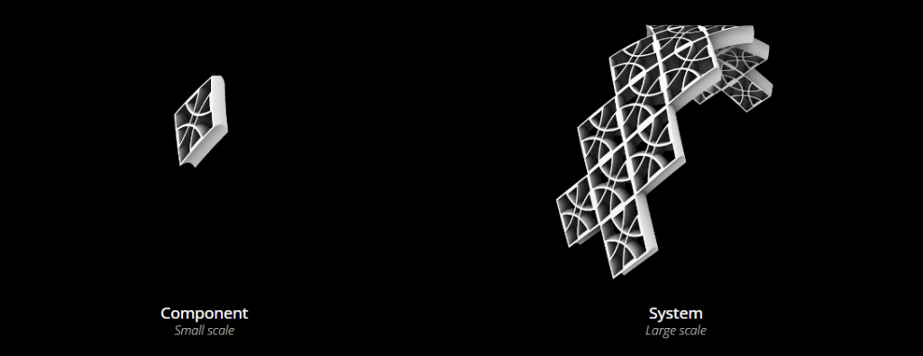
Our intent was to focus on one simple element of the complex problem, in order to hopefully apply it more broadly to global structures
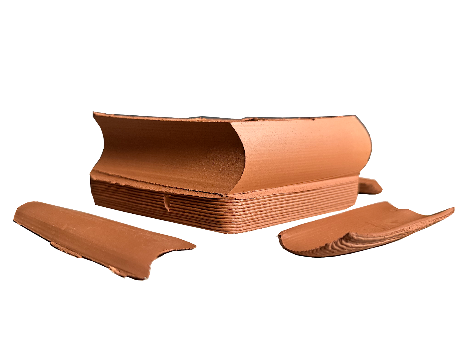
We made several tests of shapes. We picked one that was as simple and quick to print as possible. The point of this was to establish a form that worked, knowing that the infill of the shape could readily be replaced when we were ready for more advanced work. We then worked on overlaying it on various shapes in grasshopper, and also printing it in real life. We did our first cut with the robot this way too.

Process
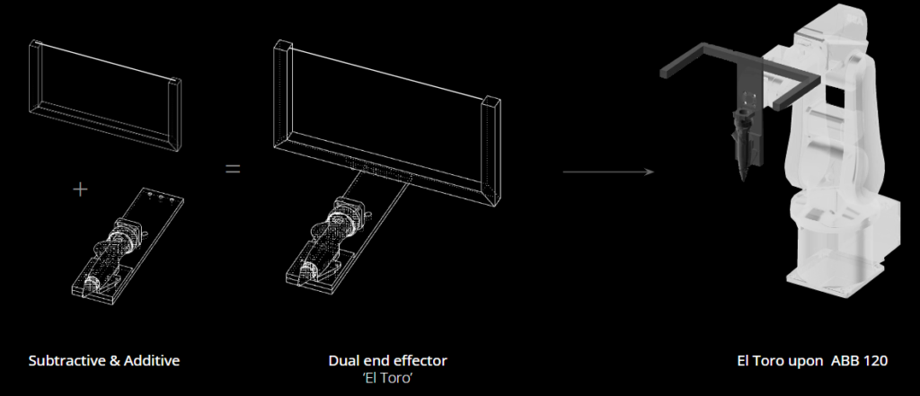
We developed a dual process end effector by attaching a wire cutter to the extruder assembly, allowing for a print and cut process.
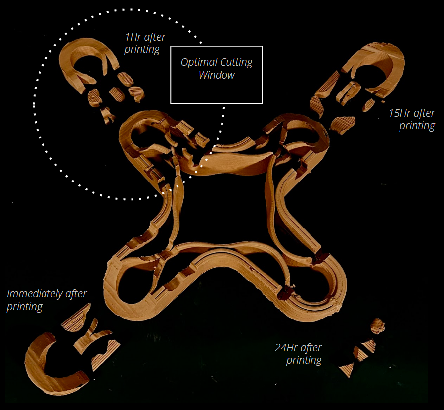
We did a test to see when the best time would be to wirecut. It turns out that around one hour is a good time. The clay is soft enough to cut, but the surface finish is better. However, it demonstrated that the clay could be cut immediately to obtain satisfactory results. Waiting too long to cut (ie, overnight) means that the clay will be too hard. Cuts could still be made in compression, but any tension applied would likely cause the piece to be deformed or moved out of place.

We applied our basic component to more complex shapes in grasshopper, to show that it was possible. We settled on a simplified vault to test the concept in real life. We printed it in PLA first, then began to print two rows of it in clay.

Our robotic process consisted of two sections: printing and cutting. The printing process followed the commonly used ABB plug-in for grasshopper. The shapes were contoured, and the contours divided into target planes for the robot. The file was checked visually for collisions before printing.

During the process, we discovered that the cutting and printing files could be run separately, so that we could refine the cuts once the printing was completed. The first cut was always the smoothest, so it was best to make only one, but we could make secondary cuts when necessary. The secondary cuts left residue on the surface, however this could be removed through multiple subsequent passes, or delicately by hand once some drying had occurred.
We also noted that we were able to repair damaged components through our process. On two separate occasions we dropped a screwdriver and the air hose from the extruder into a freshly printed component. The surface was patched, the cutting portion of the file was run, and a clean repaired surface was obtained. We believe this to be a promising capability for 3D prints, which can otherwise be ruined by surface imperfections.
Another observation was that if subsequent cuts were to be made, it would be necessary to complete the separating cuts again, since parts with their seams smoothed over were difficult to separate. With this in mind, it is possible then that the smoothing effect of the cuts may also improve the adhesion of printed layers.
Results
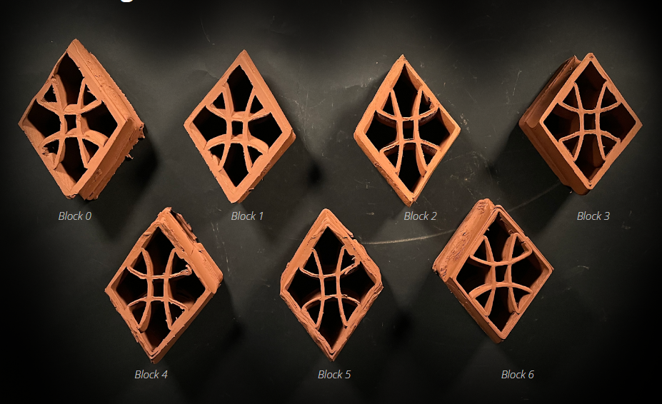
We printed 16 pieces for use in an arched segment of the test vault. Our process steadily improved throughout until a final surface finish was obtained that was very smooth.
Next Steps
From our research, we believe there are several relevant next steps
- Increased scale. While tolerance requirements are more forgiving at building scale, the surface created by Kuka sized printing is lower-resolution, and would therefore benefit from post-processing
- Alternative tools. Our end effector made use of a wire to cut. However, other tools could be used with the same logic and would have useful effects. For instance, a blade could be used after wire cutting to smooth surfaces. Or a cutting tool with a radius could be used to move beyond purely stereotomic cutting
- Unique joint surfaces. Expanding on the concept of unique, customized joint surfaces between individual components could allow assembly instructions to be built-in, and could remove the need for formwork
- Aesthetic potential. Our exploration focused on a very simple design as a proof of concept. There is a lot of room for exploration here
- Sensing and feedback systems. Some possibilities include surface mapping for improved cutting accuracy, ambient condition monitoring for print consistency, and error tracking.
