
Abstract
Architectural history contains numerous examples of vaulted structures built using a variety of design techniques and a range of materials, to serve or host different functions. One recurring function is the role of the vault as a roofing element, in part or whole.
Additive manufacturing/3d printing as a new method of construction has been used successfully to construct self-supported load-bearing elements like walls and columns using concrete and clay extrusions. However, with gravity as a limiting factor, the construction of self-supporting horizontal-spanning structures such as roofs or slabs have not quite received the gains of this new technology. The question therefore looms. How can extrudable clay be used within the realms of additive manufacturing/ 3D printing to contribute to the construction of vaulted self-supporting structures that can satisfy the 5th facade requirements?
Background
Clay/earth as a material for construction has been used in various forms. It is known to perform well in compression. Brick makers have trusted this material to make strong building blocks that easily rival natural stone in building structures that are self-supporting such as vaults. Rammed earth walls also take advantage of earth’s compressive strength.
However, 3D printing with clay requires the material to be in its plastic state to allow for extrusion. In this plastic state, clay is considered malleable, workable and significantly weaker under compression than in its dry state. Vernacular architecture contains numerous instances of use of clay in its plastic/wet-state simply as mass infills to walls that already have a structural support system in place. The wattle and daub technique is one such example. 3D printing seeks to capitalize on the workability of this material while offering a way to execute computational design solutions that allow clay to be used intelligently in architecture and construction to tackle traditional (and novel) architectural and structural challenges.
Keeping in the context of vault construction, Our research attempts to isolate the 5th facade and explore the possibilities of designing for the extrusion and prototyping of 3D printed rigid, self-supporting vault-like geometries using extrudable/wet-state clay, to attempt to close up the 5th facade.
State of the art: Case studies
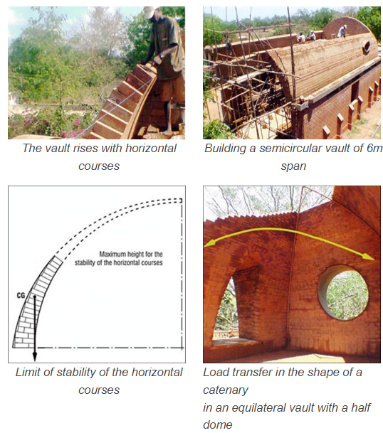
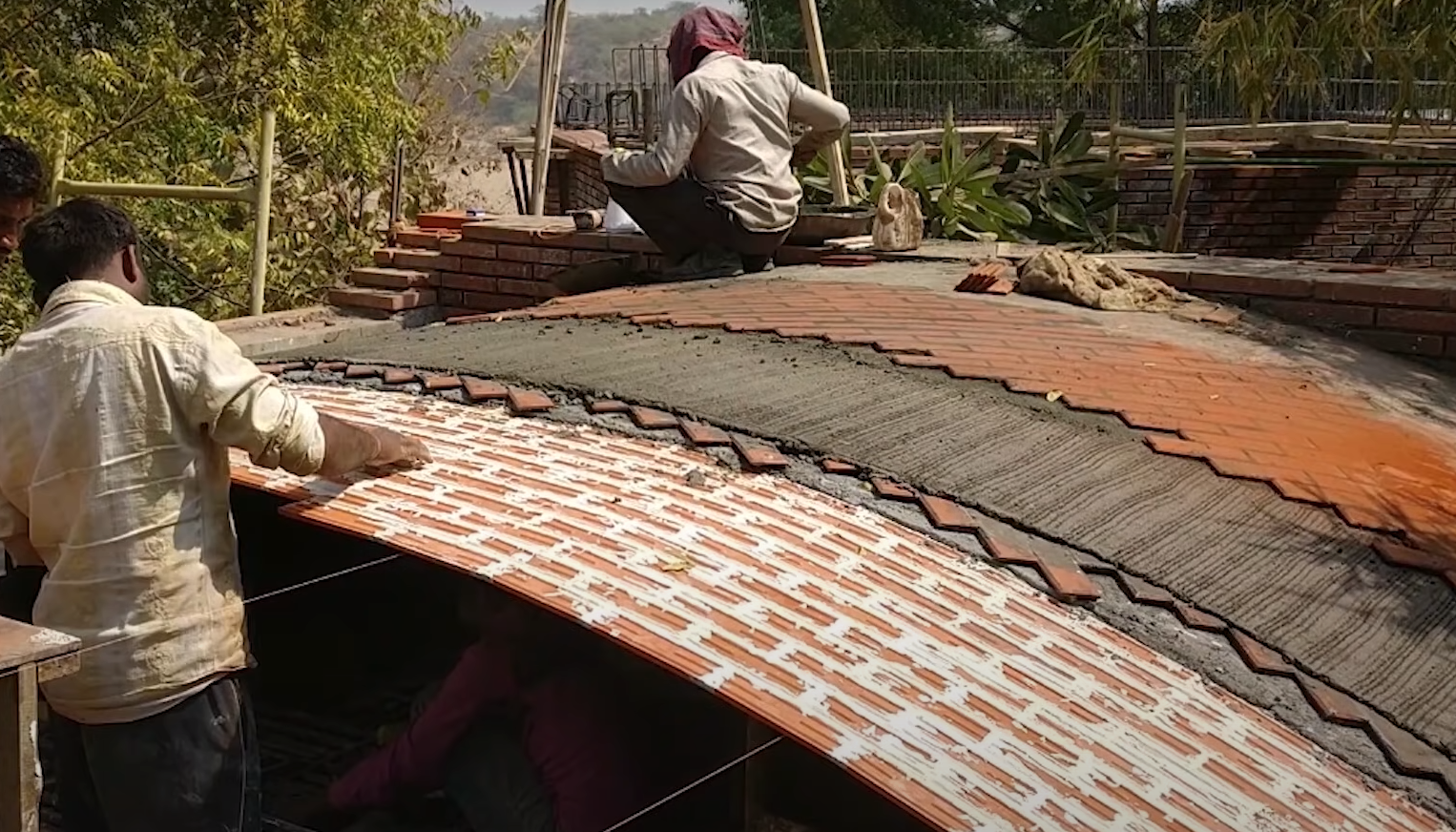
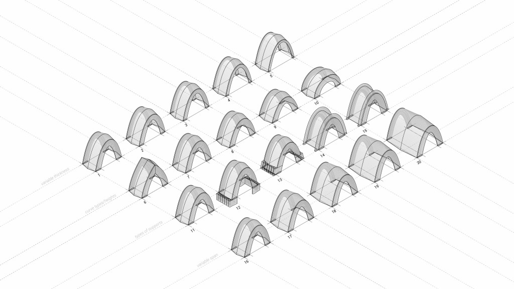
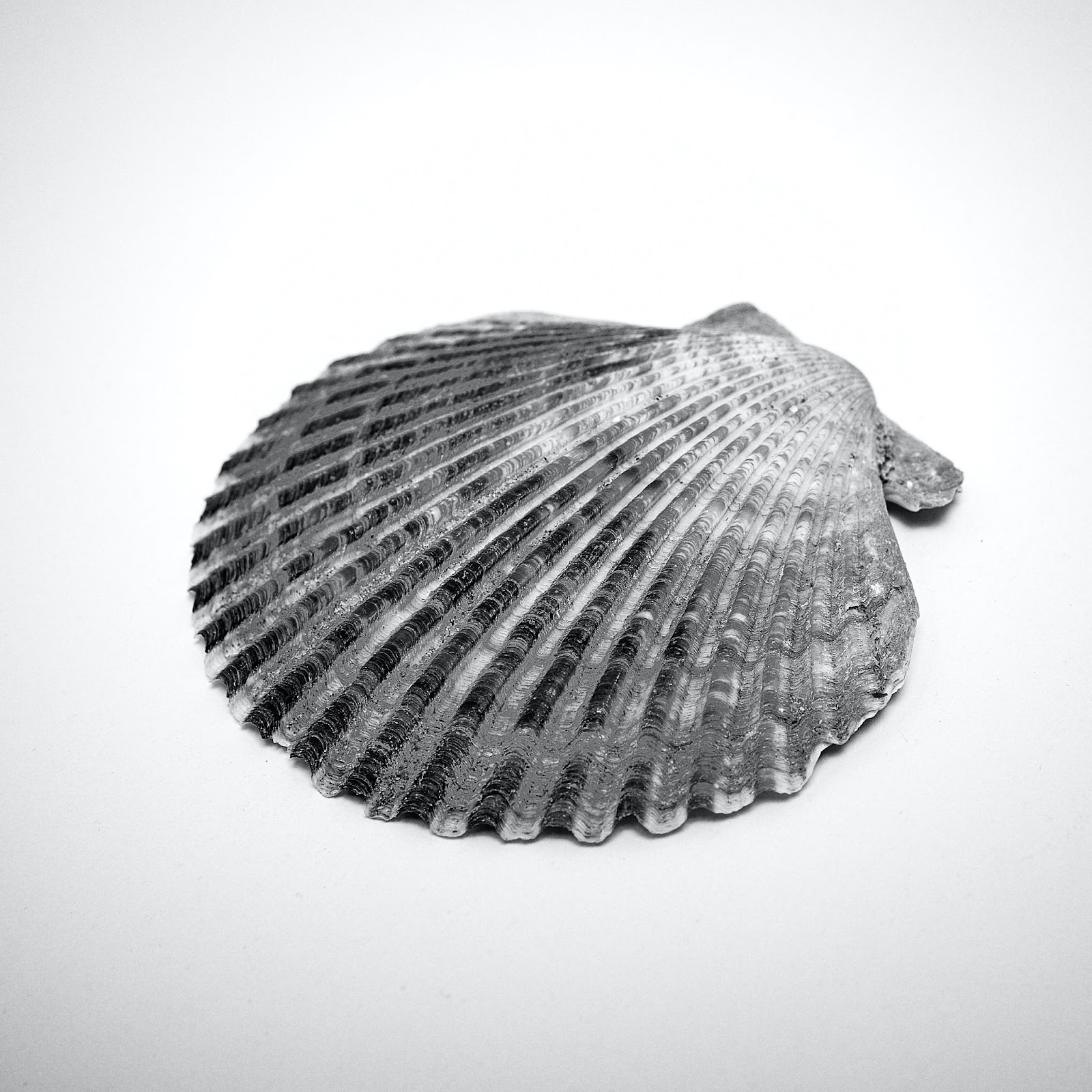
In an effort to understand the different types of vaulted structure and the secrets behind their structural performance, it was prudent to investigate and interrogate the structural characteristics of some vernacular and conventional vaulted systems. We took interest in a number of vernacular techniques used in the construction of self supporting vaults such as the Nubian vault and the timbrel/catalan vault. We also referenced related previous 3DPA research works to understand their developments in achieving printable vaulted structures. Additionally, We also drew inspiration from structural solutions found in nature that relate to innate rigidity and stiffness where required in organic forms; particularly from the ribbed surface of the bi-valve scallop shell.
“Free-spanning technique” is a development of Hassan Fathi’s Nubian technique, by Auroville earth institute.
Construction process of building a timbrel vault, by Kakani Associates
A catalogue of geometries developed in previous 3DPA research
One half of a bi-valved scallop shell. Photo by Ricardo Diaz and Unsplash
Prototyping Setup
With the knowledge gathered from the above case studies, it was time to set an experimental set up for our study and establish study parameters for printing. For rapid prototyping, a desktop 3D printer modified for 3D printing was at our disposal, with the capability of making 1:10 scaled models. The designed prototypes were also confined to a bounding box of 200 x 200 x 200mm.
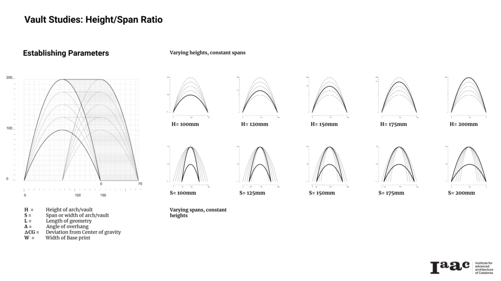
Establishing Parameters for Printing Vaulted Geometries
Taking insights from earlier 3DPA work, we proceed to establish some working parameters of study that we could use to swiftly test on simple barrel vaults. The parameters below were selected.
- H = Height of arch/vault
- S = Span or width of arch/vault
- L = Length of geometry
- A = Angle of overhang
- ?CG = Deviation from Center of gravity
- W = Width of Base print
………………………………………………………………………………………………………………………………………………………………………………………………………………………………………………………………………
Experiment Setup 01
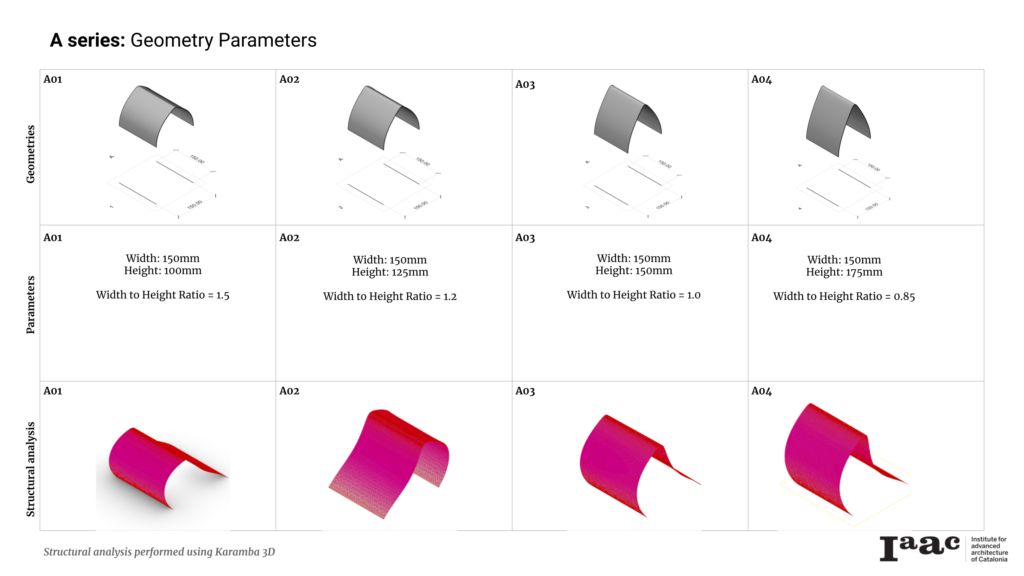
Catalogue A
For this set up, the span (S) of the barrel vault was kept at a constant of 150mm. The range of variance of the heights (H) were set between 100mm and 200mm, with 50mm increments. The base width (W) equaled the thickness of the nozzle to be used during the prototyping. The aim here was to test the parameters as well as to make observations of successes and failures of the 3D printing processes in printing simple vaults.
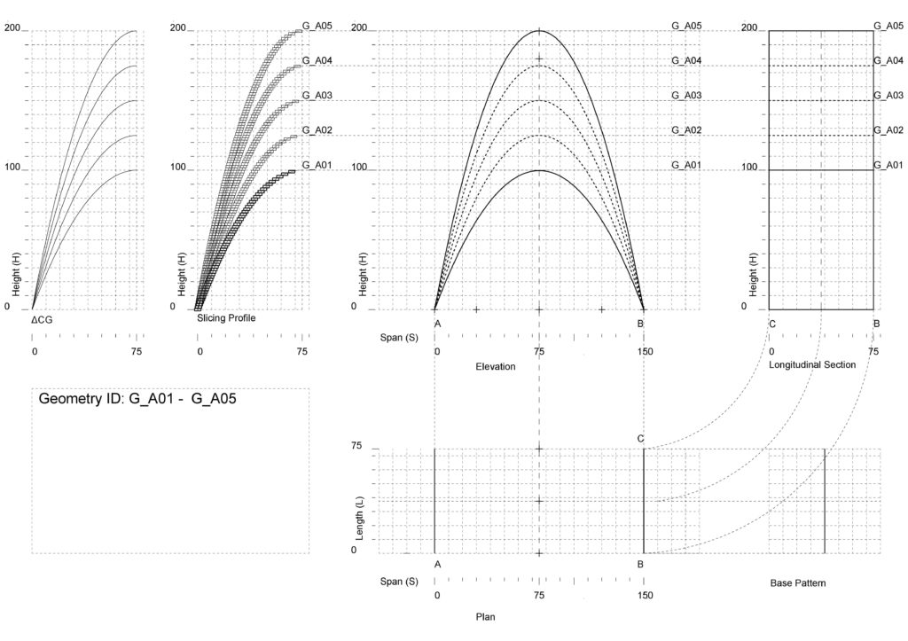
A catalogue of 5 simple geometries was created using Rhino + Grasshopper and structural analysis was performed using Karamba 3D. The structural analysis conducted suggested that all five geometries would experience structural failure.
Using a nozzle size of 3mm and a slicing distance of 1.5mm, prints were made in order of sample A01 to A04 – lowest to highest in height, keeping the span fixed. The results are as seen above. Sample A01 collapsed at layer 30 while A02 and A03 collapsed at layer 34 each. Sample A04 collapsed at layer 24. Based on these results and those from the structural analysis, A05 was assumed to be compromised and was therefore not printed. The table below shows the print results.
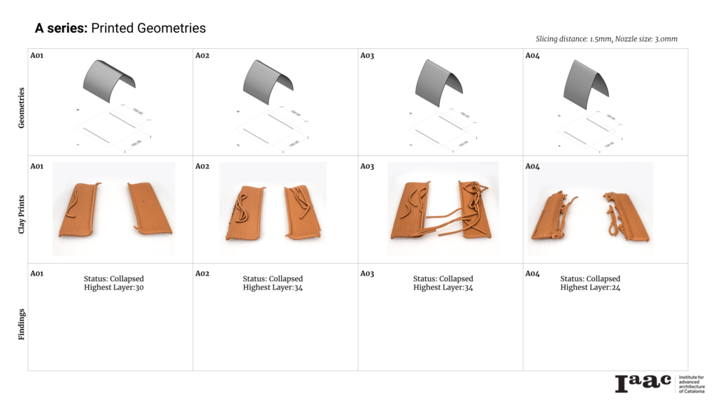
Catalogue A: Findings
All four geometries failed and collapsed. The collapses occurred due to the reasons below:
- Very narrow Base Width; this resulted in a small base area/footprint for any of the prints to take on the distribution of mass without buckling under self weight. Also, in this state, the geometry is considered to have low global inertia, which only gets worse with every additional layer of print.
- Deviation from Center of gravity; As the base is too narrow, it takes very little to push the Center of gravity away from the base. The prints would therefore not follow the arch line of the barrel vault successfully and would fail around layer 25 – 30.
With the above lessons in mind, a new catalogue was created to attempt to address the failures of the first experiment.
………………………………………………………………………………………………………………………………………………………………………………………………………………………………………………………………………
Experiment Setup 02
Catalogue B
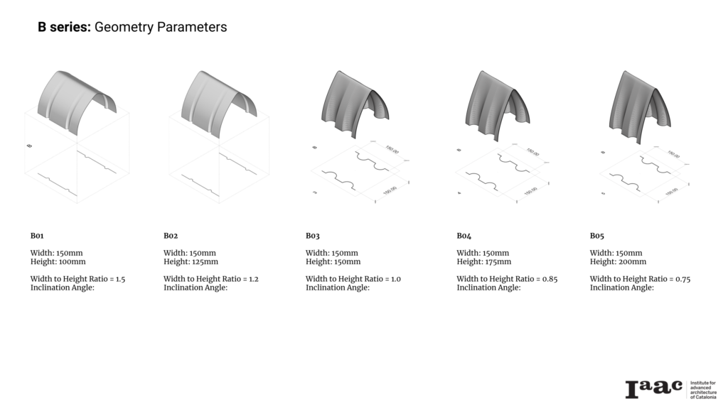
For this set up, a catalogue of 5 geometries was created with adaptations made to increase the base width and increase global inertia. A semi-circle was introduce onto the base pattern used to create the geometry. This reduced the effective span at the middle of the vault and increased the overall base width of the base pattern. Refer to the drawing setup below. The range of variance of the heights (H) were maintained as before ;between 100mm and 200mm, with 50mm increments.
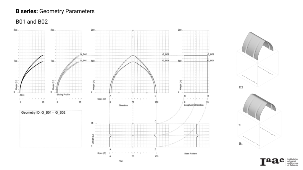

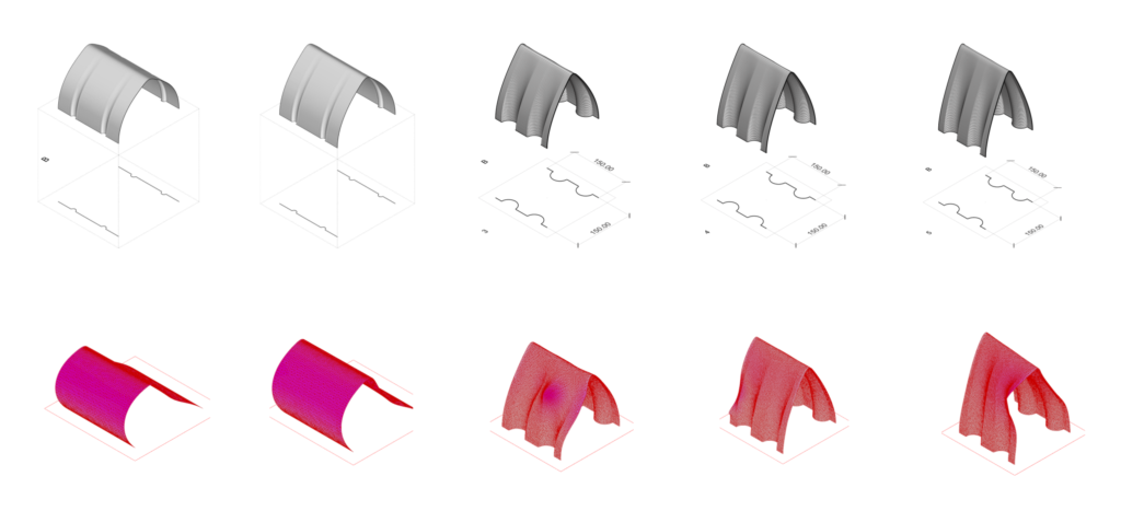
The geometries underwent similar structural tests as before. As seen above, the results suggested that all five geometries would experience buckling , but have better structural performance than in those from catalogue A.
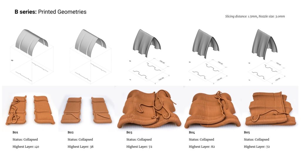
Using a nozzle size of 3mm and a slicing distance of 1.5mm, prints were made in order of sample B01 to B05 – lowest to highest in height, keeping the span fixed. The results are as seen above. Sample B01 collapsed at layer 40/67 while B02 collapsed at layer 34/84. The results of these two were slight improvements from the first catalogue. Therefore, it was decided to increase the base width further for the remaining tests on catalogue B. (B03 – B05)
B03 collapsed at layer 72/100, B04 at layer 80/117 and B05 at layer 72/134. See the outcomes below.
/
Catalogue B: Findings
All five printed geometries failed and collapsed, but also gave better structural results, compared to those in catalogue A. Below are the observations of failures and improvements.
- Base Width; The introduction of the semi-circles at the base altered the geometries, making them slightly more resistant to buckling when compared to the results obtained from the first catalogue. This alteration increased the global inertia and made it possible for the prints to take on a little bit more distribution of mass without buckling under self weight.
- Deviation from Center of gravity; This alterations increased the geometries base width, thereby decreasing the deviation from center of gravity. Increasing the base width further would therefore yield more stable prints.
During printing, it became apparent that geometrical weak points could be corrected/strengthened by decreasing instances of low global inertia. This meant moving away from straight line geometries.
……………………………………………………………………………………………………………………………………………………………………………………………………………………………………………………………………..
Experiment Setup 03
Catalogue C
Another catalogue of 5 geometries was created with adaptations made to incorporate the lessons learnt. This time, the base pattern was made from a curvilinear curve as shown in the drawing setup below. It was anticipated that this geometry alteration would create a firm base for the geometries. Due to the longer curve, more material would be deposited at the bottom of the print.
In an attempt to optimize material usage, the curve at the base of the arch line was set to loft up to a single straight line at the top as shown in the setup below. The range of variance of the heights (H) were maintained as before ;between 100mm and 200mm, with 50mm increments.

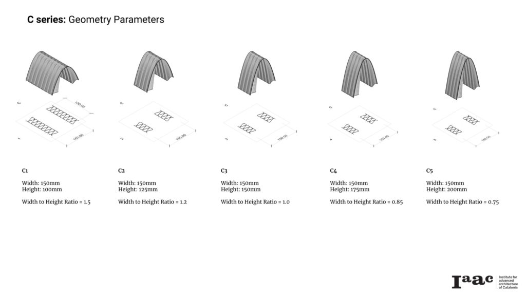
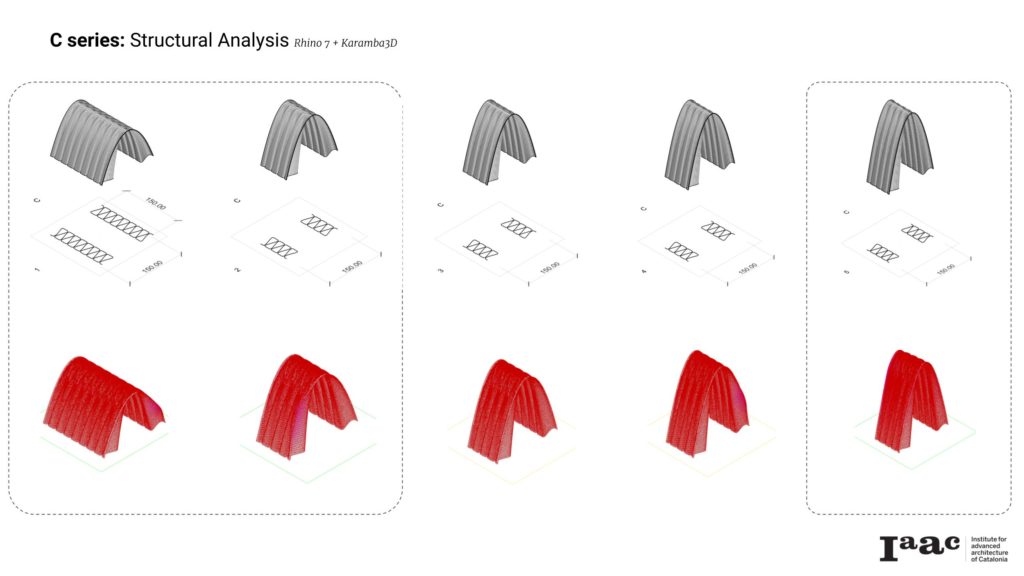
With the new setup in place, a new catalogue was created and similar structural tests were performed in Karamba 3D. All five geometries appeared to be structurally sound. Two models on the extremes of our catalogue spectrum were selected for printing. It was assumed that if both printed successfully, all the geometries in this catalogue would yield successful results.
With the successful printing of C01 and C05, C02 was selected and printed as the final test of the catalogue.
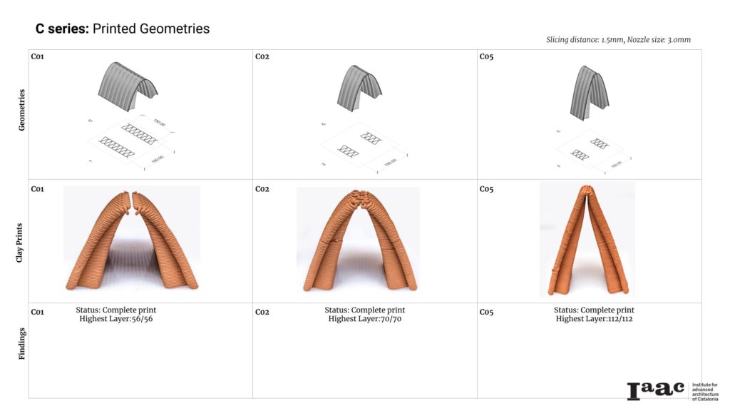
Catalogue C: Findings
All three selected geometries printed were able to print to completion. This was a significant improvement from the results of the previous experiment. The increased base width and mass distribution strategy made the geometries more stable. The new base pattern adopted also increased the rigidity of the geometries.
However, new observations were made.
- Arch connections at top; Even though the geometries resulted in stable prints, it was noted that the geometries would barely touch at the apex of the arch line instead of joining neatly as seen in their digital twins. This was a geometrical issue caused largely by the attempt to reduce mass at the top of the each geometry, by lofting up to a single line.
- Arch line deformation; It was also noted that the arch line of the tallest print (CO5) was deformed, even though the printing was successful.
The geometrical issues above would need to be corrected in order to successfully close up the geometry and create a structurally sound 5th facade.
……………………………………………………………………………………………………………………………………………………………………………………………………………………………………………………………………..
Geometry Optimization
With the results and observations obtained from the initial prototyping phases, the next step was to select a single geometry for further exploration and prototyping, with the aim of optimizing the structural performance through geometry design.
The following were the objectives considered as guide for the next experimental phases.
- To optimize the design of the base curve for better support.
- To improve the geometry to reduce wet state deformation during printing.
- To improve the geometry to allow a seamless joint at the apex of the vaults
- To further develop strategies to create larger, more complex geometries through merging of connection of simple vaults.
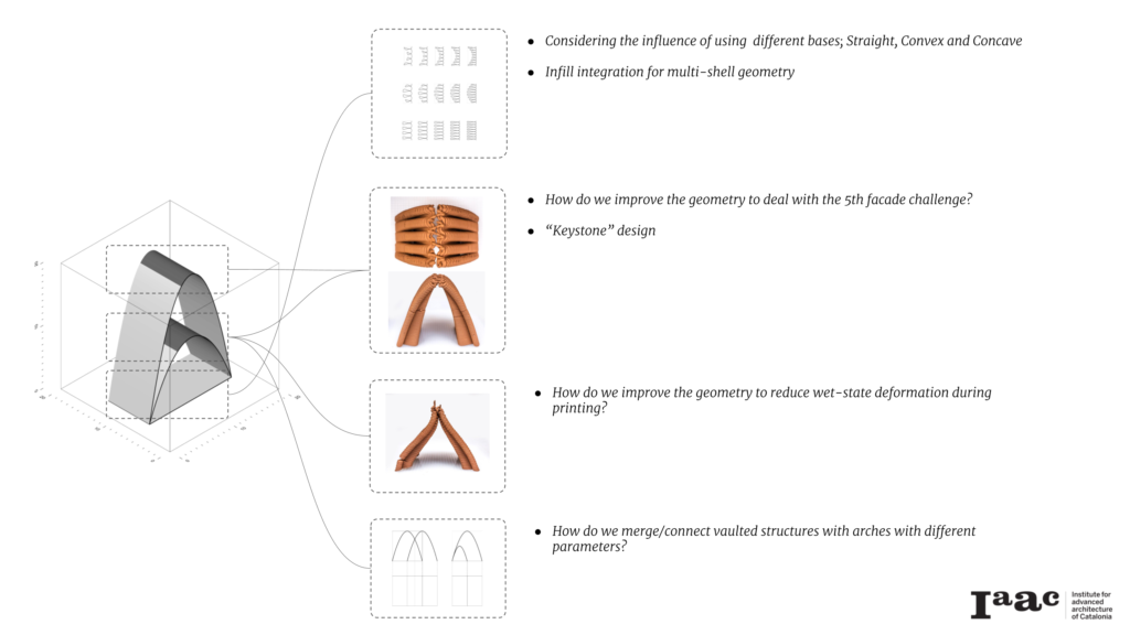
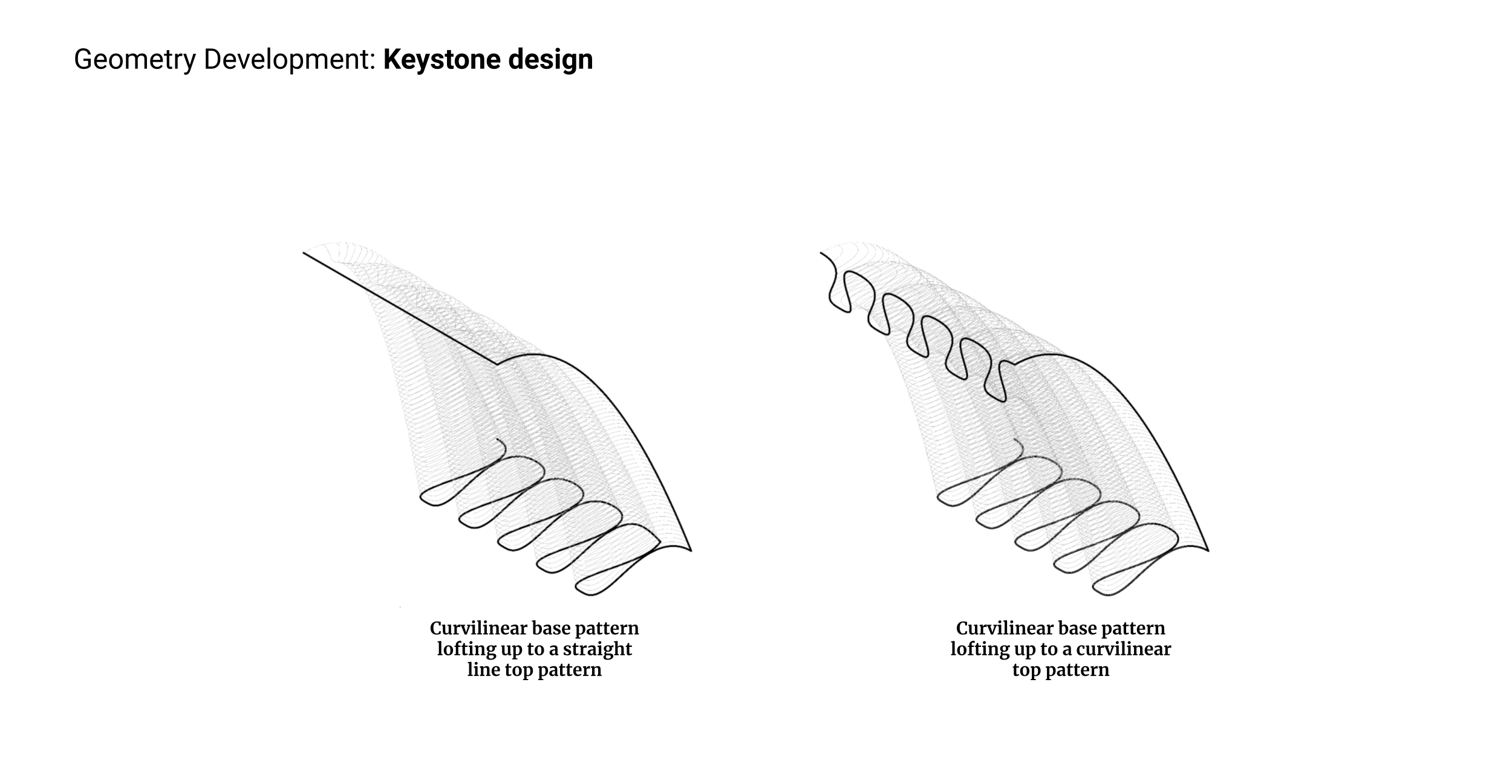
‘Keystone’ Study
Improving the geometry to allow a seamless joint at the apex of the vaults
Using the parameters used in the generation of geometry CO1 (span/width to height ratio of 1.5 ), an adjustment was made to increase the thickness of the apex. This was done by lofting the curvilinear base pattern to a perpendicular curvilinear top pattern, as shown in the illustration below.
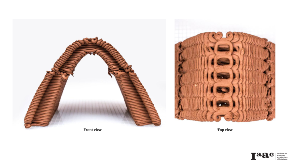
The geometry was then printed to completion using a 3mm nozzle and slicing distance of 1.5mm. During printing, a sudden loss of pressure was experienced and resulted in the defect visible on the from view, but the print was able to continue to completion as seen above. The following observations were noted.
- The apex was able to form, leading to a complete vaulted geometry. However, as seen in the top view above, the slicing of the geometry did not allow for the full closure of the roof. the expectation was to completely close the top of the geometry. Therefore, further geometrical design interventions would be required to make it possible to completely close the roof.
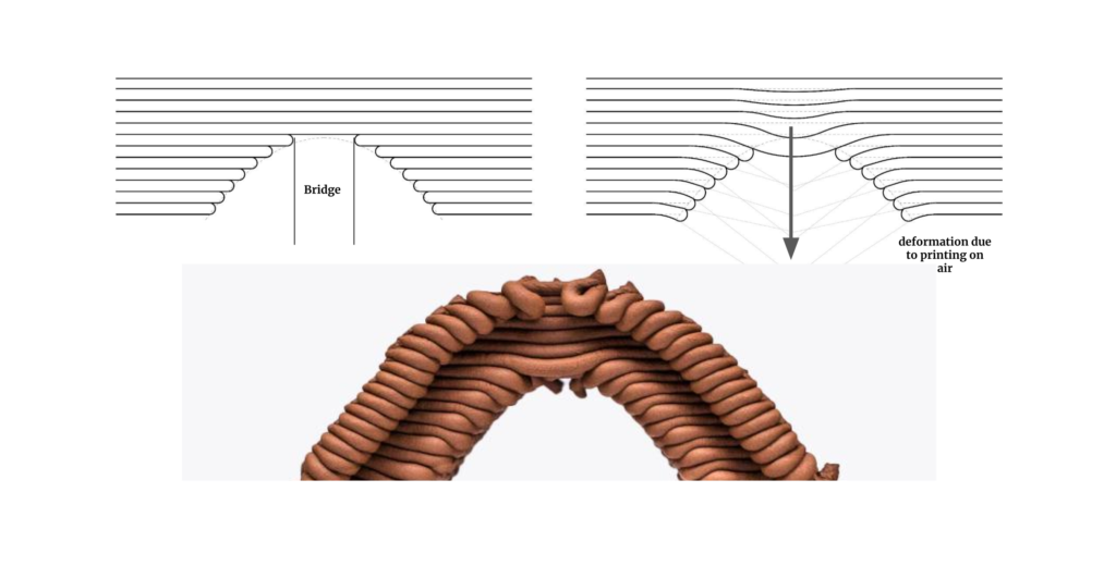
- As a result of the parameters used in generating the model, a ‘bad bridge’ was inadvertently created, leading to minor layer-sagging as seen in the image below.
Base Support Study
Considering the effects of using straight, convex, concave and adaptive base shapes
The base support of the geometries were also put in question with the aim of optimizing material consumption during the printing process. This part of the exploration sort to find out the effects of altering the shape of the base to see if it was possible to achieve a relatively rigid vault. Beyond the normal straight base, convex and concave options were considered.
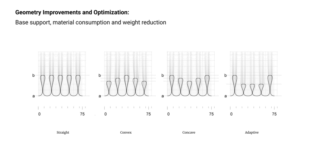
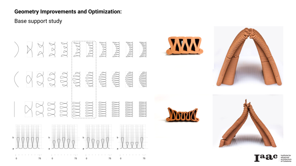
Preliminary conclusion were made to rule out the testing of the convex base option as those would drastically reduce the internal span of the geometries. Using the same parameters as geometry C02 and only replacing the base pattern with a concave option, a prototype was generated and tested. As seen in the image above, the print was not able to keep the original form due to buckling. The concave base pattern as used in this instance failed to offer adequate support to the mid-sections the geometry.
Responding to the above, an adaptive/performative strategy was developed by moving on from single shell geometries to multi-shell geometry design process, by introducing infills. The introduction of infills would give the geometry the flexibility to adapt to structural demands in specific areas of the geometry.
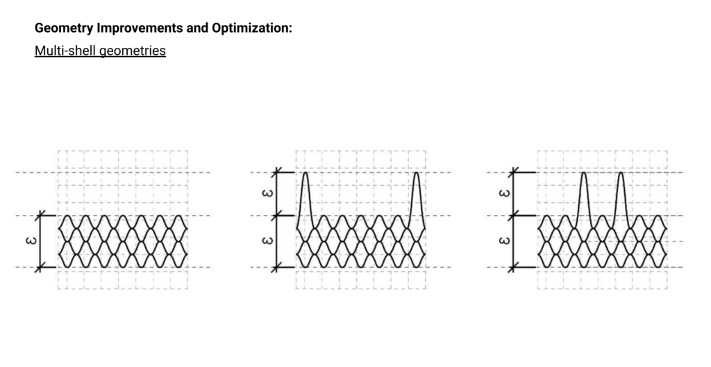
The multi-shell geometry also allows for a seamless closure of the roof. As seen below, shell 01 needs to be printed successfully, as it will become the ‘scaffold’ for shell 02. Shell 01 and 02 will then support the printing of shell 03 and 04, allowing for the neat closure of the 5th facade. This construction sequence is similar to that of the construction of timbrel/ catalan vaults.
Construction/printing sequence of the 4-shell geometry
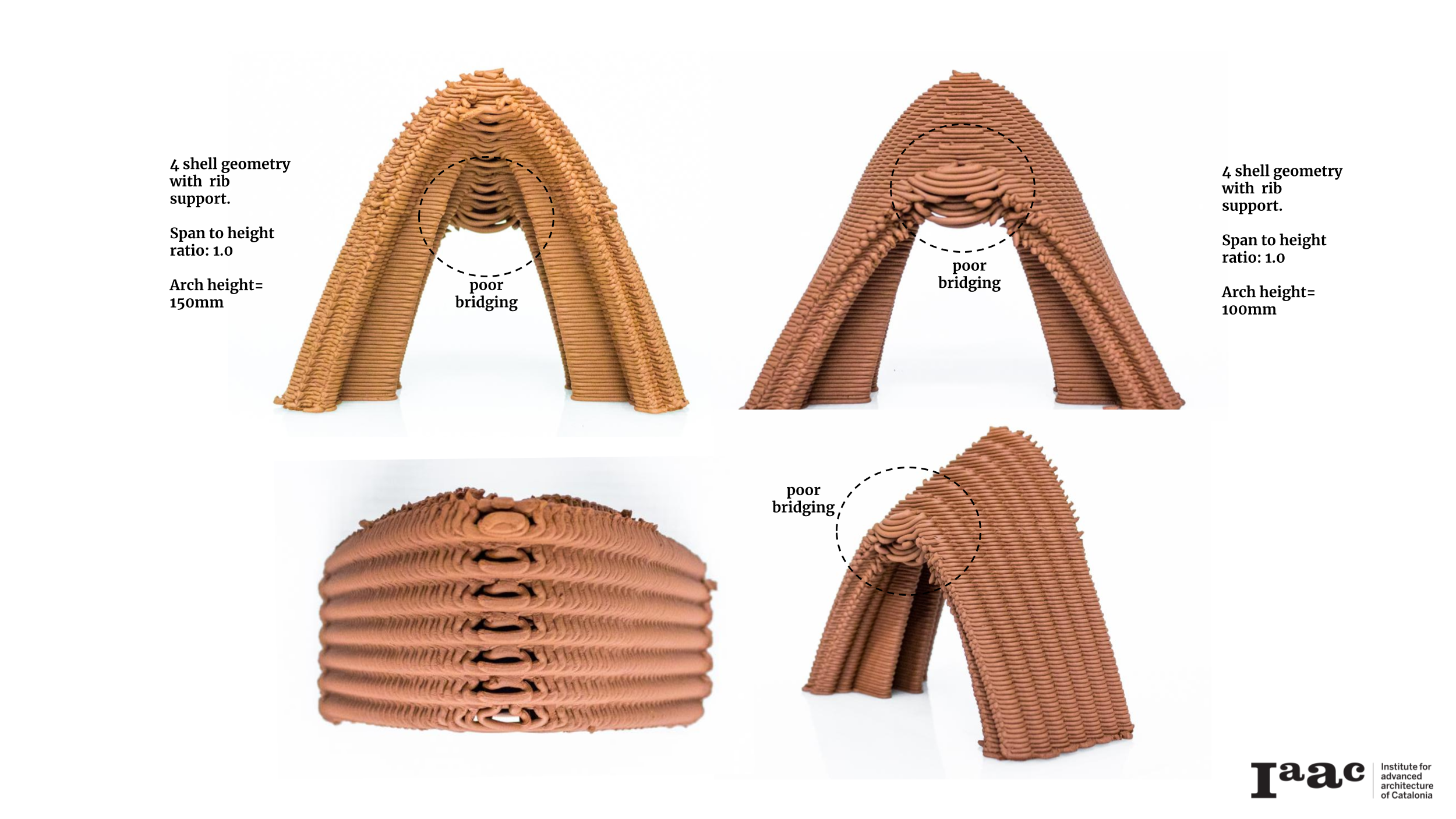
Using the multi-shell approach, several geometries were developed based on the parameters of geometries C01 and CO3 (span to height ratio of 1.0 and 1.5 respectively). See catalogue below
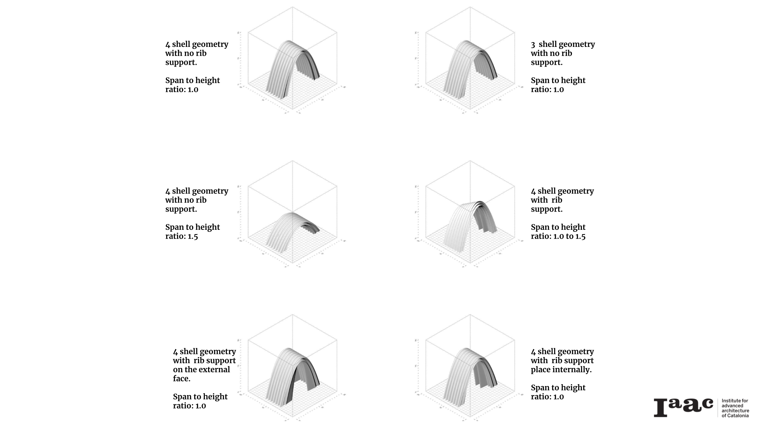
The first to be prototyped was the 4-shell geometry (span to height ratio of 1.0) without support ribs. The printing process run smoothly but the geometry collapsed as a block during printing. This was attributed to the increased mass of the geometry. Two solutions were quickly tested in response. A 3-shell geometry of the same parameters was developed and printed. This too failed in a similar fashion.
It was then decided to test out a 4 shell geometry with a lower height (Span to height ratio of 1.5), without adding support ribs. This also collapsed in a similar way, towards the final stages of printing as seen below.
In the above prototype one half of the geometry collapsed while the other remained stable. It was therefore decided to reprint the same geometry again to investigate whether better success would be achieved without support and compare it with a similar geometry with supports.
Both geometries printed successful but without deformation as seen below.
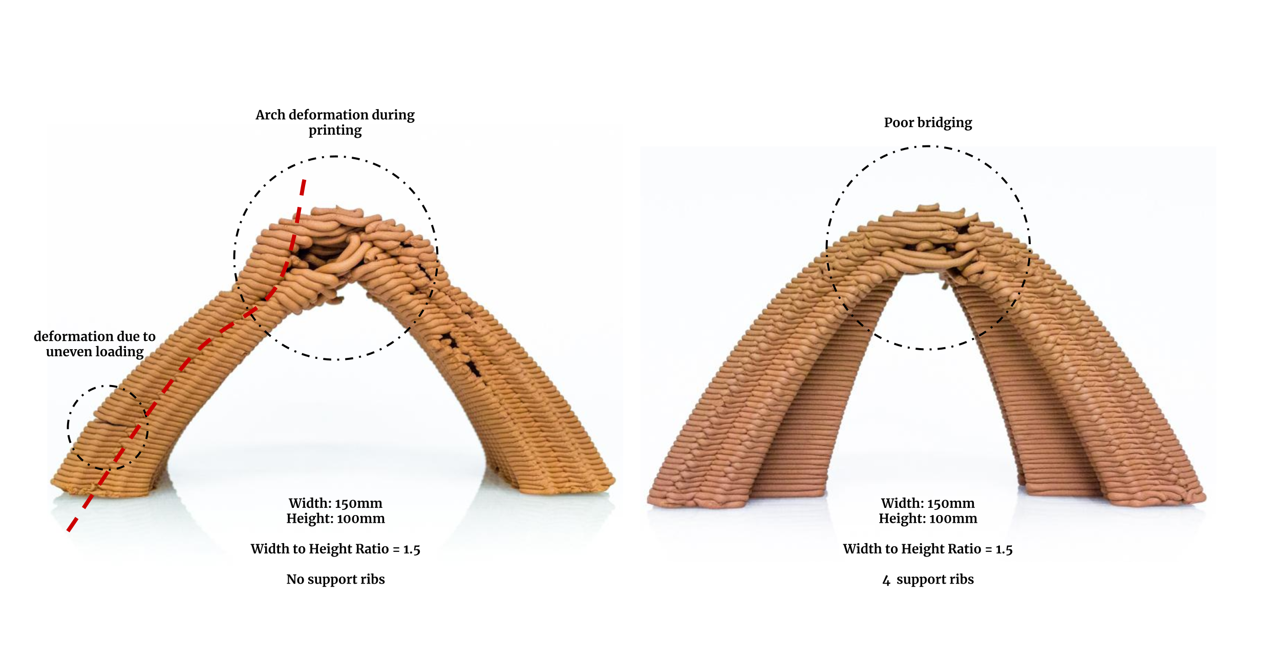
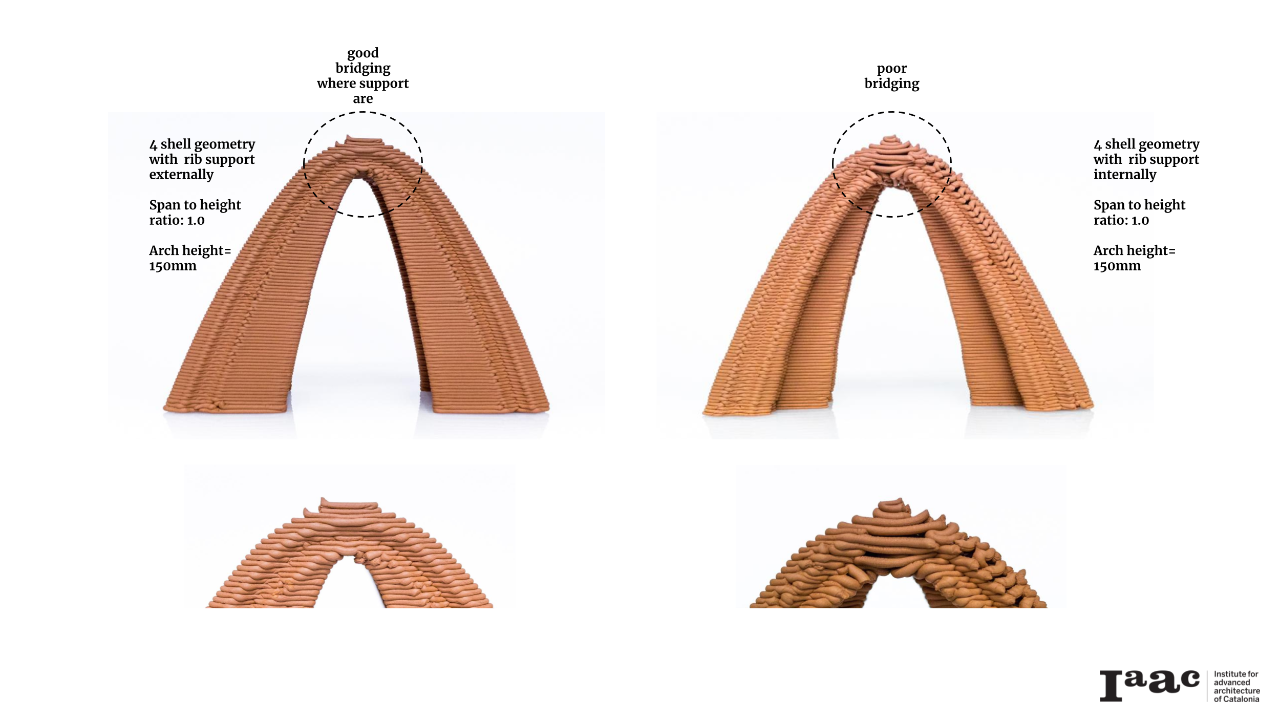
The next prototypes were based on the geometries developed using the width to height ratio of 1.0, (hence width = 150mm and height = 150mm) with the introduction of support ribs internally on one prototype and externally on the other.
The next prototype featured two arches from both set of parameters on the front and back, resulting in a sloping vault.
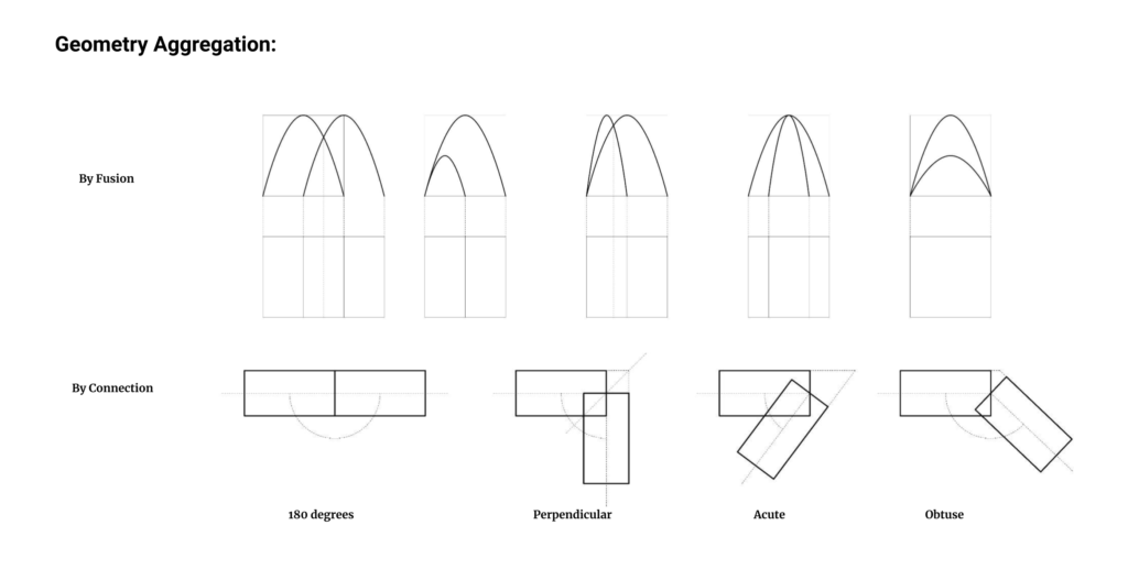
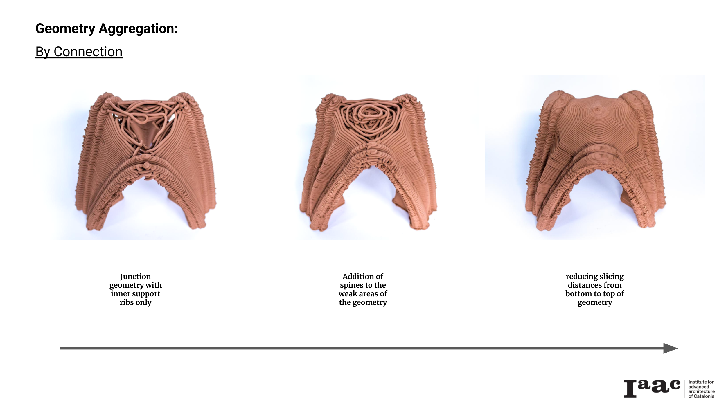
Geometry Aggregation
The next prototyping phase sort to explore ways to develop self support for complex vaulted geometries. Two strategies for developing geometries were chosen.
- Fusion: the merging of vaulted geometries of same or different parametric configurations, by pushing their sides against each other, to create a single unified geometry.
- Connection: the bringing together of two or more vaulted geometries of same or different parametric configurations, by aligning their arches and filling the negative space to make a single form.
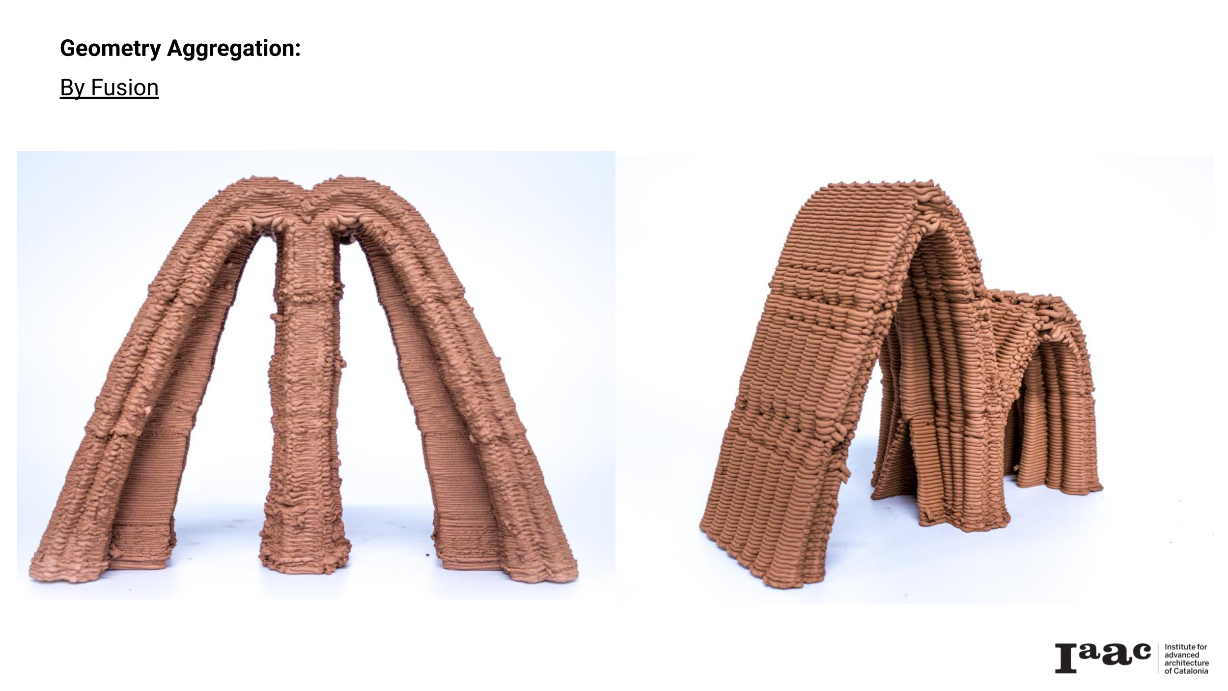
Fusion
Two geometries below were developed using the parameters from the previous exercise. One attempted to fuse two geometries with the same span to height ratio, while the other attempted to fuse vaults with different ratios.
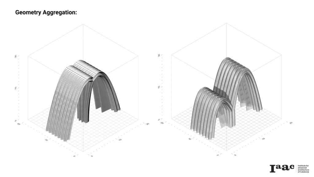
The first approach resulted in a geometry that required a central core to support the large span created as a result of the merger. Otherwise, it wouldn’t be possible to print the span successfully. The second attempt to link the resulting span by introducing an vaulted opening on the central wall.
Connection
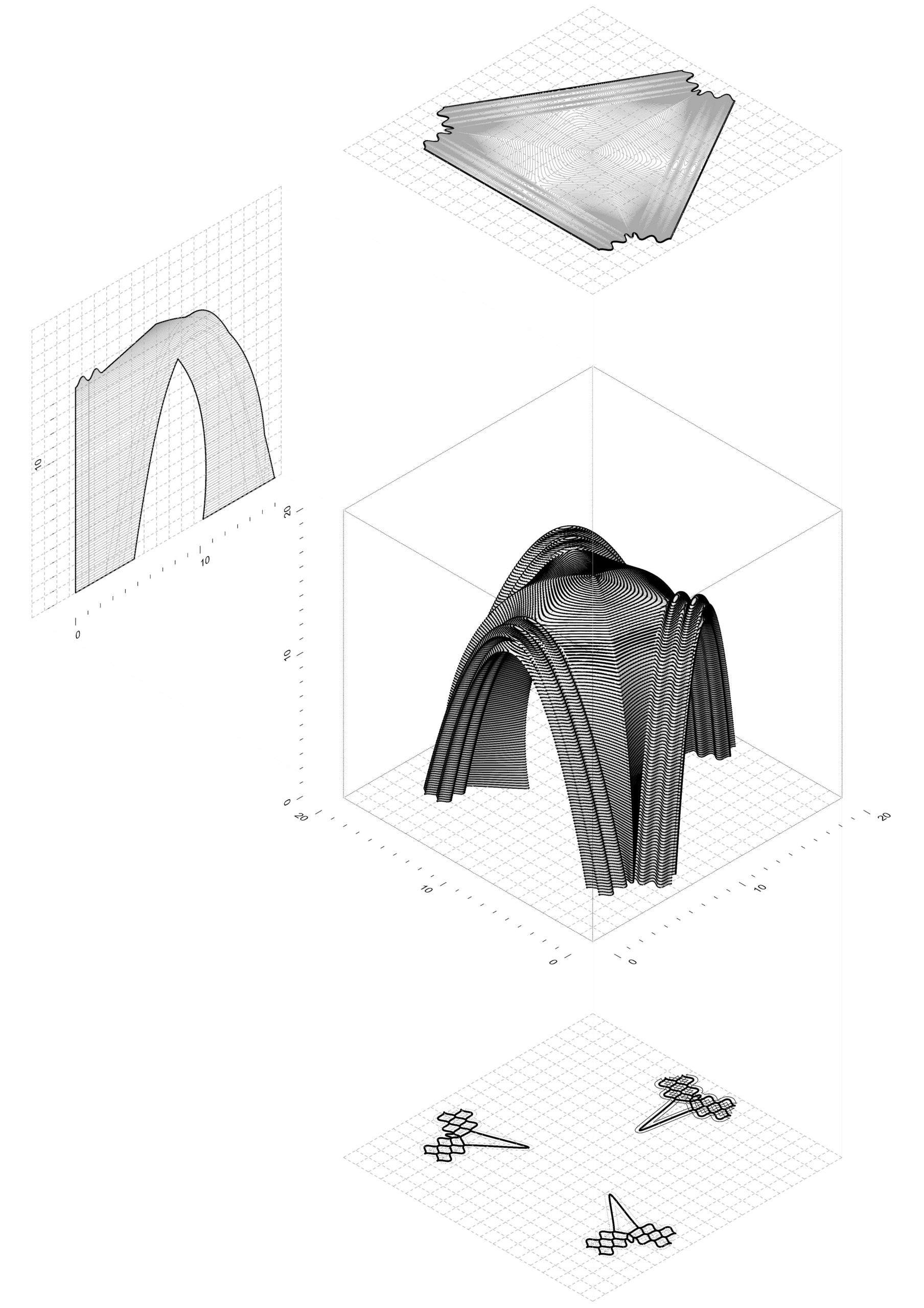
The connection exercise attempted to create a junction geometry to connect 3 vaulted geometries of similar parameters. The span to height ratio of 1.0 was selected as it had given the best outcomes in previous explorations. Based on those parameters, several iterations were developed and printed to achieve the final successful geometry seen below.
Challenge 01: Self-support
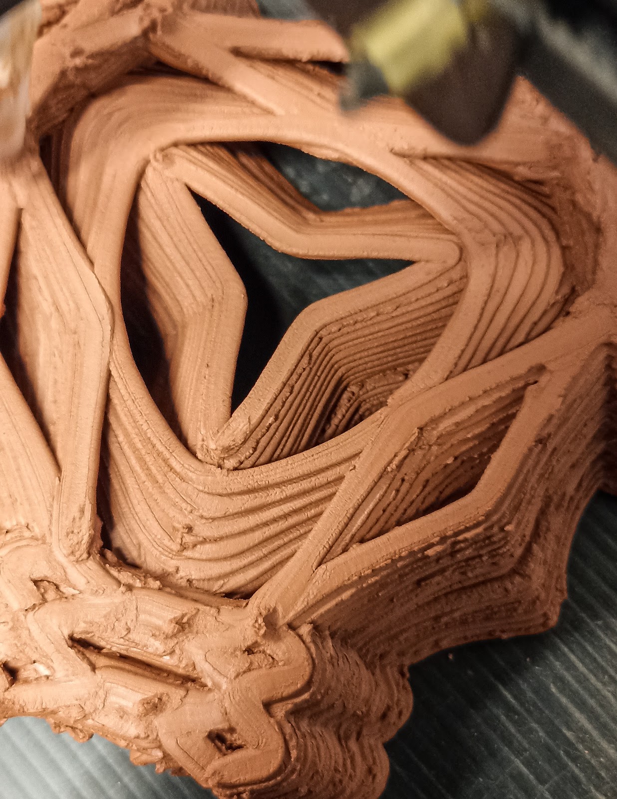
The main challenge in the development of this prototype was the closure of the 5th facade. Because of the low roof angle the printing process would be trying to create and connect three cantilevering structures to form one form. A multi-shell approach (explained earlier) was employed and designed to provide the needed self-support for the legs and the roof enclosure during printing process. The strategy works as shown below.
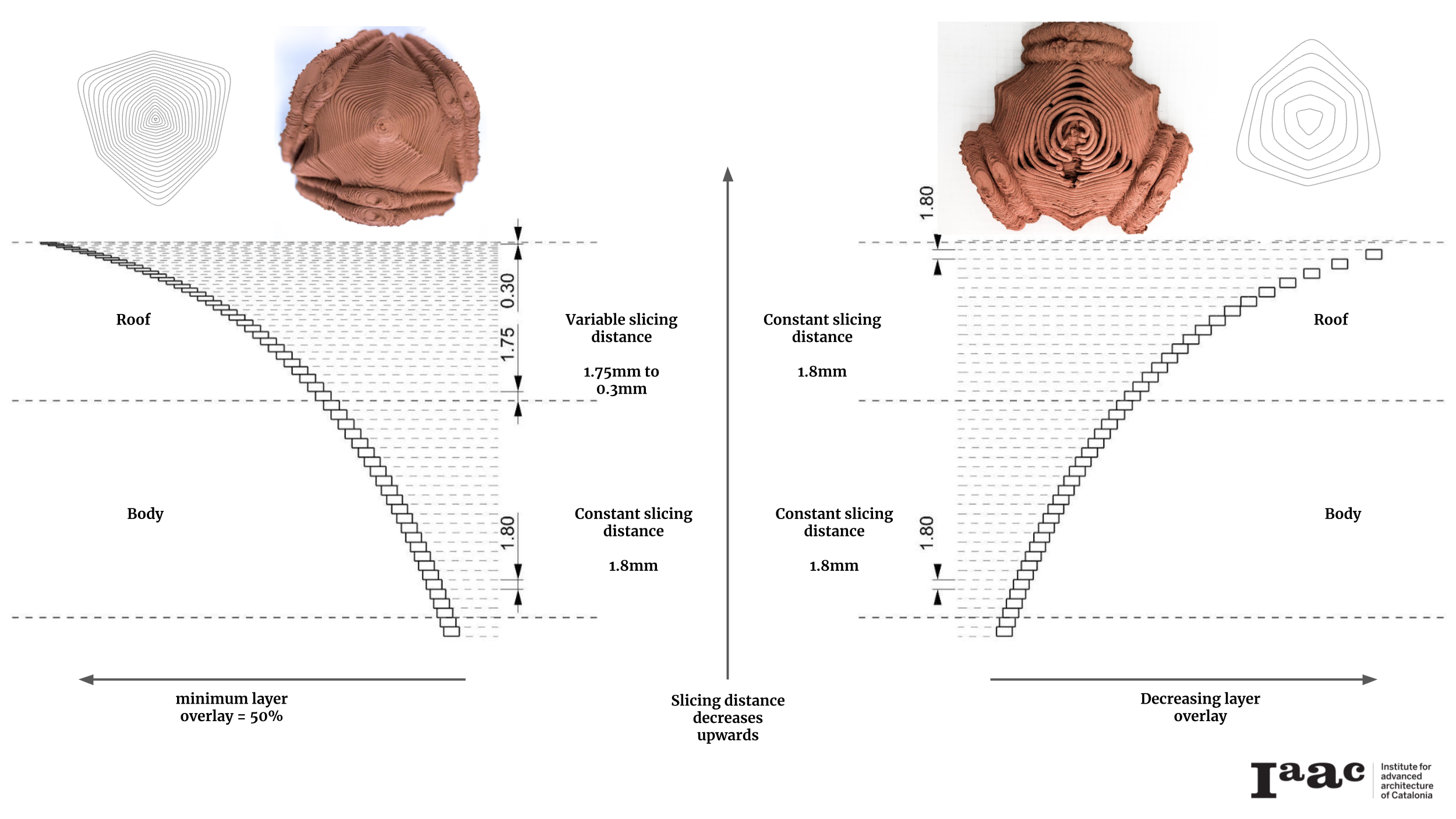
Challenge 02: Layer overlaps and Slicing distance
The multi-shell approach was able to provide the necessary support required for printing. However the neat closure of the roof remained a challenge. This was due to the reduction of surface area in contact between the printed layers at the roof. This happens because the of the sudden angle change (from steep to shallow) at the top of the geometry. Reducing the slicing distances for the entire model would correct this by increasing the number of layers, and thereby increasing the surface area in contact between overlapping layers.
However, while applying a smaller slicing distances leads to cleaner printing of geometries, it also means more printing time and more material consumption. Therefore, an optimized approach would be to slice the legs and the roof using different slicing distances. In this example, a grasshopper definition was used to create variable slicing distances, decreasing from bottom to top. This resulted in a final homogenous print with a neat roof.
Further Exploration
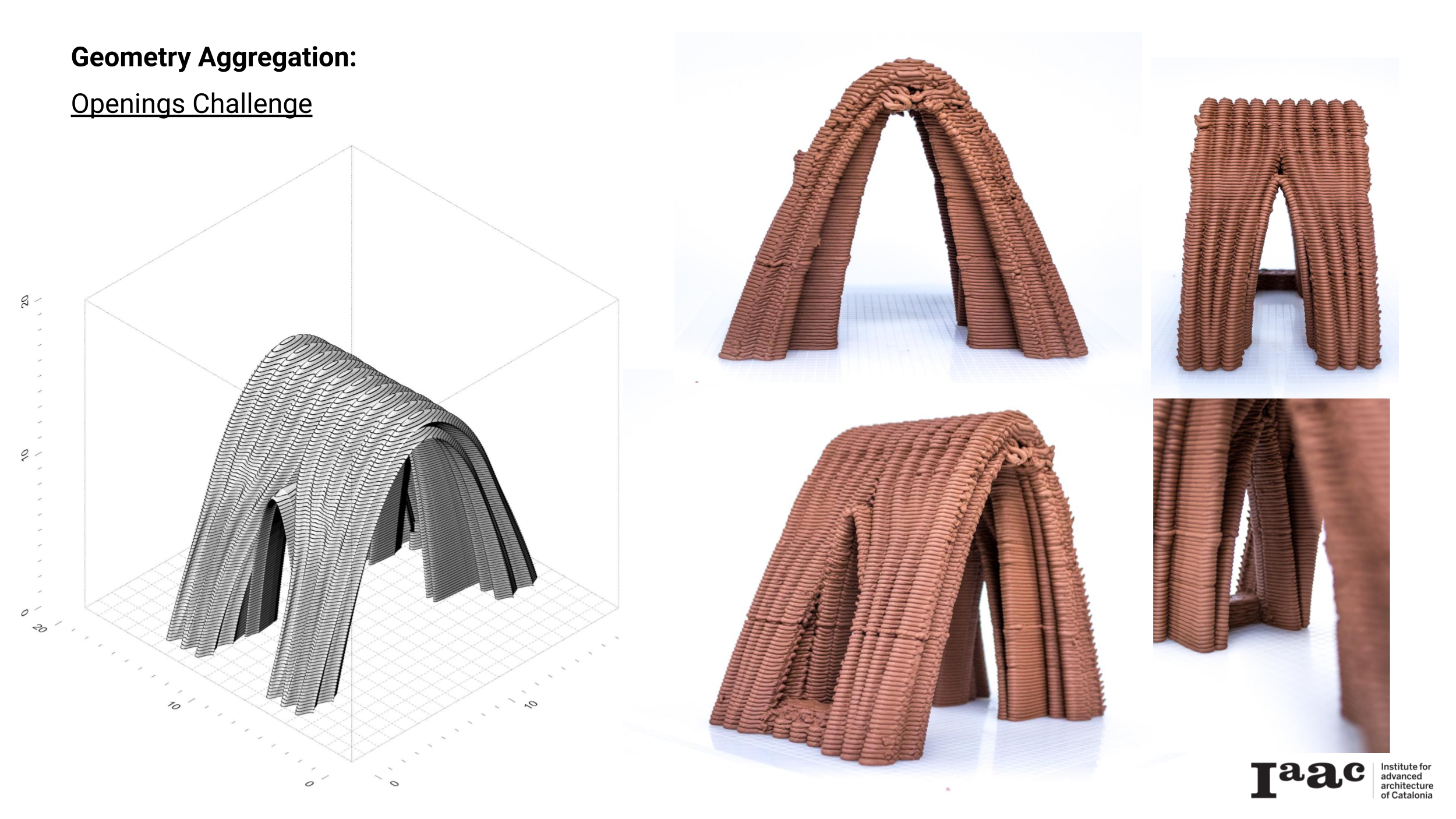
Openings Challenge
The challenge of creating openings on the walls of the vaulted while maintaining its self structural support. For this exercise, modifications were done to the vaulted geometry with an equal span to heigh ratio developed earlier, to create a version that incorporates a ‘window within one wall and a ‘doorway’ on the other.
The creation of the opening took inspiration from the Tecla project designed by Mario Cucinella Architects and build by Wasp.
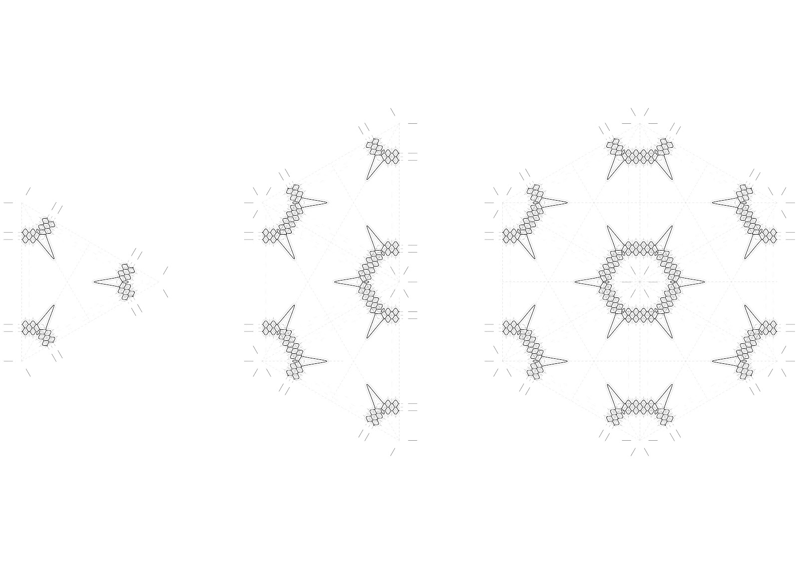
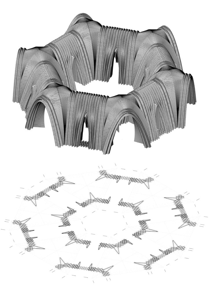
Modularity
With the prototypes prepared and printed, a modular setup was imagined, using the junction vaults to bring together simple vaults to create a network.
……………………………………………………………………………………………………………………………………………………………………………………………………………………………………………………………………..
Conclusion
The use of multiple infills in the development of geometry for 3D printing – as demonstrated in the above set of experiments – allows for performative adaptation abilities for the geometry. In this research, the infills were fundamental for the development of structural support where needed, to give the different kind of geometries rigidity/stiffness and stability. This adaptation ability can be controlled parametrically to intelligently offer the required structural functions using the optimum amount of material.
Specifically for the closure of the 5th facade by 3D printing, minding the layer overlaps is crucial to ensure both the structural integrity of cantilevered prints and complete enclosure. Combining an optimum layer to layer overlap width with the intelligent use of multiple infills allows for the successful printing of shallow angled sections of geometries, allowing this parts to support their own weight while defying gravity.
……………………………………………………………………………………………………………………………………………………………………………………………………………………………………………………………………..
