

The state of the art shows our pursue to develop organic geometries using

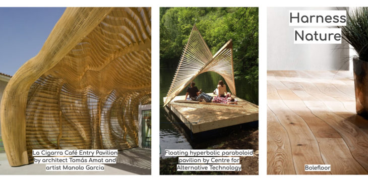
Hyperboloid as design geometry
- Achieve a variety of double curves by using straight lines
- Geometry is the structure
- Easy to reinforce by adding additional structural lines
- maximum utilization of offcuts
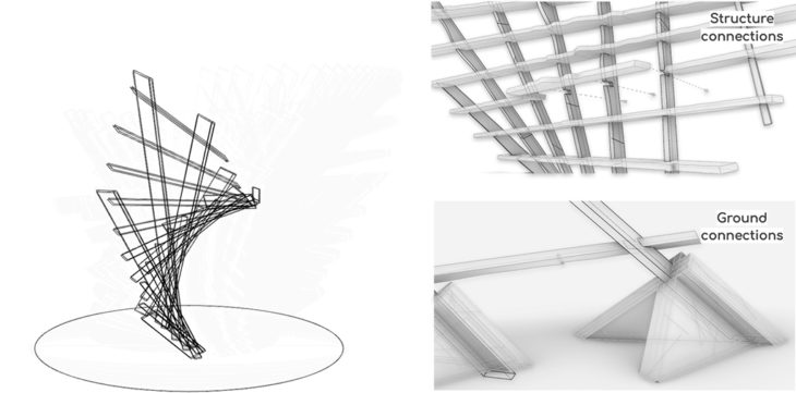
The design takes advantage of the offcuts grain to create a rigid waffle-like structure. Horizontal and vertical members and then connected through notches and screws to stiffen the system. The outer horizontal members of this grid present bark since they are directly taken from the offcuts sides; connections are carved in these portions. On the other hand, the inside vertical elements are extracted from the offcuts inner parts.
For a smaller prototype, approximately 54 pieces are expected. The estimated fabrication time of 56 pieces is 8 hours, and the assembly with a wooden base is expected to take approximately 1 day.
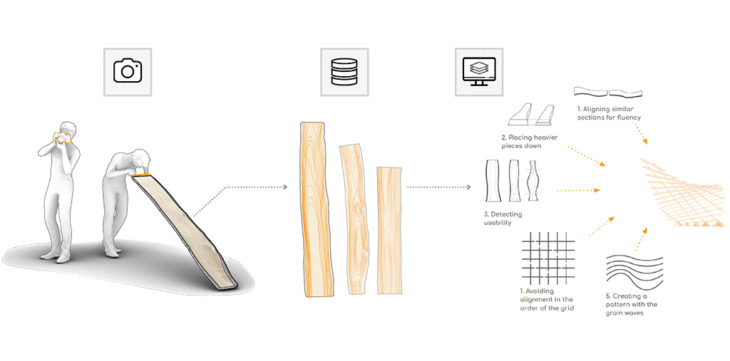
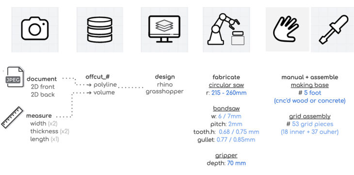
Scan: this part consists of 2D documentation of the pieces with their measurements.
Database: images are post-processed to get the polyline of the grains, and this data is uploaded into the database with the corresponding piece’s id number and dimensions.
Design: The collected data could be processed for the purposes of
1. Aligning similar sections for fluent transition between different pieces
- Placing heavier pieces lower for more structural integrity
- Detecting which are qualified to be used for the structure
- Avoiding alignment of the ends of the pieces in the same row or column in the grid
- Creating a pattern with the grains
When the pieces are decided and their placements are finalized, the designer generates a toolpath for each piece.
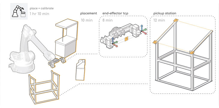
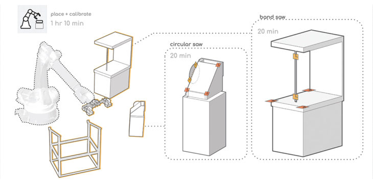
The setup begins with tagging the pieces to be able to trace the elements after fabrication for assembly purposes. After mounting the gripper and placing the tools, calibration starts with getting the TCP of the end effector (planes identified in diagram), followed by the pickup station and the power tools. Once everything is properly calibrated, the operation is the following:
- Grab the piece from the pickup-station
- Go to the bandsaw and cut the 1st piece
- Go to the circular saw and cut the notches
- Go back to the bandsaw to cut the middle and last edge piece.
Assembly
The estimated total assembly time is approximately 9 hours.
The assembly processes consist of 2 stages:
- The production of the base (feet)
If made of concrete total of (2 days)
or
If CNC’d wood base (3 hours)
- Placing the grid
All pieces are accurately placed to their unique locations with the help of Fologram (a Mixed Reality – MR application) and screwed to the corresponding piece. (6 hours)
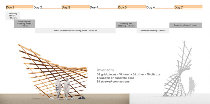
The overall project making from design to the building process has been distributed over a week. The above timeline is sensitive to the amount of processed offcuts; for this structure 18 pieces are considered.
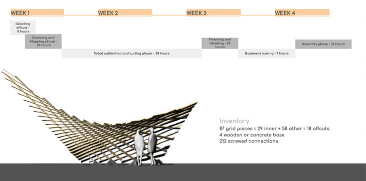
For four weeks proposal, we scale up the model by 1.5, and increased the density. In the end we have 87 grid pieces (29 inner piece + 58 outer pieces). Total raw offcuts material would be 29, 2.5 times connections needed and 2.5 assembly accordingly.
Faculty:
Alex Dubor
Marielena Papandreou
Team Members:
Federico Caldi
?pek Attaro?lu
Wu Yue
Yeo Jeong Kim
