
Table of Contents
- ABSTRACT
- METHODOLOGY
- STATE OF THE ART
- Historically horizontal stacked dry stone.
- Multihalle Pavilion – Frei Otto & Ove Arup & Partners
- Felix Candela thin-shell structures
- Iaac 3DPA 3D printing over wood scaffoldings
- Iaac 3DPA Fiber reinforced earth 3D Printing
- Formwork impact in construction of complex geometries. Rolex Learning Center case.
- Block Research Group Cable-net and fabric formworks for concrete shells
- Peter Zumthor Swiss Pavilion for the World Expo Hannover
- FIBER NETWORKS
- Two dimensional networks
- The Set-up
- Tensioned fiber is a line
- Iterative approach
- Generative approach
- Three dimensional networks
- Inclined Plane
- Ruled Surfaces
- Paraboloid Hyperbolic 0
- Two dimensional networks
- PRINTING OVER FIBERS
- Set-up and calibration
- Fiber amount
- Consolidation stage
- Adherence
- Wet fibers
- Clay addition
- Overprinting
- Motion
- Rotation
- Weight and tension
- Toolpath conflict
- Fiber along the toolpath
- Fiber as temporary support
- Retraction
- Weak points
- The need of mass
- CLOSING THE CELL
- 3D Printed support over fiber
- Along the cantilever
- Across the cantilever
- The Pyramid
- The Vault
- Vault’s slicing problem
- Height adaptive slicing strategy for vault and catenary
- Vault’s Infill
- Adapting the vault’s width to its support
- Adapting the orientation of the vault’s ribs to its support.
- 3D Printed support over fiber
- EARTH TO FIBER CONNECTION
- Wet state of the earth
- Anchoring tensors and adding intelligence to the walls
- Scalability
- FINAL EXPLORATIONS
- 1:10 small-scale prototype
- 1:3 medium-scale prototype
- FURTHER DEVELOPMENTS & TOOLKIT
- CONCLUSION
- BIBLIOGRAPHY
—
ABSTRACT
To deal with the fifth façade, vernacular earth construction introduces different materials to cover horizontal spans. This switch of materials allows the earth to work primarily under compression, avoiding altogether the need to work against gravity and the intrinsic tension that horizontal elements require to be supported.
This research follows the same strategy by using additive manufacturing 3d printed earth over flexible natural fibers under tension to allow horizontal coverages. Different physical and virtual studies were performed with a computationally designed workflow and dynamic positioning of earth and fibers with small 3d-printers and large-scale robots.
The research explores how to introduce 3d printed shells over tension elements while opening the possibility to use temporary substructure networks for long-spanning and low-inclining coverages. Placing over the tensors a network of shells or vaults could be useful to solve wet-stage consolidation and then remove it once dry while keeping the space usable during the drying process.
In order to reduce the total volume and time of 3d printing, spread the compression system of a shell into a bigger area, and reduce the mass of the structural system, several iterations and prototypes were made. Compared to centering and formworks -traditionally used in the construction of vaults and shell structures- this strategy would require little extensive costs, in terms of time and material.
A design approach led by networks that then convert into closing spaces using shells such as pyramids or vaults. Based on this a set of tools was developed with specific slicing techniques that will allow achieving those geometries.
The first studies explore how to print over fibers, define placement and amount, and calibrate and set up printers. Other topics such as shrinkage, movement of tensors, and dry vs wet fiber need to be taken into consideration to ensure correct results. The second part of the research will define a computational strategy for complex networks of tensors and the design workflow to develop walls, ropes, and vaults.
Other topics such as external or internal connectors, scalability, toolpath, and infills were explored and settled up in a set of open files. A pure computational design approach and this set of custom tools generated during the research will allow expanding on further explorations to generate new geometrically complex design propositions.
Additive manufacturing processes allow the optimization of the distribution of the material to an open and liberated form of design. Combined with 3d printing, this method may be able to meet one of the main challenges raised by additive manufacturing in architecture, namely, printing the roof and covering spaces.
METHODOLOGY
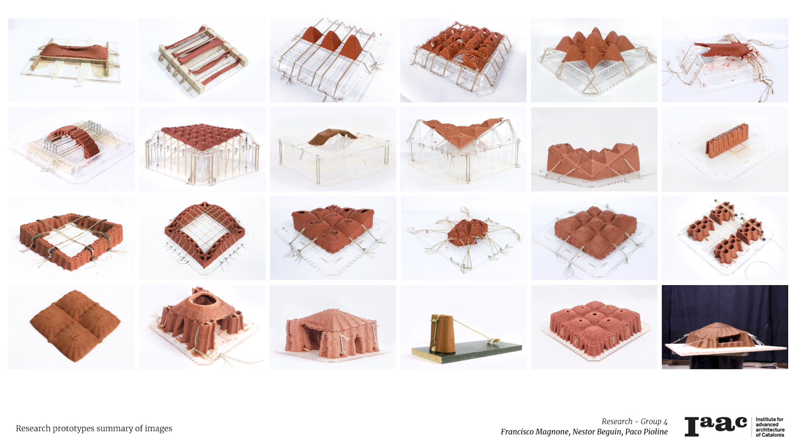
The research is conducted in a physical-empirical manner and follows an experimental approach to fast producing different samples of geometries and understanding their physical conditions. It predominantly evolves through the development of the design to fabrication, with the production of low-scale and medium-scale prototypes that could be later explored as an architectural space.
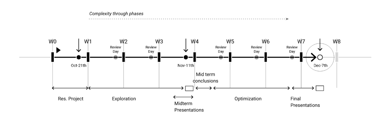
The work was divided into eight weeks of intense work adding complexity through phases:
a) Exploration: Understanding the use of 3d printing over natural fibers.
b) Optimization: Designing workflow and tools, fabrication process, and robotic tooling.
While all geometries are developed using digitally aided design custom workflow -Rhinoceros and Grasshopper-, some of them are tested physically using 3d printers and simulated on a 6-axis robotic arm. A final geometry was developed into low scale and medium scale to ensure scalability.
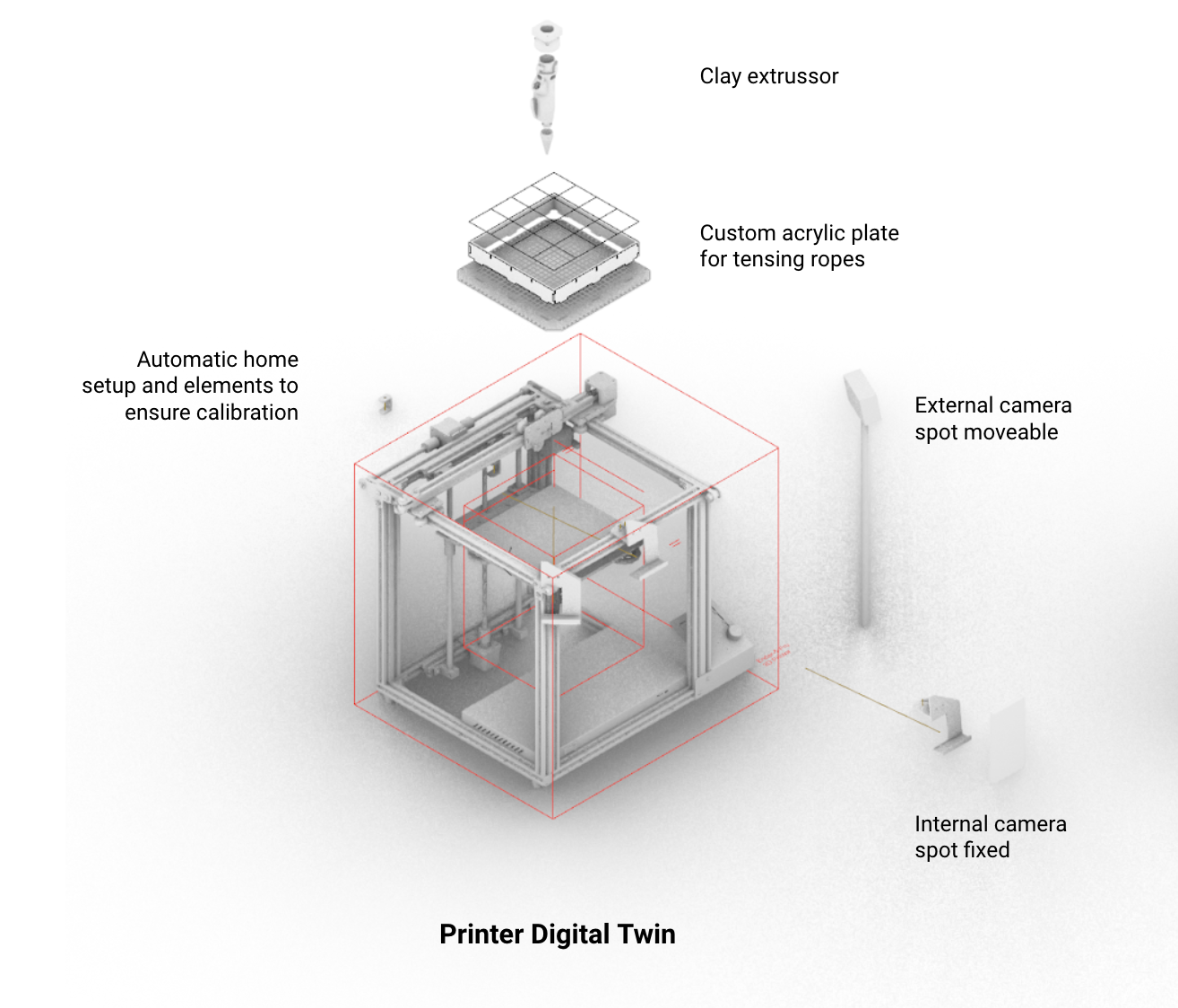
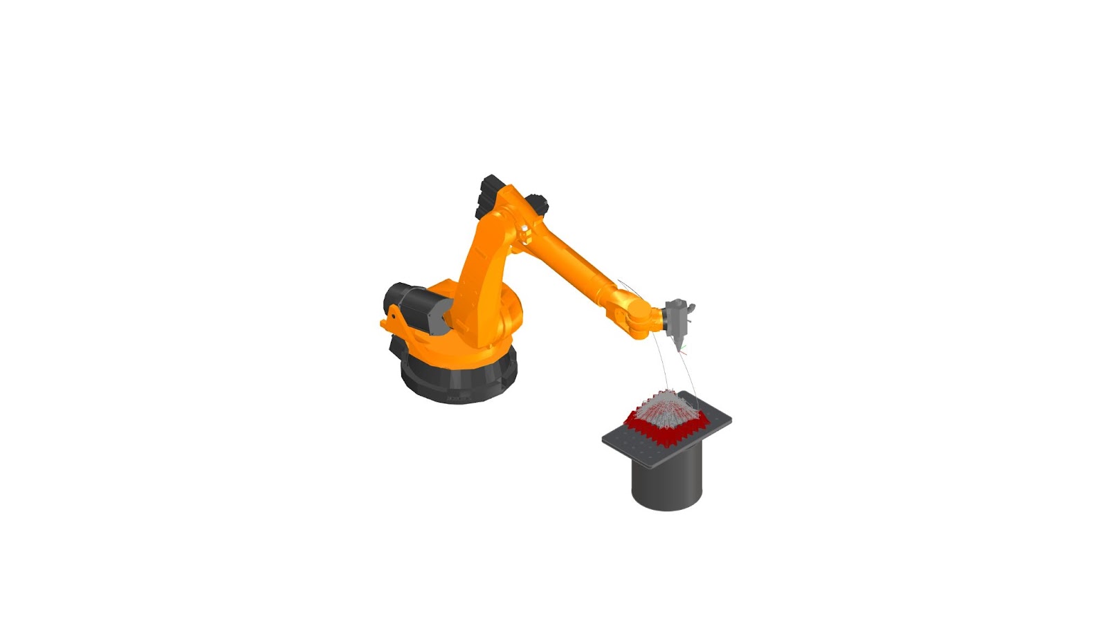
Image of tools used during the research. From 3d printers to ABB or Kuka 6 axis robot arm.
STATE OF THE ART
Historically horizontal stacked dry stone.
A trullo is a traditional Apulian dry stone hut with a conical roof. Their style of construction is specific to the Itria Valley, in the Murge area of the Italian region of Apulia. While the material position is dry and uses small pieces, the distribution of the material in small horizontal layers is closely related to the 3d printer slicing approach. At the same time, the combination of shells into a diverse network of elements presents a smart way of reducing their total height.

Image of Trulli, Alberobello
Multihalle Pavilion – Frei Otto & Ove Arup & Partners
Freï Otto (1925-2015) is a German architect known in particular for the construction of the Olympic Stadium in Munich and his work on textile structures. He received the 2015 Pritzker Prize some time before his death. He has dedicated his career to developing ways to manufacture large lightweight structures with the aim of helping poor people get a roof over their heads.
Otto worked with reversed models where gravity gives the appearance of his experimental building. A little more marginal, it also uses inflated plastic sheets to formalize domes or even polystyrene balls attracted by magnets in order to generate the arrangement of its structural elements.
Frei Otto and the development of gridshells
Felix Candela thin-shell structures
Candela proves the real nature and potential of reinforced concrete on complex laminar geometrical structures. The extreme efficiency in a dome or shell-like shape needed a strong formwork design that was usually simplified into a network of linear elements.
We can see here the big amount of material an complexity needed to achieve thin concrete shell structures
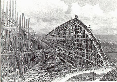
Candela’s use of straight members in formwork
Iaac 3DPA 3D printing over wood scaffoldings
Previous research made in 3DPA already tried to tackle some of the challenges that we faced. Some strong overhangs have been achieved using flexible wood structures. The idea of introducing fibers into clay is already widely present into faculty’s researches, although it is more about inserting them as reinforcement more than using them as formworks.
Also, the “Vault key” problem was already pointed out, being a serious challenge to planar slicing approach, when it comes to close surfaces.
Those models were a serious reference to our design and some experiments below are clearly inspired.
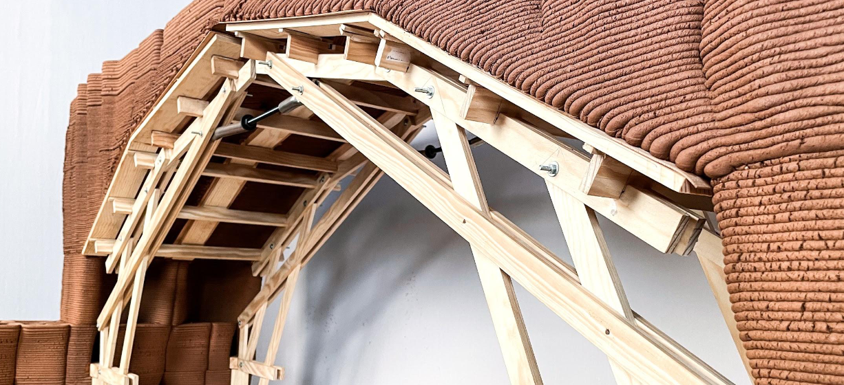
3DPA – Embedded supports for 3D printed earthen architecture
Take note of the piston in between the two structures, that allow the formwork to follow the clay’s retraction.
3DPA – 3D Printing vaults and domes
3DPA – Embedded supports for 3D printed earthen architecture
Iaac 3DPA Fiber reinforced earth 3D Printing
Iaac’s previous research on fibers showcased us how complicated it can become, specifically speaking of the set-up that needs to be put in place. Also, extensive use of fibers seemed to have caused break due to shrinkage. This model shows impressive overhangs, but it did not stand the drying phase.
3DPA – Embedded supports for 3D printed earthen architecture
Formwork impact in construction of complex geometries. Rolex Learning Center case.
“Concrete formwork cost is significant. The cost of formwork amounts to anywhere from 40 to 60% of the cost of a concrete structure”
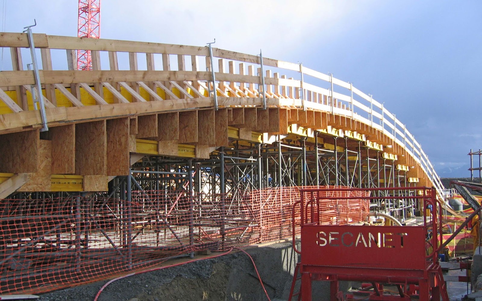
“The large, doubly curved concrete slab of SANAA’s EPFL Learning Center in Lausanne required a specific formwork solution. A smoothly curved surface of 7,500 sqm was constructed in combination with standard scaffolding components, using nearly 1,500 individual wooden boxes.”
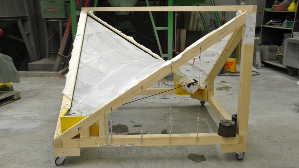
Block Research Group Cable-net and fabric formworks for concrete shells
The project investigates the feasibility of using both large cable nets with a secondary system of fabric shuttering as well as fabric directly as a formwork for concrete shells. Here, we can see how they achieved a thin concrete shell, very similar to Candela’s work, but by reducing the formwork from complex and dense wooden assembly, to lightweight cable network.
As a example of poured material over fabric networks, this project has been one of our main source of inspiration.
Cable-net and fabric formworks for concrete shells
Peter Zumthor Swiss Pavilion for the World Expo Hannover
Swiss Pavillion is designed using same-size wood beams that are separated and stacked without the addition of any glue or screws. To ensure stability, the walls are connected with tension rods and steel springs working by compression and friction only. Binding by straps and steel springs allows the dimensional change of wood to dry out and is consistent with the temporary nature of the building.
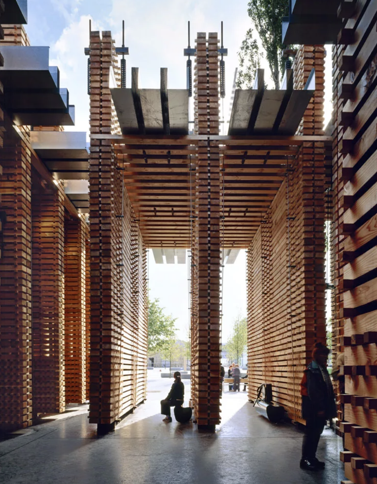
Swiss Pavilion Image by Roland Halbe
FIBER NETWORKS
Two dimensional networks
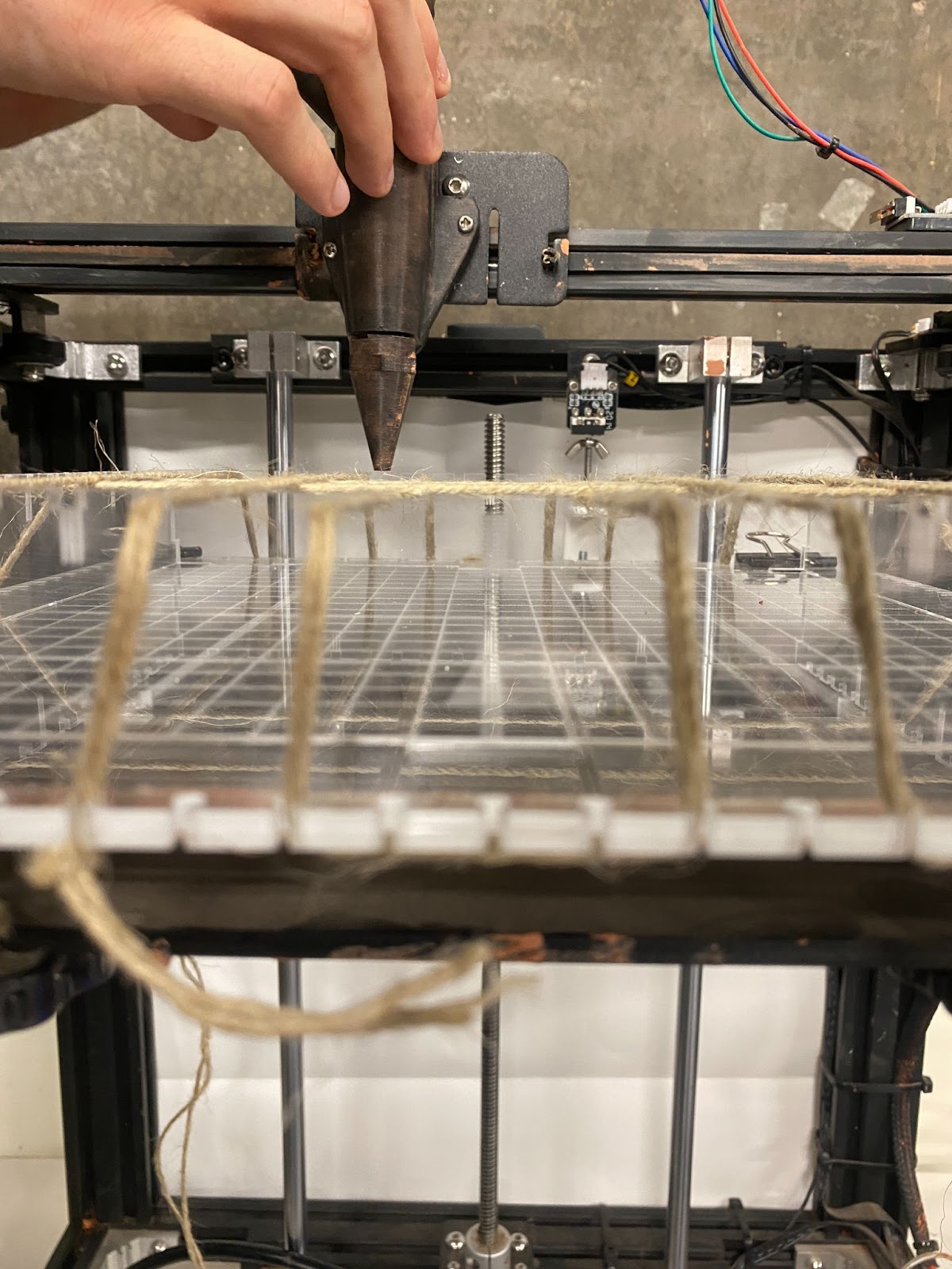
The Set-up
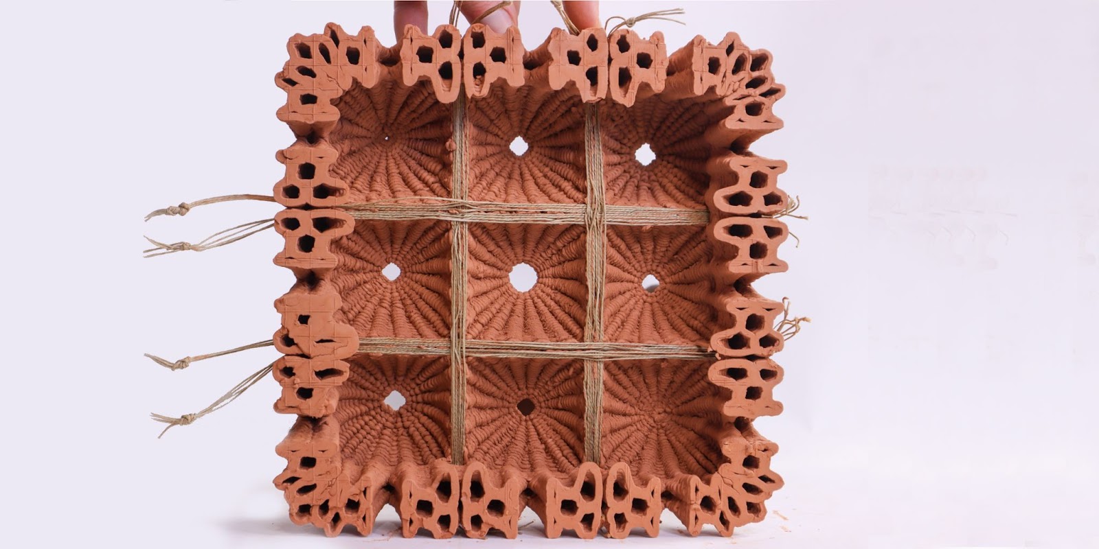
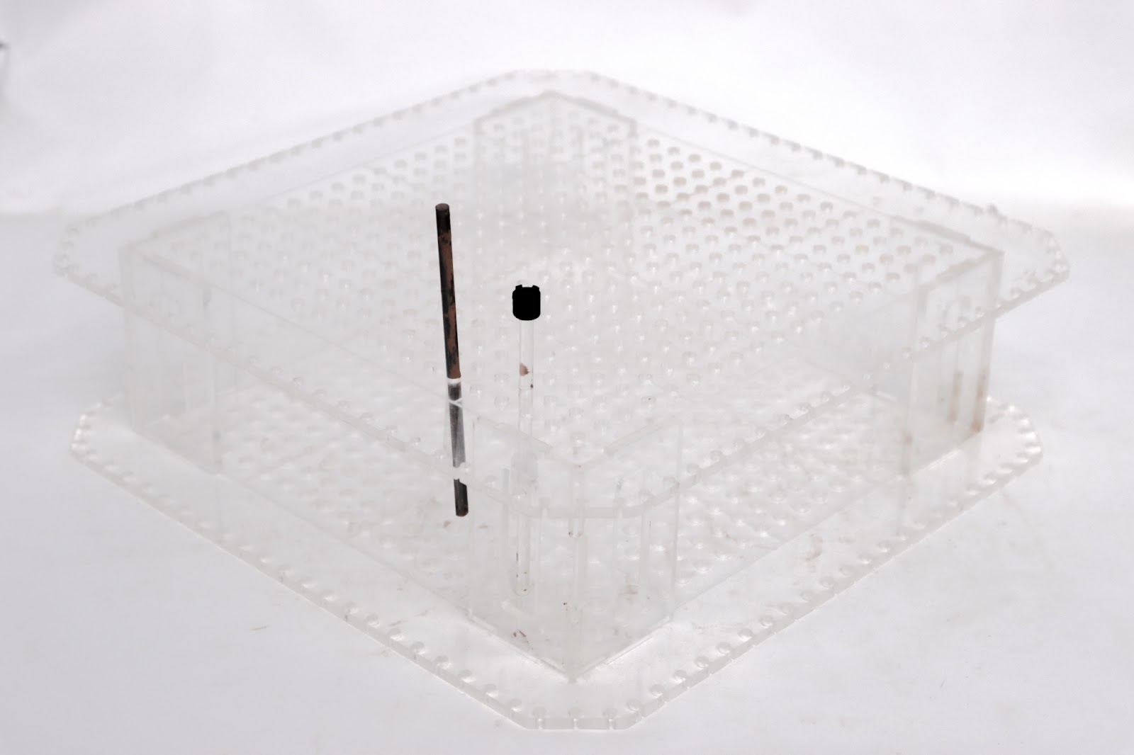
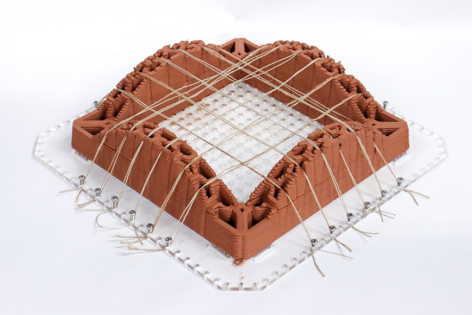
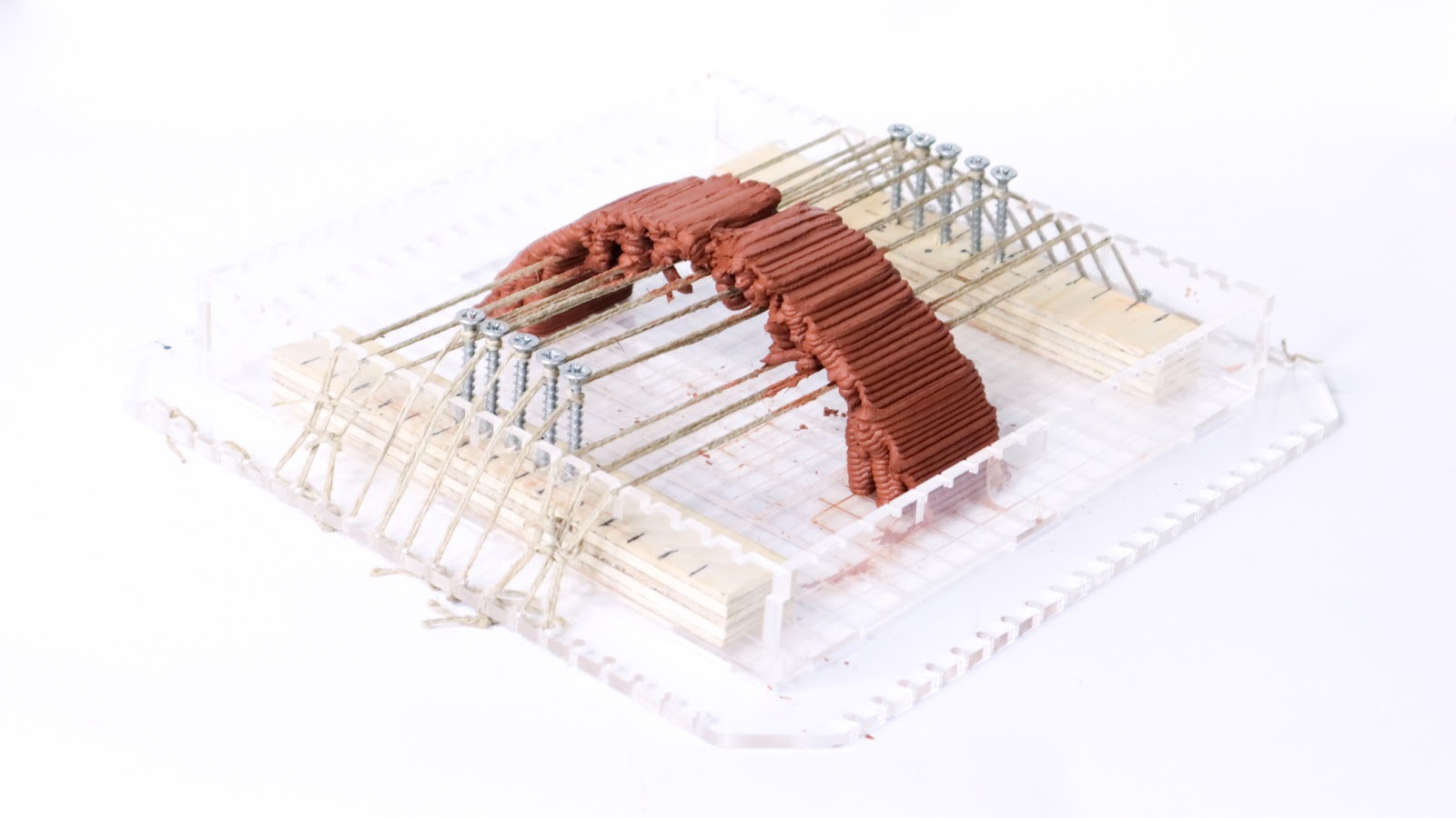
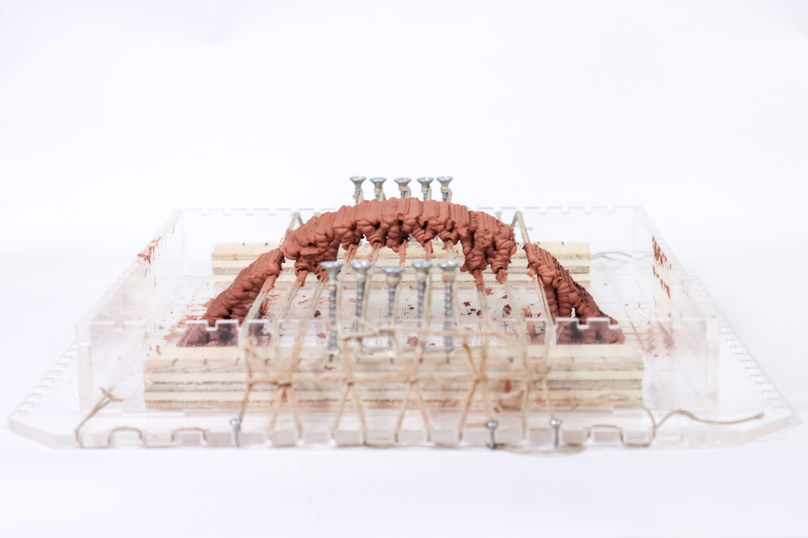
In order to explore those networks we built an acrylic plate that matches the size of the desktop printer.
The plate has holes on the edges to allow us to place and tense the fibers manually and fast. This is really important to be sure that we can place them precisely also, as we can know exactly where we are going to print thanks to the marks engraved.
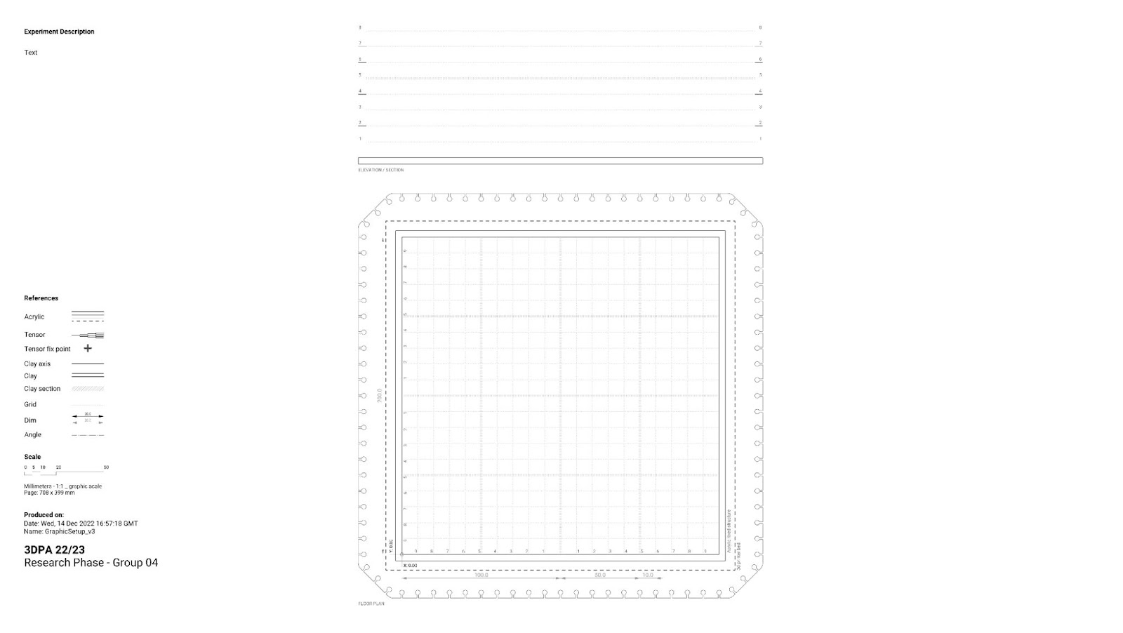
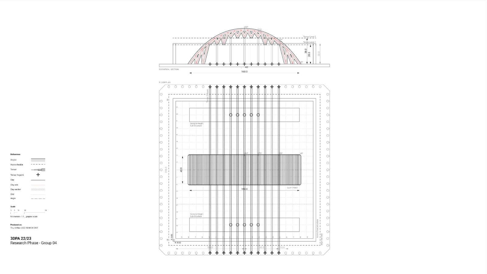
Graphical setup, recreating the physical model we cutted ou acrylic. This model will follow us all along the 1:10 Scale research.
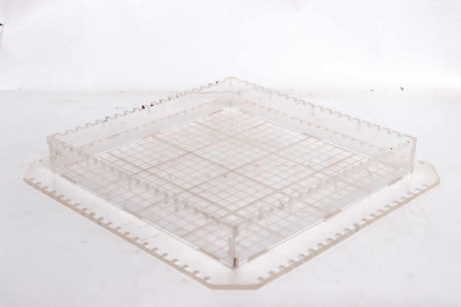
Planar setup, with 30 mm walls.
Tensioned fiber is a line
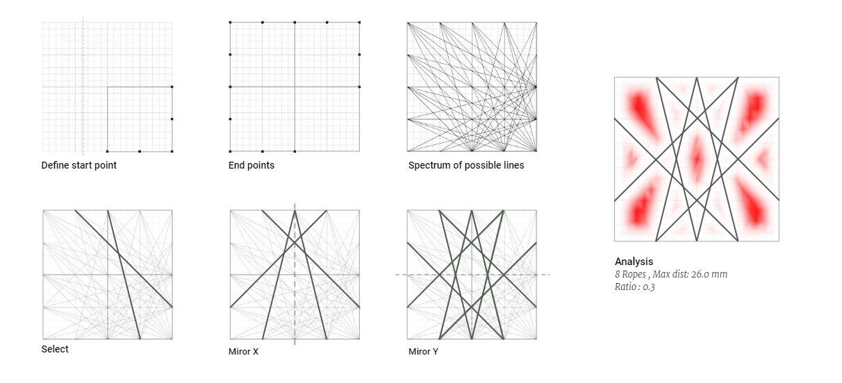
A tensed fiber can be discretized as a line. This geometrical element serves as a base in mathematical models and can be generated out of any kind of point organization.
Iterative approach
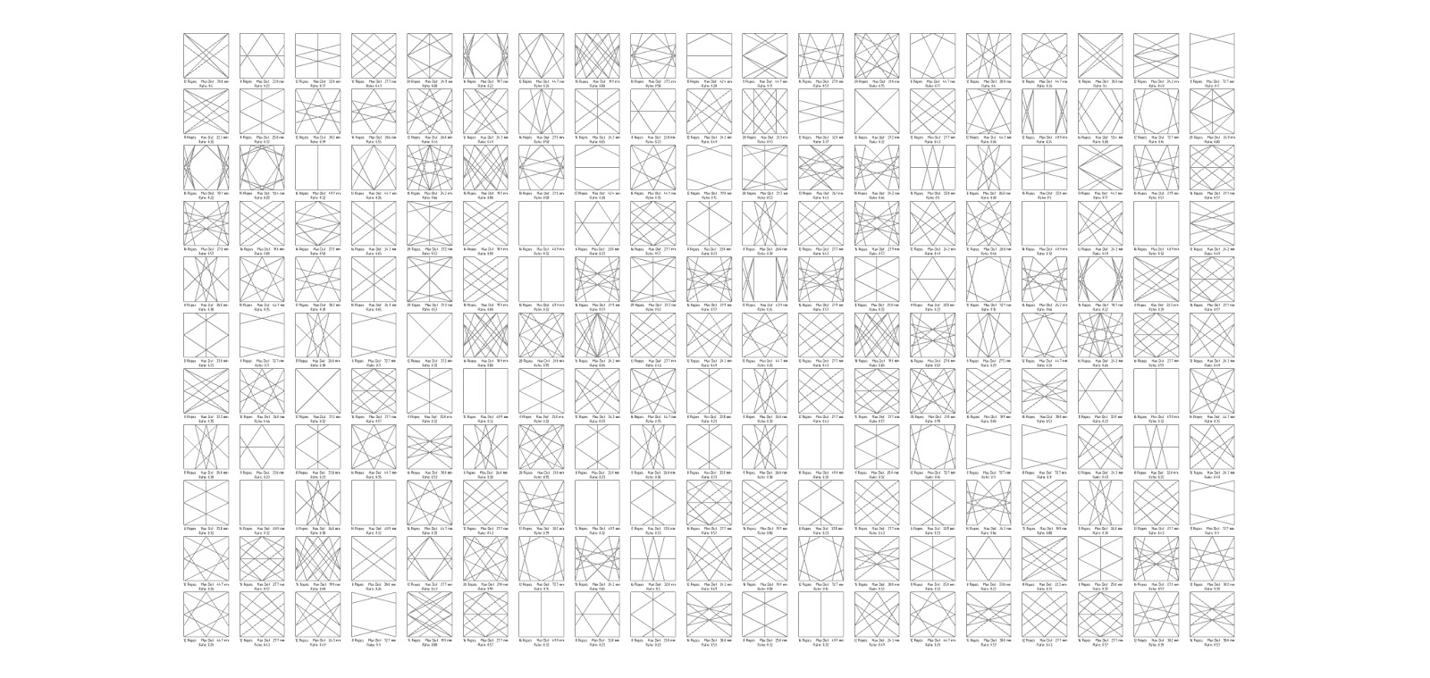
By multiplying line patterns in a square grid, we can have an overview of the diversity of patterns and regions it can generate.
However, to be able to pick one from another, we need to find a way to compare them with each other. In order to do that, we created a graphic algorithm that shows the maximum distance between the generated edges and the center of the resulting geometrical shape. Also, fewer ropes requires a minimal set-up, making it more efficient. A good geometry would then be represented by a minimum amount of fibers for a minimum distance between edges and the shape’s center.
Generative approach
Knowing that we know all the parameters that we need to look at for an efficient grid, we can create a generative algorithm that will try to find and sort the most efficient geometrical patterns.
Three dimensional networks
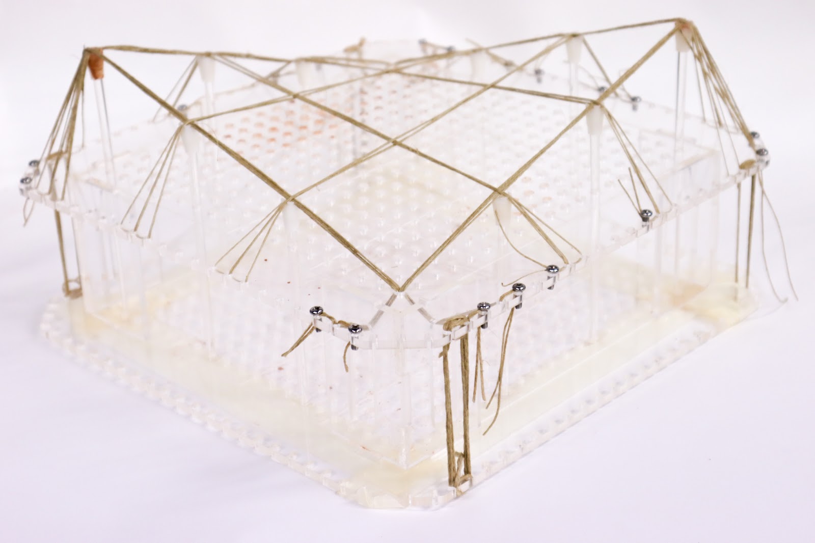
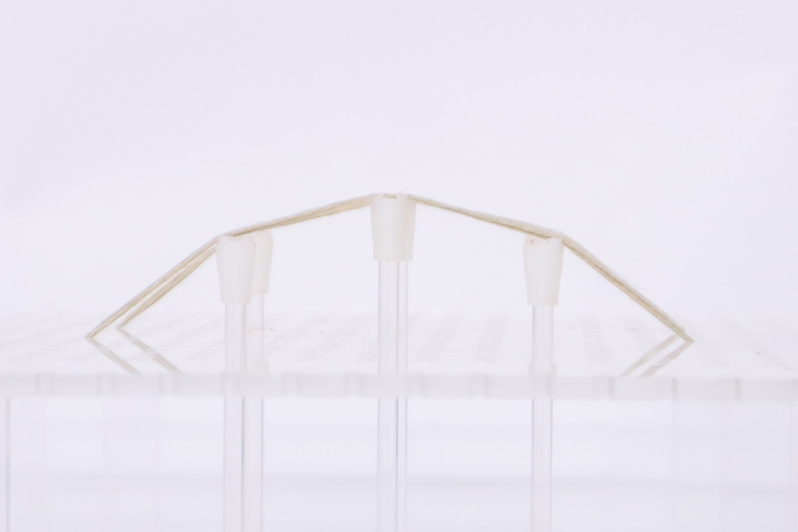
Elevated Set-up that allows pole placement..
By introducing poles into our setup, we allow the pattern to get a third dimension. The third dimension allows us to enter into the tensegrity world. The fiber has a better tension and the resulting shape is more suited to resist the compression forces that work well with clay based materials.
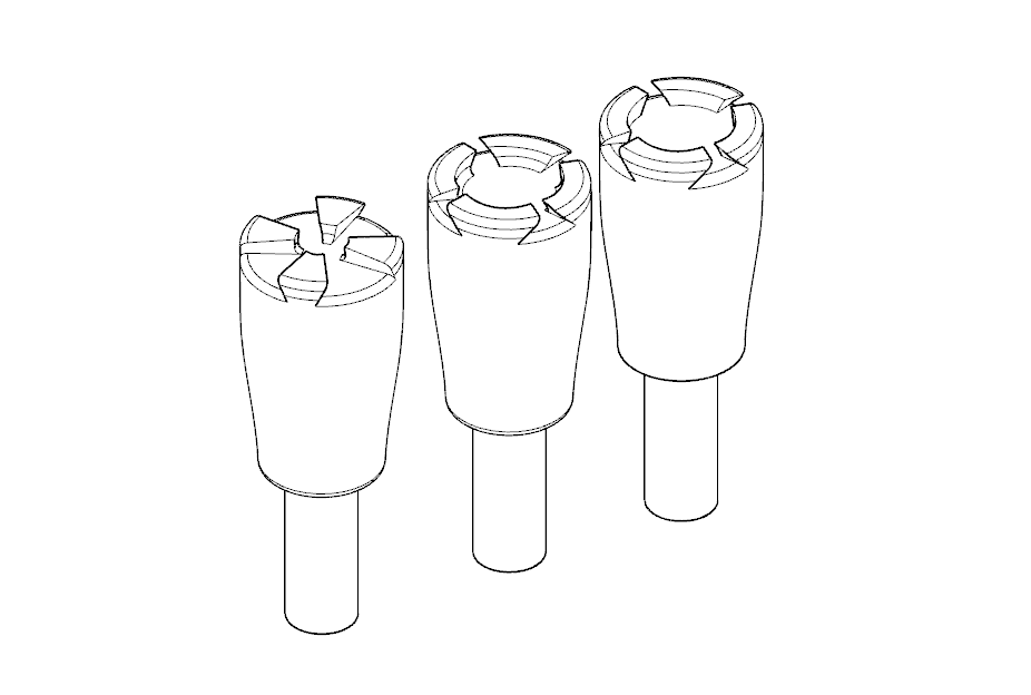
3d printed pole heads prototypes.
Inclined Plane
By adding different levels of connection to the fiber, we can create inclined planes to support the 3D printed toolpath. Specific geometries can now be realized and the printed results can now start to have structural properties related to geometry.
Iterations of inclined planes geometries.
Inclined plane geometry. The inertia helped to get the print finished. Also adding weight on the border. Also did help to place an extra fiber in the center to support buckling punctually.
Ruled Surfaces
If we start from the statement that fibers are straight lines. Any ruled surface should be able to be replicated with a network of fibers and therefore, be printed over.
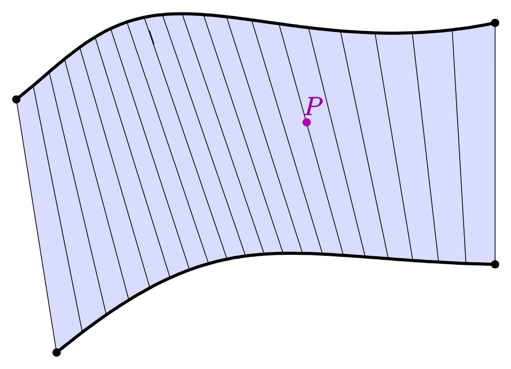
“A ruled surface can be described as the set of points swept by a moving straight line.”
Paraboloid Hyperbolic
We decided to push the research with this specific compression-efficient ruled surface. Also used in Block research Group’s experiment mentioned in the state of the art. This specific surface allows us to keep going into this square-based set-up that is well suited for the size of our desktop 3D printer, our main tool.
Also, this shape allows us to integrate all the setup frames into walls that we can print, this a huge advantage concerning the time you need to set things up.
PRINTING OVER FIBERS
Set-up and calibration
When using multi-material geometries -from 3d printer to 6-axis robots- dividing print in steps and ensuring a secure approach of the nozzle to the geometry is needed. This setup involves the design of custom physical tools for calibration and digital toolpath for approach and going away from the object.
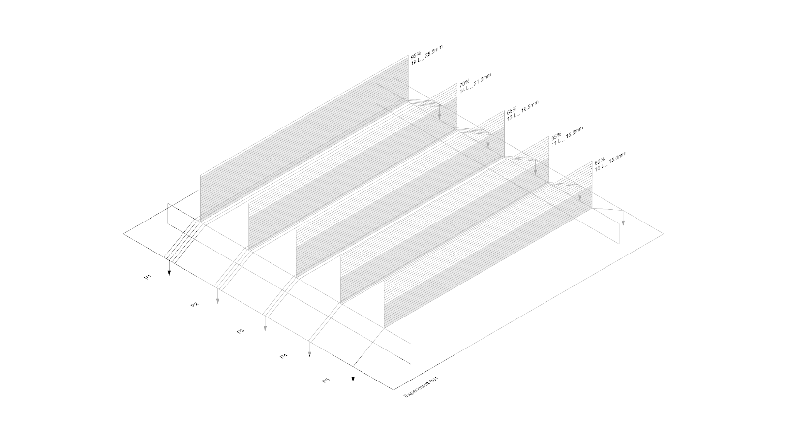
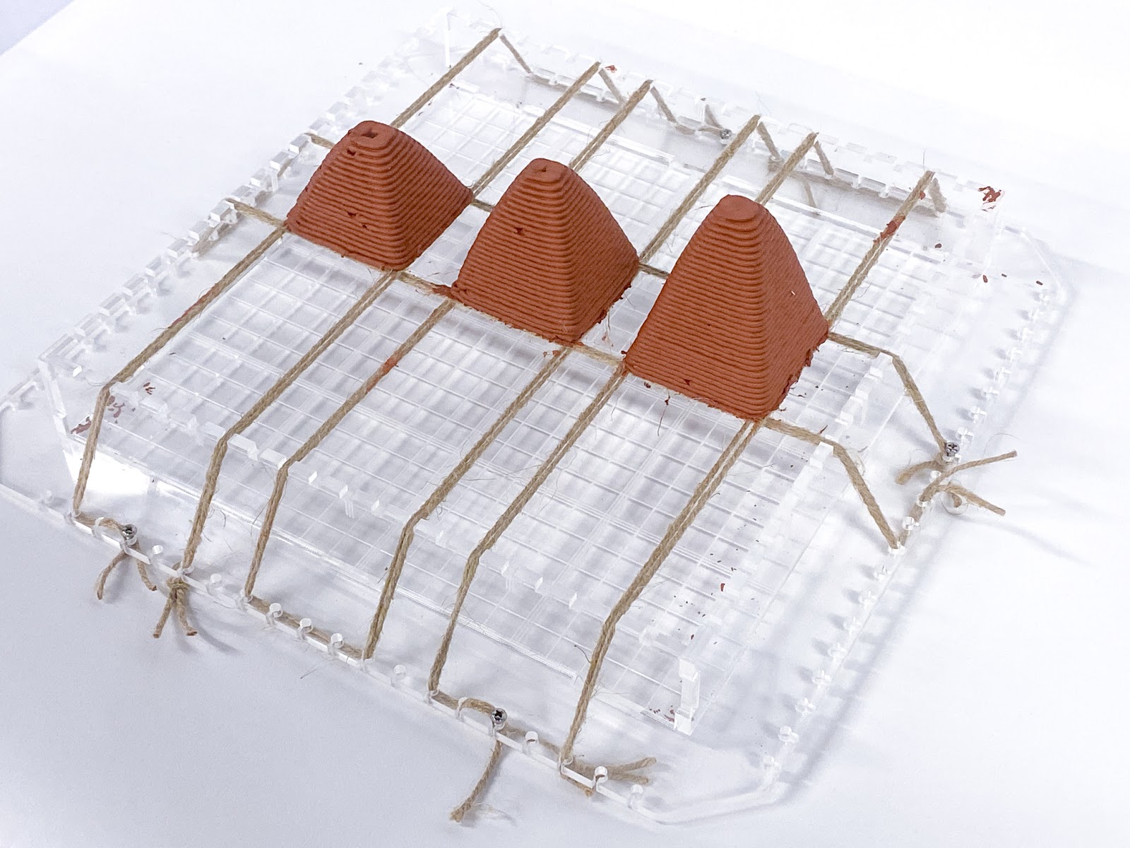
Fiber amount
To understand the relationship between the number of fibers and the printing quality, a simple test was run trying to print a vertical surface over different fiber widths. The quality of the print increases according to the number of fibers, while at the same time more fibers take more time to set up. A bigger amount of tension elements below the first layer reduces visible buckling and movements of the print globally.
Hence, a good mathematical relationship between those is to set up the same fiber width as the print width. It has been seen later that more fibers actually help to fight imprecisions between digital and physical models.
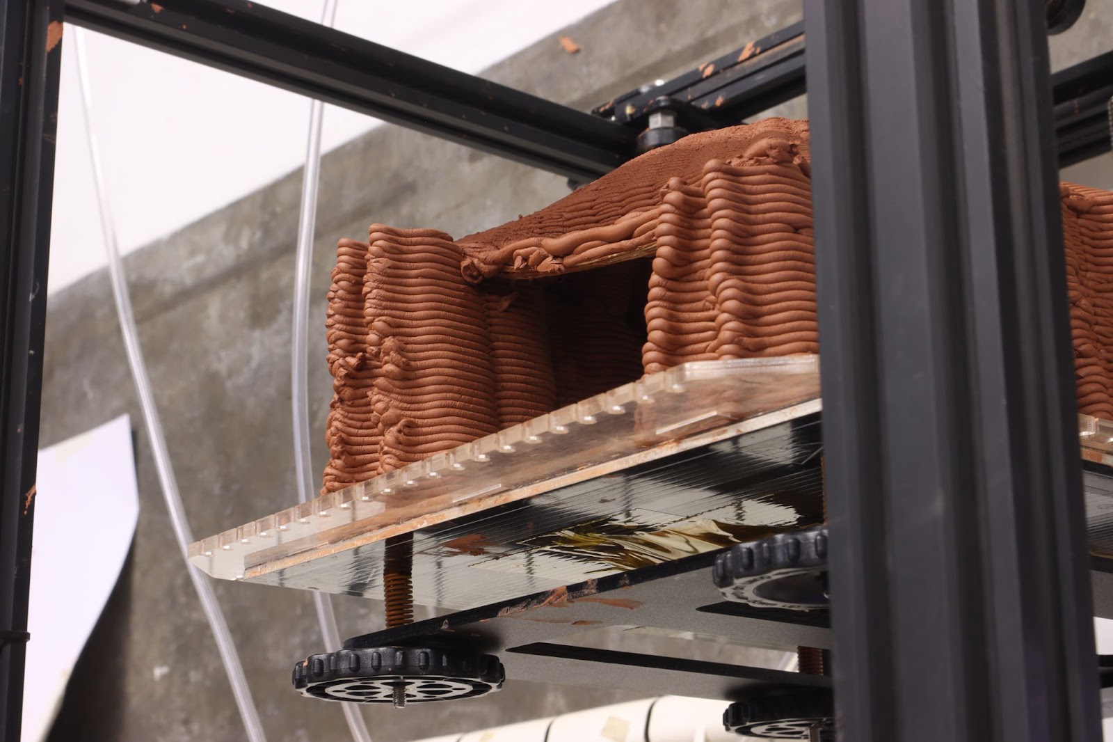
Consolidation stage
An important aspect of additive manufacturing with wet materials is understanding the stages from consolidation to final dry state. Earth 3d printing has a consolidation stage in which the mixture is still not fully dry but acquires basic structural properties to support the next layers. The research focuses on different explorations on this period of time trying to ensure a final consolidation geometry.
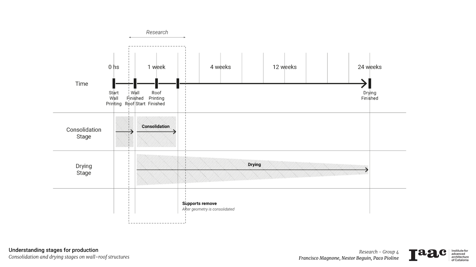
Understanding stages for production. Consolidation and drying stages on wall-roof structures.
Buckling problems from wet materials could present conflicts to achieve consolidation.
Adherence
Different techniques are applied to ensure adherence between the first layers to tensor elements. They include independently or together:
Wet fibers
Fibers bind better together when they are wet. They are easier to set up and increase adherence to the clay, the latter will melt to its contact and they’ll both mix up, increasing material homogeneity.
Clay addition
Once fibers are wet, adding some material along them will also increase the first layer’s quality by creating a strong binding.
Manually adding clay to fibers to ensure binding.
Overprinting
In case the two first cases are not enough, it is good practice to repeat the first layers of impression in order to provide a good clay base for further printing. It will maximize the surface of connection between the fibers and the clay.
Motion
Rotation
Multiplying fibers will help to avoid rotational motion, a consequence of the circular section of the fiber itself. The fibers having only a connection point also allow such kinds of unwanted motion. This can happen either in the first layer, where the material repartion is not equilibrated enough or in further printing, if the center of gravity of the print over it gets too far away from the fiber’s center.
Example of multiple layer printing and detachments.
Weight and tension
One of the findings of this research is to understand motion given by tensor elements.
Working with tension elements needs to consider deviation distances from theoretical lines to real geometry. The more load you add per tensor, the more tension you need on each fiber or cable to reduce the deviation.
During printing the fiber will act as a spring, making sure that the printing level is more or less at the right value to support the next layer. Additive material placed will push down the fiber, which will push back the material and help the further layers to have a good adherence between each other. As stipulated before, overprinting can help stabilize the model as it will ensure a good mass-to-tension relationship.
There is a displacement that could be anticipated. In order to compensate for this movement we duplicate or overprint the first layers.
As we see in this detail, this motion or deviation is caused mainly by:
1) The lack of tension on the fibers
2) And the anchor point that could shift because of the wet state of the clay

Toolpath conflict
The fiber connector must be placed precisely, if too high, there is a risk of the fibers to collide with the nozzle head. If too low, the first layers will not bind. Being too low and overprinting is then a safer approach to avoid any accident.
Doing a first dry run at low speed also help avoiding mistakes. Fiber placement requires a very precise coordination between the digital model and the real setup.
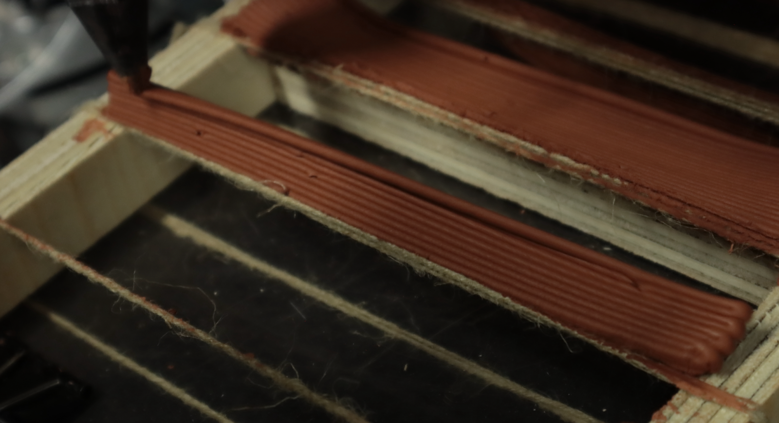
Fiber along the toolpath
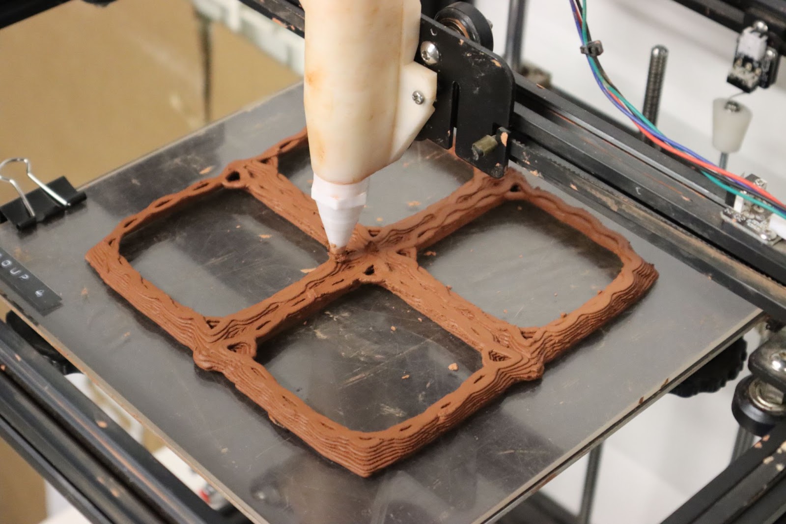
One strategy is to place fibers along the toolpath of the first layer. In that case the fiber network is the base guideline to the entire toolpath and geometry. This approach help to be precise with placement of the fibers and the needed width of it. As the digital model can provide clear plans to the setup.
3D printing an infill over fibers.
Fiber as temporary support
Another way is to place fibers across the toolpath in order to provide punctual support and help the clay’s buckling.The material then uses more the fiber formwork as a local rest support than an actual temporary substructure.
Retraction
In clay 3D printing, when different materials are introduced. There is a geometrical conflict during the drying process. Clay and rope don’t shrink at the same speed, creating cracks.
Weak points
The angle and over the fibers always represent a stronger challenge during shrinkage
10% shrinkage on the extremities disconnect the clay and the fiber set-up.
The weak points are often the junctions between elements, close to the fiber itself. Overprinting the first layers will help to increase shrink resistance where the fibers are.
The need of mass
To avoid this, the first solution is to apply more mass in the weak points.
CLOSING THE CELL
We have reviewed above the different kinds of geometry that can outcome out of specific fiber organizations. However, those geometrical shapes still need to be closed and joined in order to create a tangible surface. In Block’s experiment, they use fabric to pour concrete over. For the purpose of this research, we wanted to try to close the surfaces using rope and clay only. The precision of the 3D printer would in that case help to place material in a way that allows us to close those shapes properly without any external material requirements.
3D Printed support over fiber
Cantilever can be closed using formworks, which can be also 3D printed. The downside of this technique is a huge amount of material, which also requires extra printing time. However, by placing a fiber support at a specific point of the cantilever, we can level the placement of these printed supports to the maximum point where they are needed. The placement is then optimized, material and printing time becomes more manageable.
These temporary supports are there to help the wet state of clay to stay in place while the material properties are slowly changing.
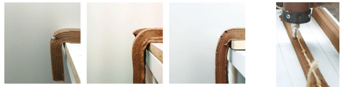
Along the cantilever
By placing fibers along the cantilever, it is possible to create temporary supports that will allow arches to stand. These supports have as a function to stand while the material dries and could be removed afterward, when the arch would be self standing.
In that case , the size of the fiber and the shrinkage of the overall piece stopped the two parts from merging with each other.
This concept is promising to fill small gaps in the print, it could for example allow to introduce windows and door openings. The wood pieces usually placed creates shrinkage problems and cracks hat fibers would sove. This would still need to be reinforced afterwards however.
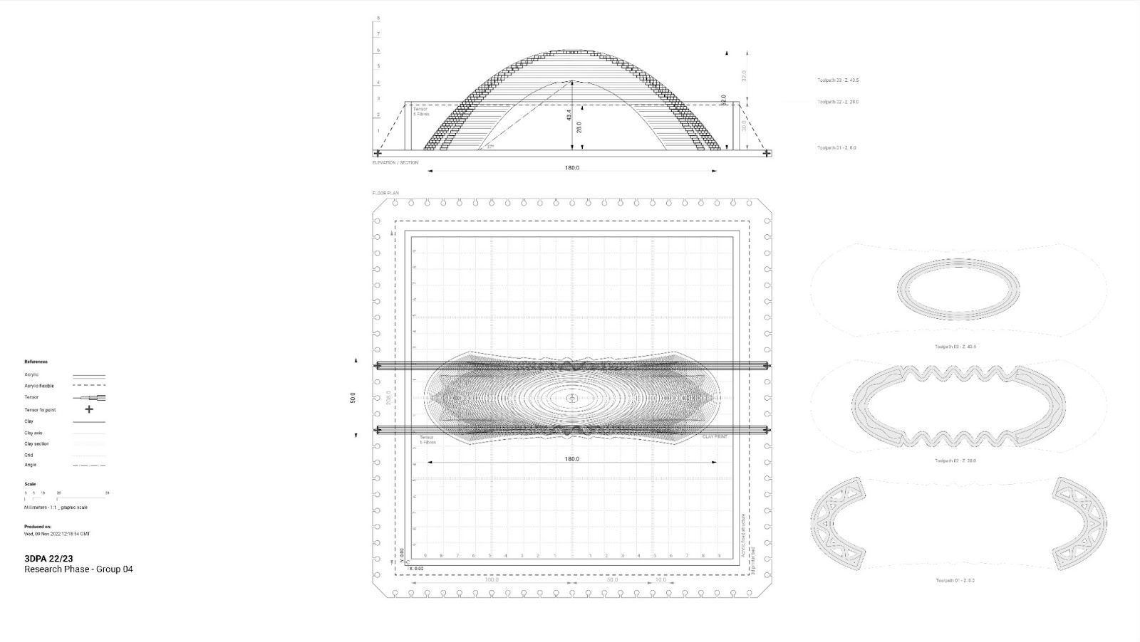
Plan and section of 3D printed support along the cantilever prototype
Across the cantilever
It is also possible to create support using fibers placed across the cantilever, the amount of support needed is reduced because the fibers can be placed very close to the shape, only the last layers have to be printed and it maximizes the surface area of support to help the pieces connect.
However, this formwork is quite hard to set-up and we faced a lot of rotational motion because the center of gravity of the supports were changing all the time due to the printer’s motion.
Also, during shrinkage, havegin fibers placed in a direction that is not the one of the shrinkage forced the pieces to crack between each other, showing a lack of reinforcement. It is possible to see the shrinkage direction in the picture with the fiber’s tension direction.
Plan and section of 3D printed support across the cantilever prototype
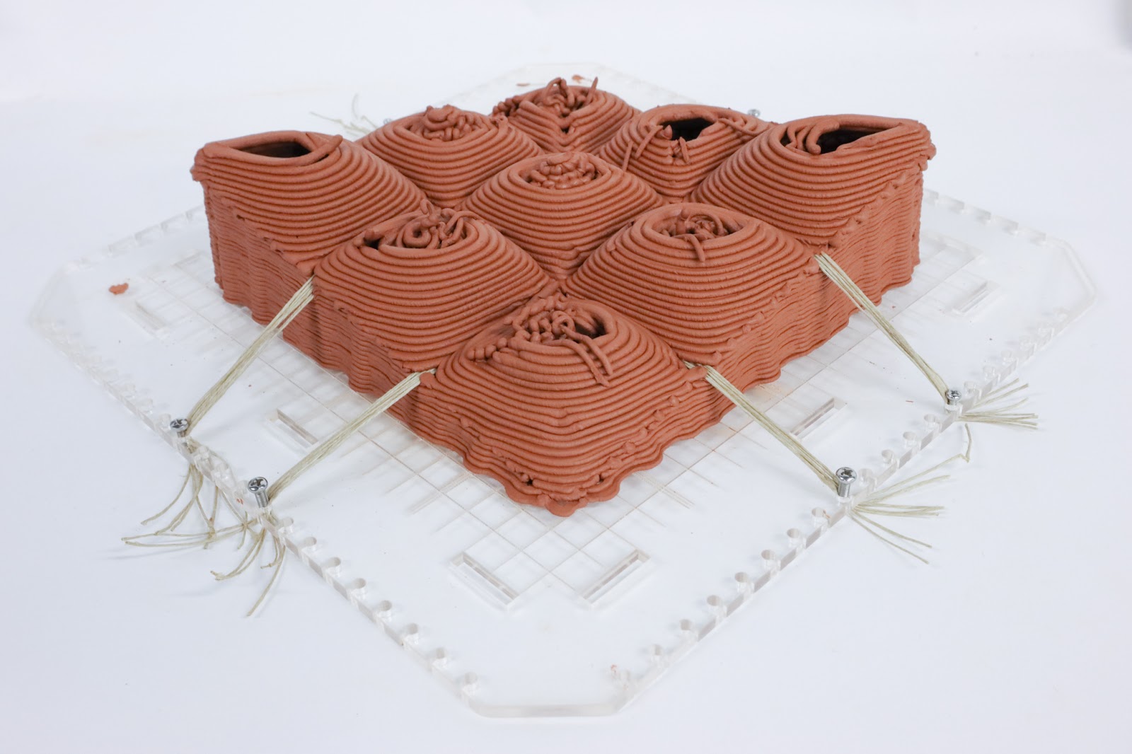
The Pyramid
To close a specific network of curves using a system of vaultlike structures, you need to increase the height in order to reach larger spans. These structures need to act the maximum possible in compression in order to maximize the efficiency of the material. In that case, pyramids are the easiest way to go. It is a gradual offset of the shape, each offset being incrementally leveled. This ensures that each layer sticks with the one before. This technique is very similar to the one that was mentioned in Trulli, above. 3D printing in that case works like a stacking of material.
Pyramids, have specific height, according to their areas
They can respond to very complex geometries without difficulties
Generating openings can be parametrically controlled as they are very predictable geometries.
Plan and section of network of pyramid prototype.
Some failure happens on the edges but the overall shape stands up. The planar surfaces buckle.
However, structurally speaking, they are not the most effective, straight lines are weaker in the case of a plastic structure as they lack inertia, even on good models we could see a large amount of buckling that could maybe not sustain larger scales.
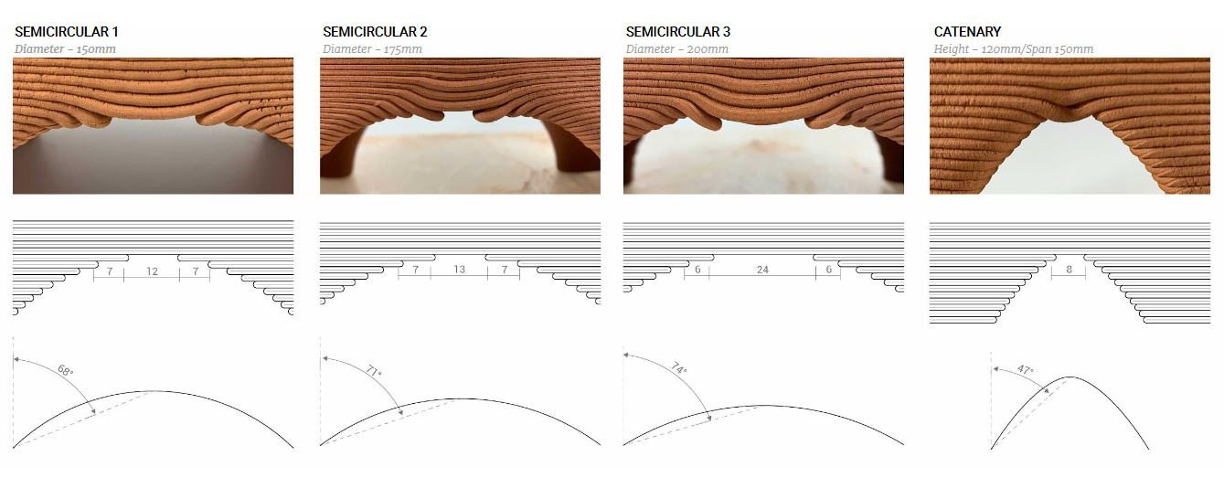
The Vault
Vault’s slicing problem
The vault has a better inertia than the pyramid, its shape is a compression only geometry that is an optimal shape for a material like clay, wet or dry. However, when it comes to 3D printing, the vault faces a slicing problem: its inclination is not stable. The inclination of a vault gets suddenly higher in the end, therefore, layers of 3d printing do not connect and the print will fail.
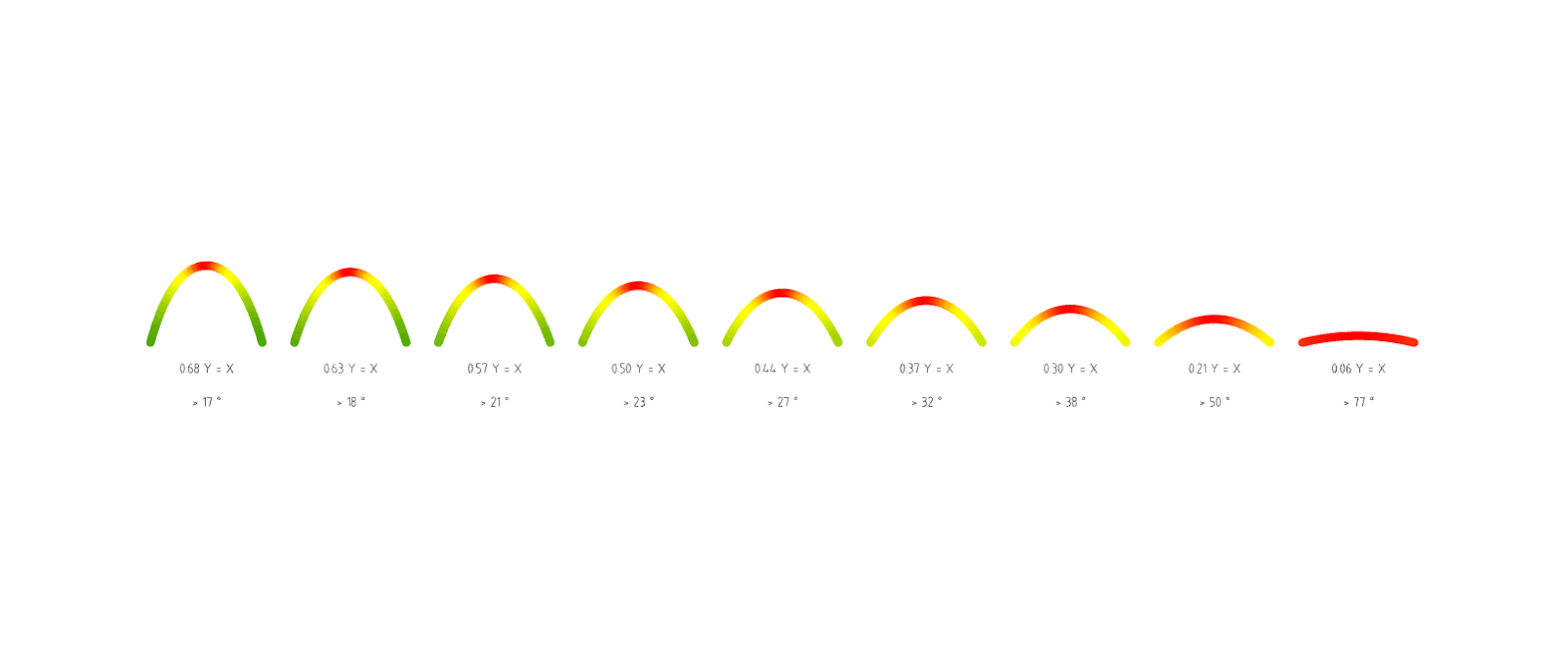
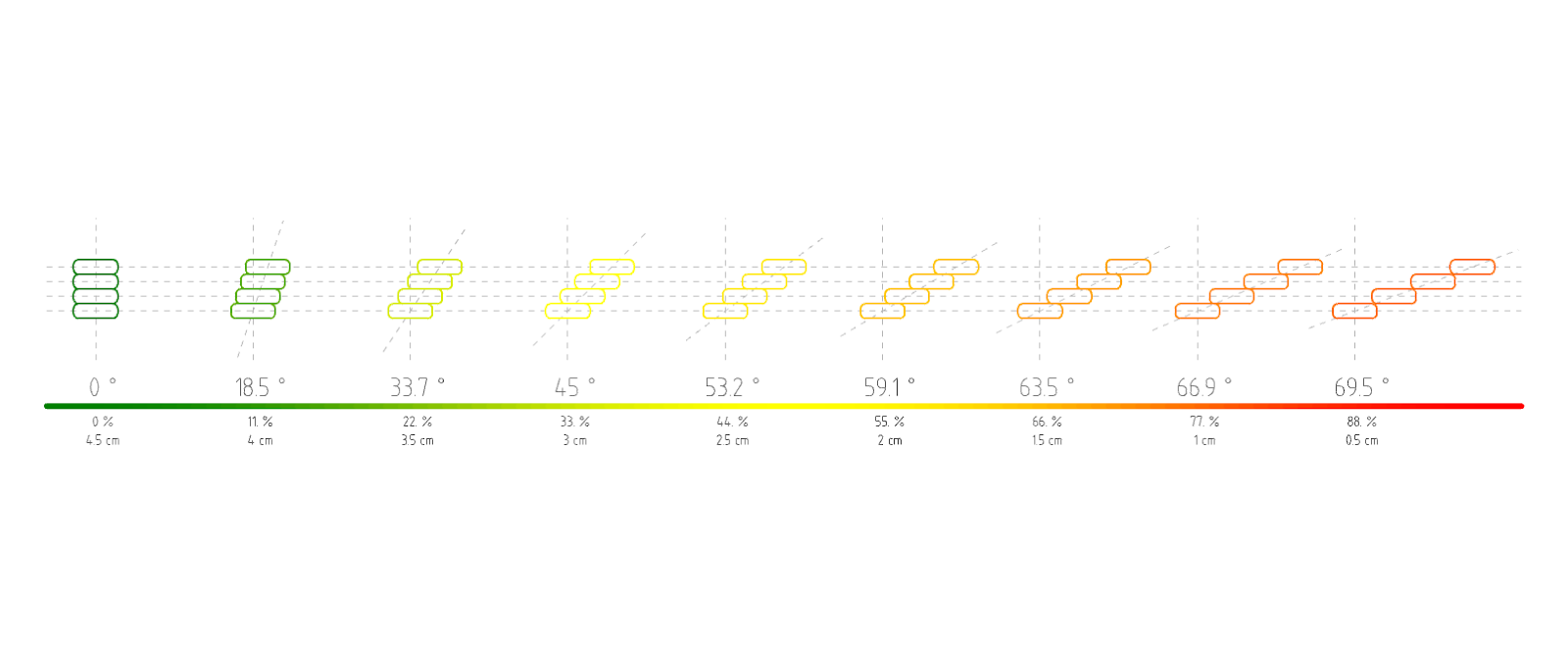
In this graph it is possible to see the connection of layers. In red they don’t overlap, in yellow they don’t connect very well and in green it is printable. It is possible to see that it is really hard to make a printable catenary without making it extremely high.
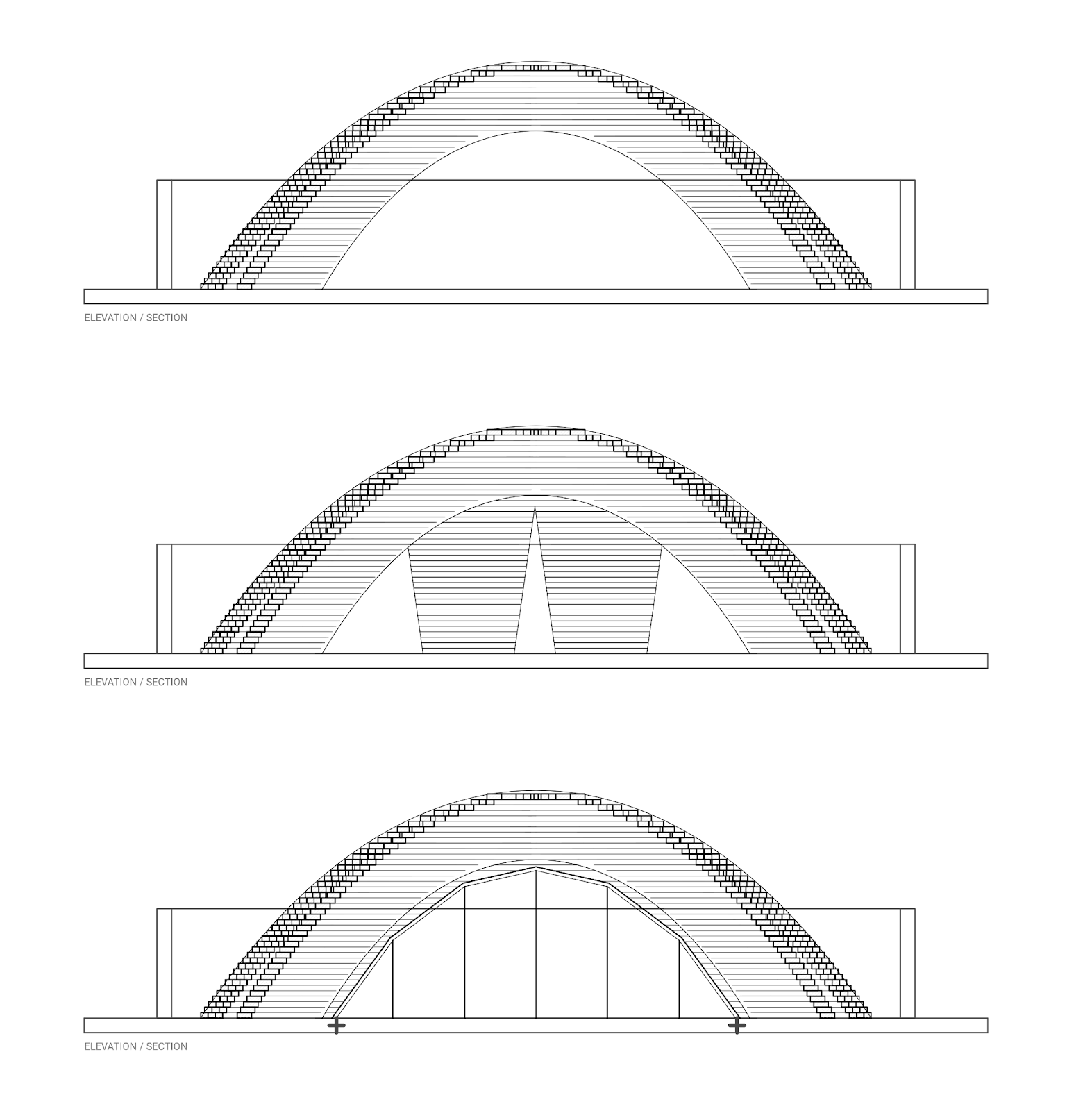
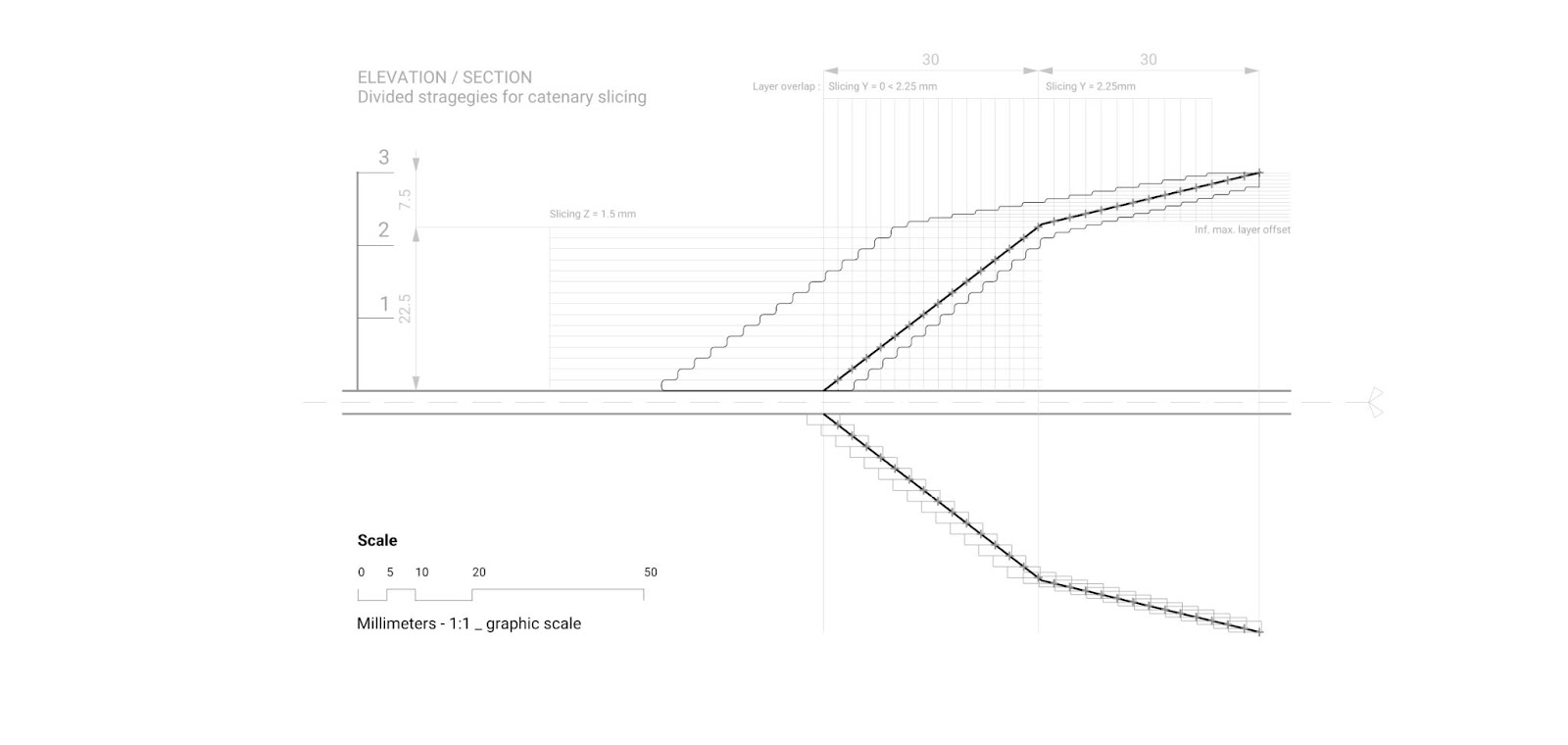
Height adaptive slicing strategy for vault and catenary
To face that challenge, a strategy is proposed hereby, the catenary guide curve of the vault will be analyzed and divided in two parts. The first one will be divided by layer height, the second one by layer width. This is to make sure we optimize the weight of the vault in the right place. More precision about the process has been added to the toolkit at the end.
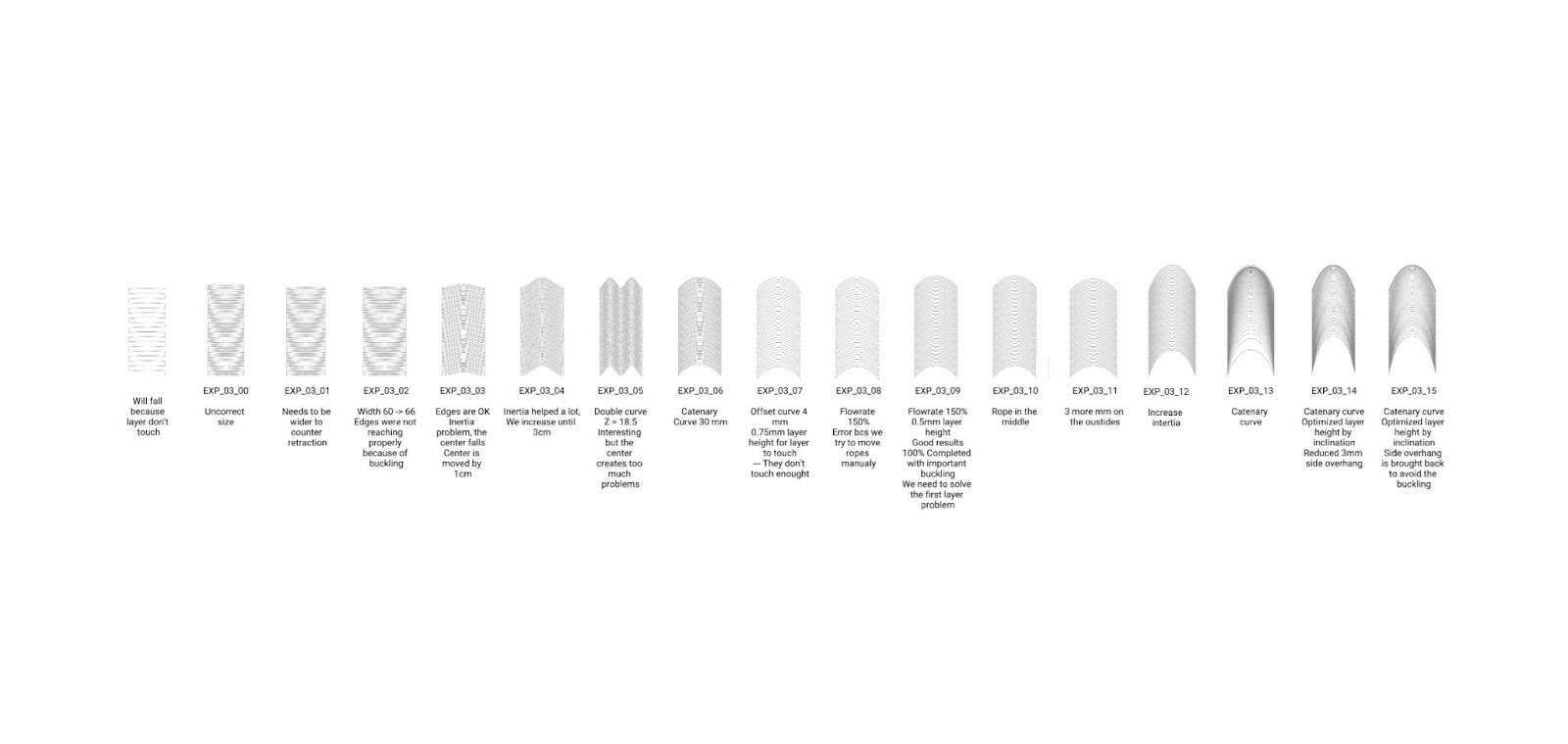
Even if the buckling is high, the layers are connected to one another.
Vault network without adaptive slicing, fails when the layers don’t touch each other anymore.
Vault network with adaptive slicing,there is an obvious over extrusion but the vault could be closed.
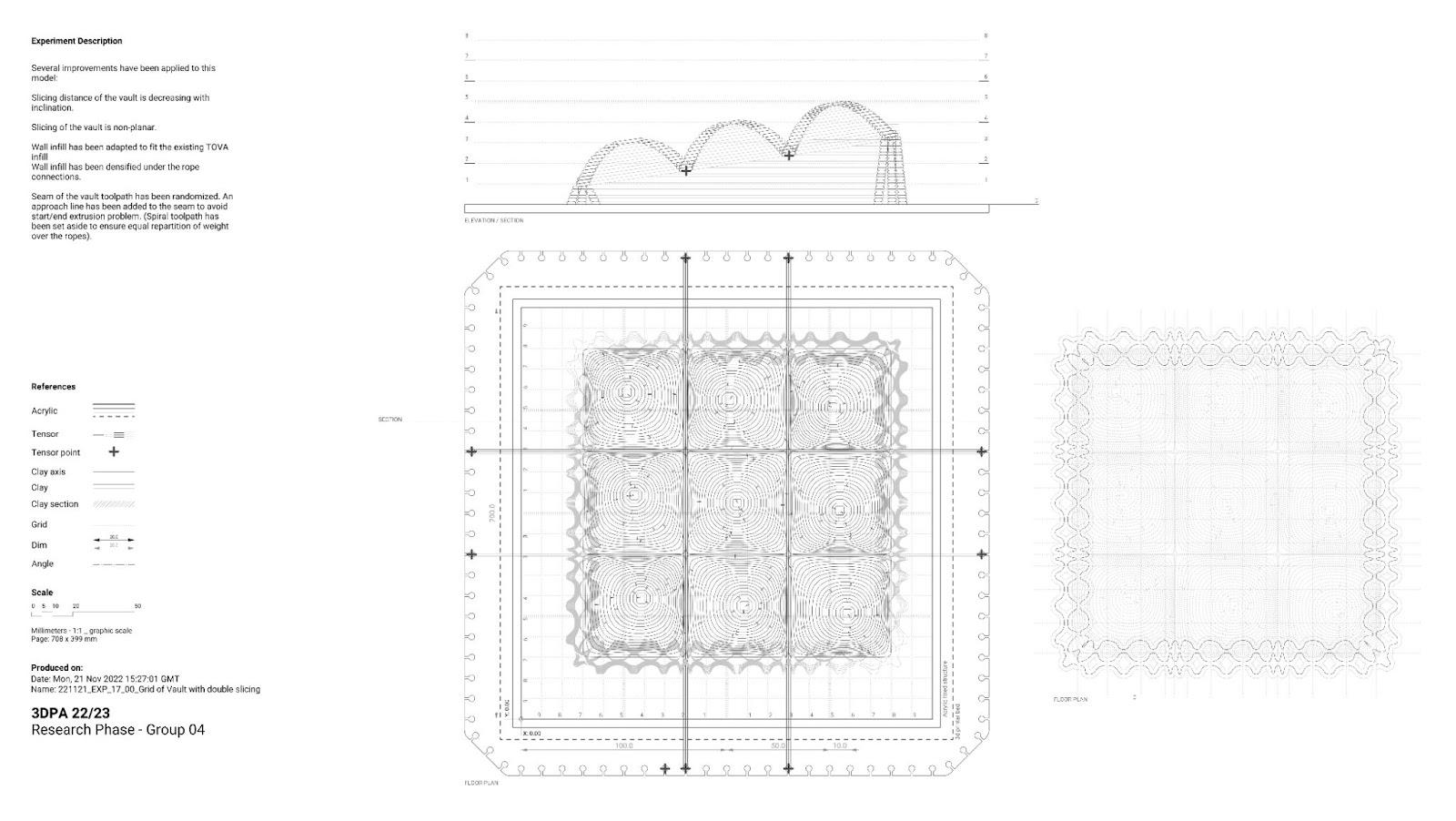
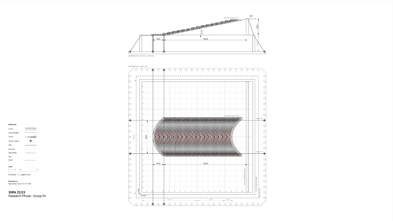
Plan of variable slicing vault prototype. Notice the random approach line on each layer of the toolpath
For the success of this experiment, a random seam had to be applied. Otherwise mistakes of print amplify along the vault and failure is unavoidable. On the drawing above it is possible to see an approach curve that is preventing any mistake of the printer during starts and stops operations, as it would be fatal to the vault.
Vault’s Infill
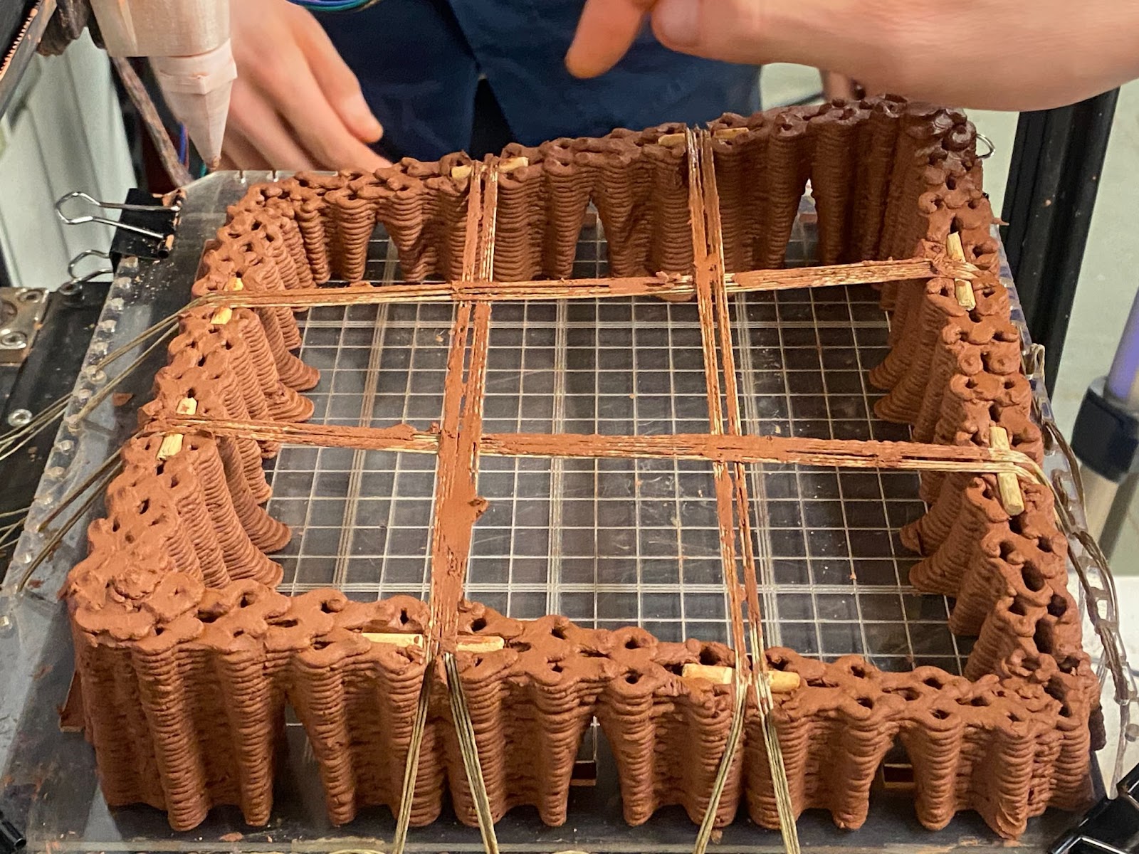
Adapting the vault’s width to its support
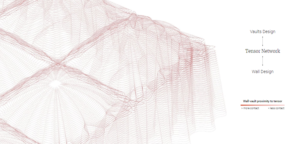
The next step is to add infill to the vault, this will prevent fatal mistakes as it will be multi-layered and also help buckling by increasing the global inertia drastically. To maximize the stability of the vault, it must adapt to its supports. In that case it can be two: the fibers or the walls.
Design lead by network of curves. From network to wall and vault design.
Adapting the orientation of the vault’s ribs to its support.

Model inside picture showing the continuity of the infill.
Infill for a vault creates actual structural ribs. If those latter are matched to the wall that is supporting them, you ensure a strong bond that will prevent more buckling of the vault.
This relationship can be controlled, in that case, support and fibers are placed in a way that creates a specific pattern where desired.
EARTH TO FIBER CONNECTION
In order to be able to position the fibers over walls it was necessary to consider the capacity of the clay to support the fiber depending on the state -wet or dry-. On the other hand, it was necessary to investigate how to anchor the tensor using the ground or eventually the wall.
Wet state of the earth
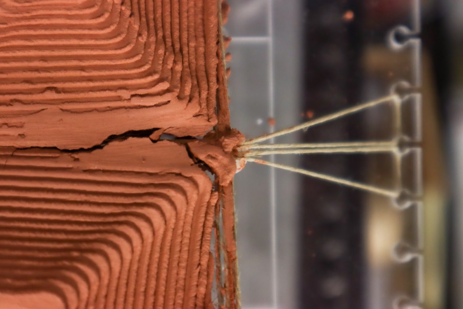
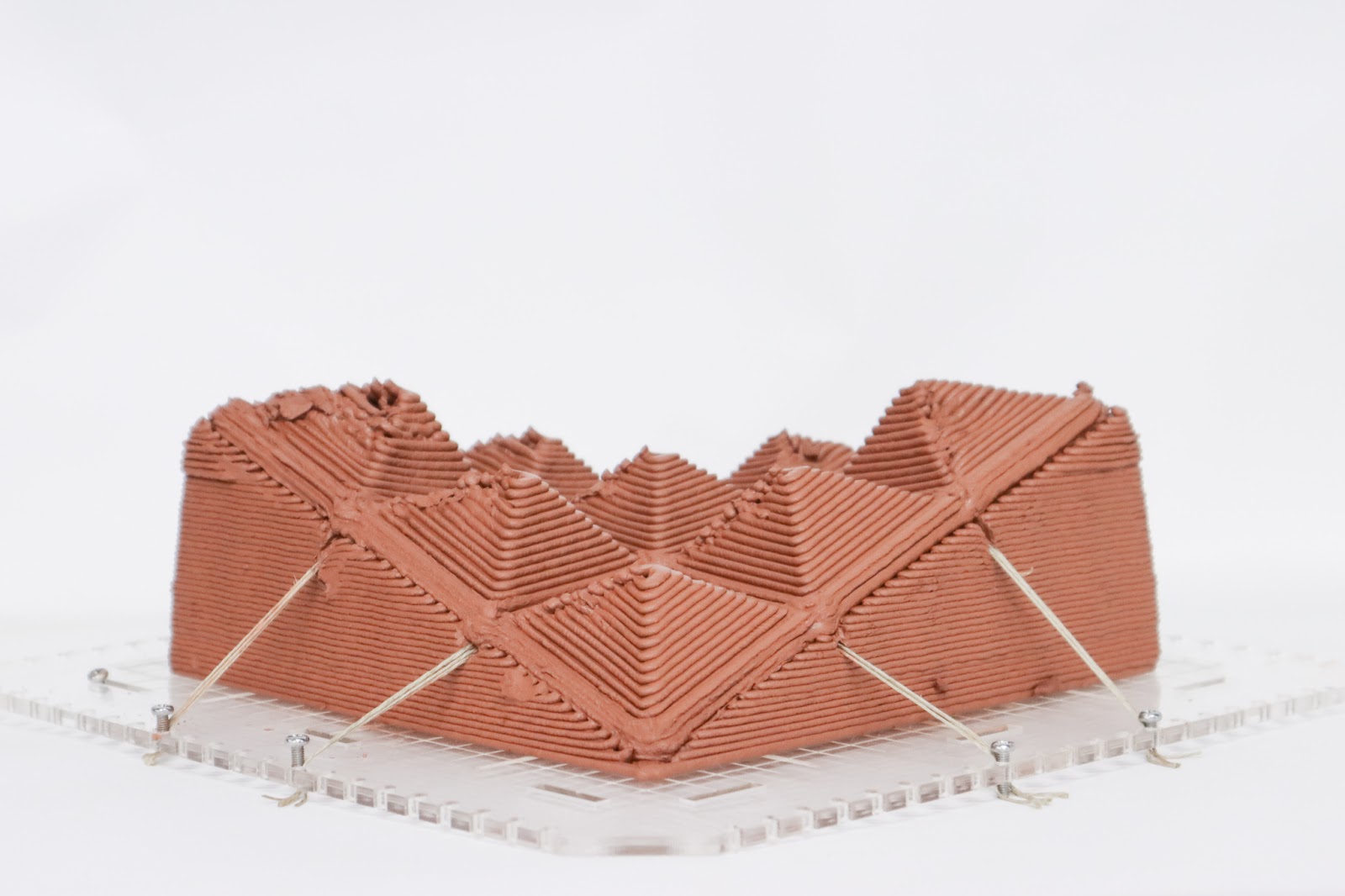
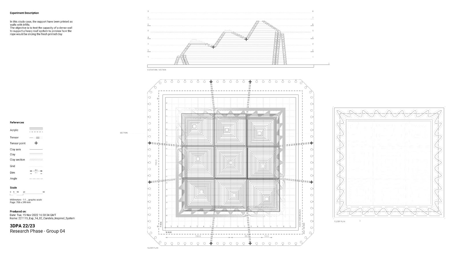
The capacity of absorbing the loads provided by the tensor on the wall will be different depending on the state of the earth. Related to the scale of the print, hours or days after printing the earth will gain compression resistance capacities. But in most cases, a wet state in the walls is needed to ensure proper connection to the top vaults. Also, considering the high loads of the vaults distributed by the minimal surface area of the tensors, they could perform as a wire that cut the print.
During the wet stage, the tensor load applied without load distribution will highly exceed the capacity of the earth to support it.
Research prototype image showing edges of wet stage earth being cutted by tensors
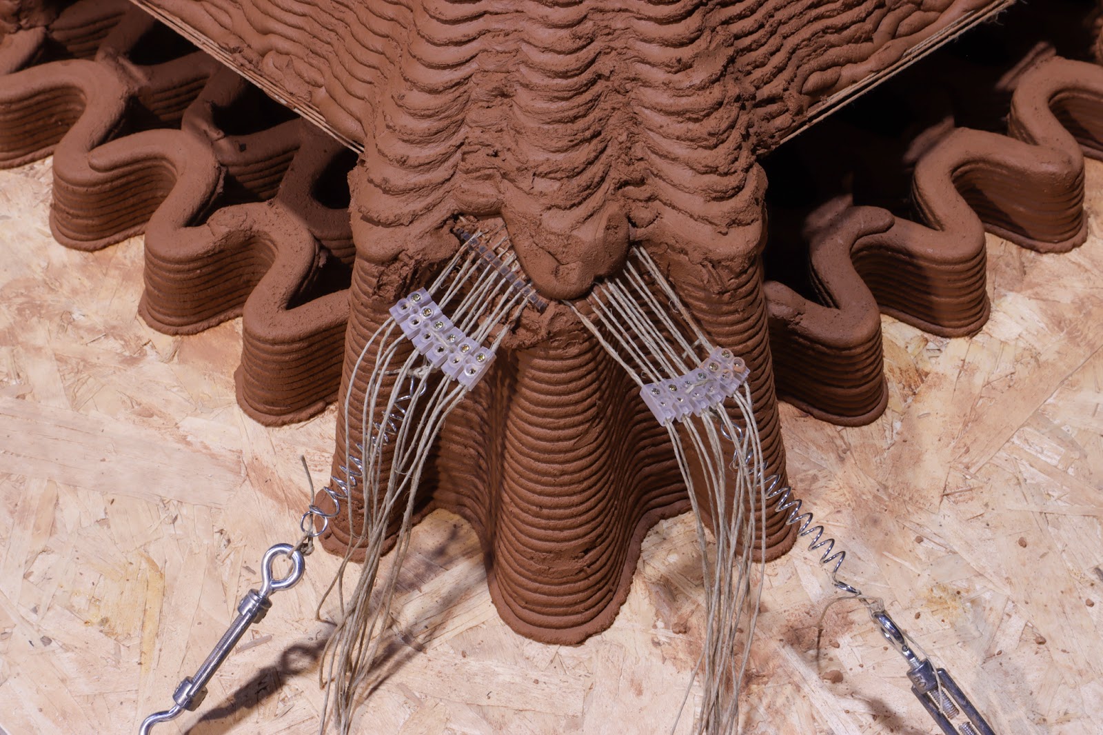
Anchoring tensors and adding intelligence to the walls
A set of systems were designed to eventually allow us to anchor the tensors directly to the wall, avoiding using any external element. Other scales of exploration such as 1.5 prototypes allowed us to explore tensors-to-wall intelligence.
Not only to reduce global shrinkage problems and cracks but also to think of smart pre-assembled processes that could improve mounting time and will make it easy to place all elements into the system “without the need for plans”.
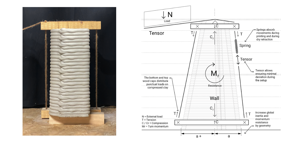
Using walls earth compression resistance to compensate for vaults load on tensors.
Connector prototypes. Designing wall and tensor intelligence at scale 1:5
Scalability
A multi-scalar approach was developed to understand the distribution of loads to the walls with different materials and technologies applied to 1.1 scale, 1.3/1.5 scale, or 1.10 scale, depending on which tools will be available.
Scale 1.1 were found faster and more secure, with pre-designed options that include springs, crickets, or for example heavy-load tensors such as those used on concrete post-tensioning beams or slabs. Nevertheless, loads will multiply exponentially and will need specific tests depending on different fibers and geometries of the wall to understand the real capacity of the system.
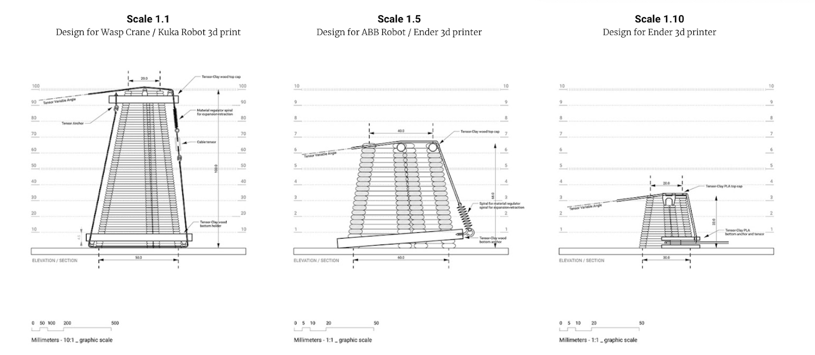
Multiscalar design approach for tensor connector to earth. Tensor position in wall logic trough 1.10, 1.5, and 1.1 scales.
FINAL EXPLORATIONS
In order to test this scalability approach, we prepared two models, the first one follows the 1:10 scale, with the model explained in the above chapters. The second one reaches a 1:3 scale, we used a Kuka robot arm as a tool this time.
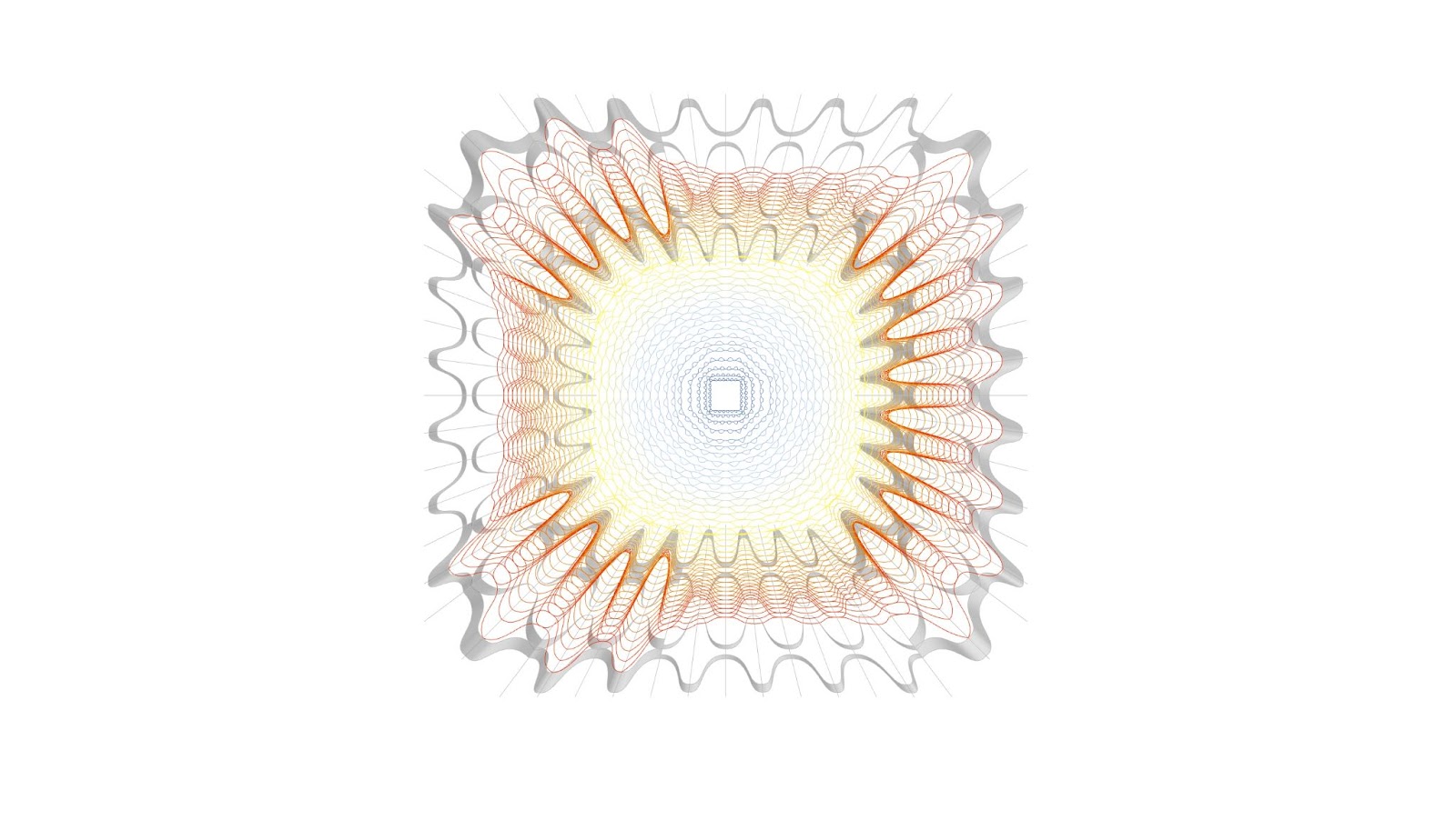
Example of final prototype drawing. The colors represent the vault’s printing order.
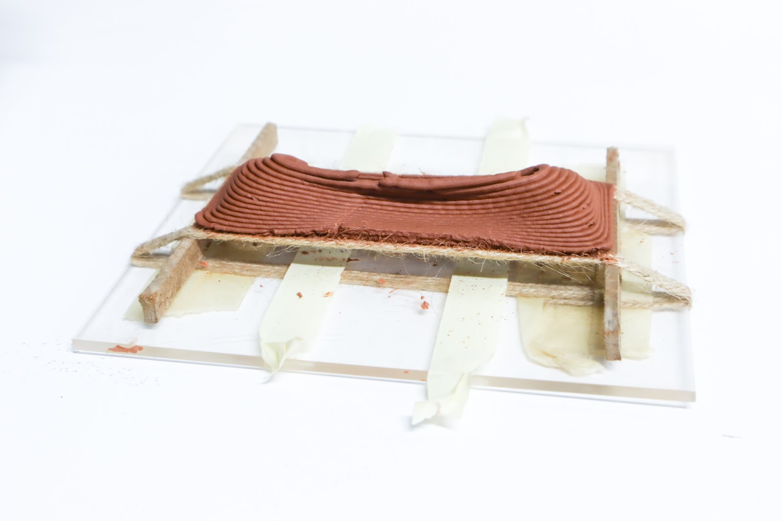
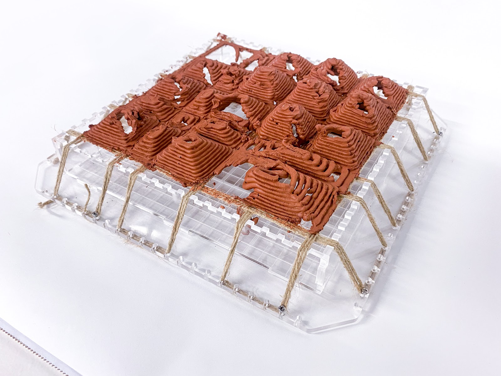
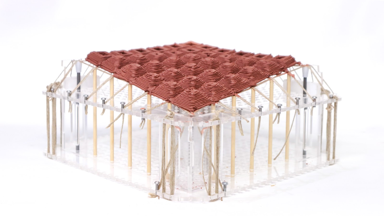
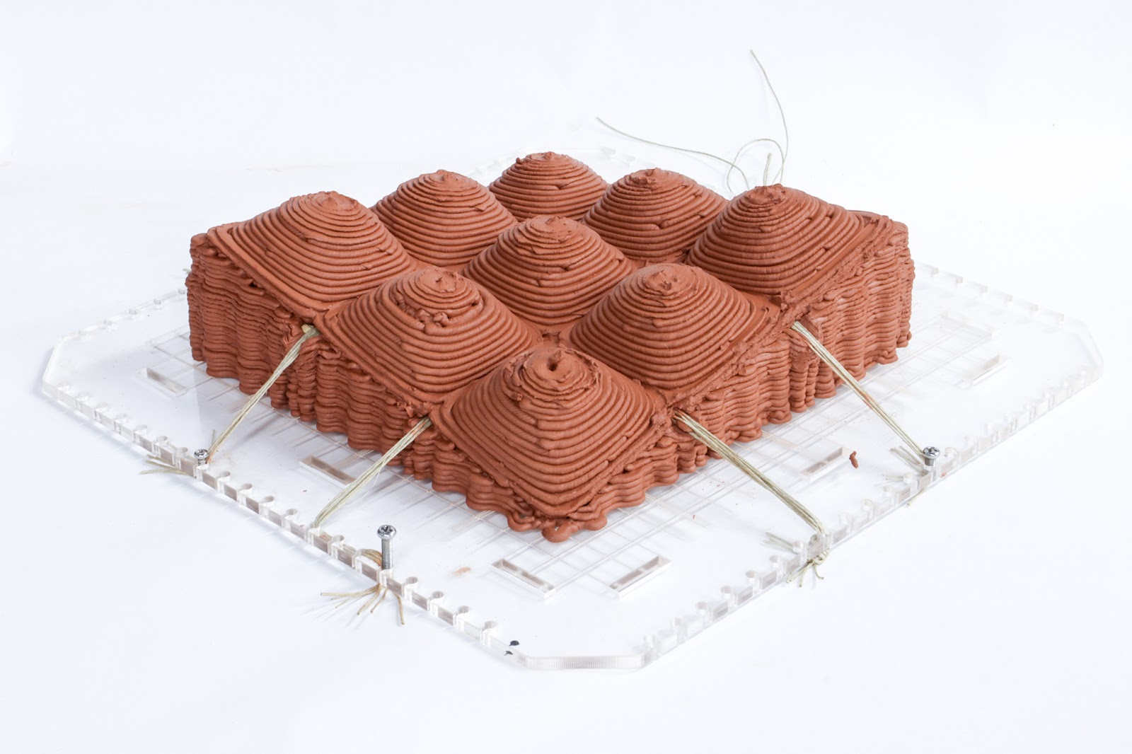
1:10 small-scale prototype
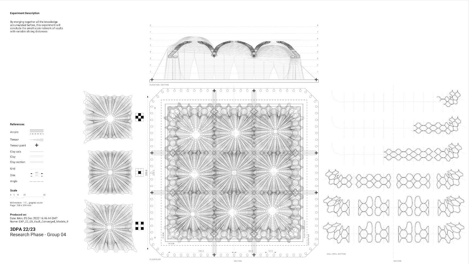
Small final prototype plan and section
Our last small model aimed at recentering the knowledge in order to provide one clean and successful print. As we understood that technical fiber tensioner required a larger scale, we went back to attaching these on the acrylic setup.
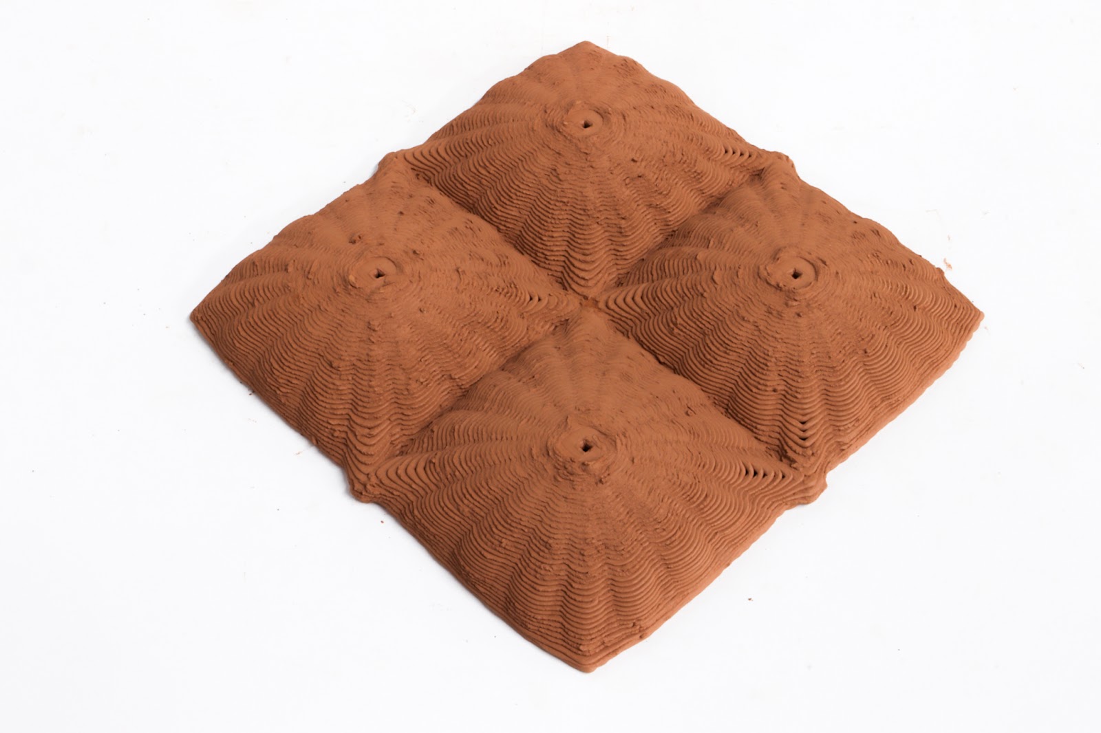
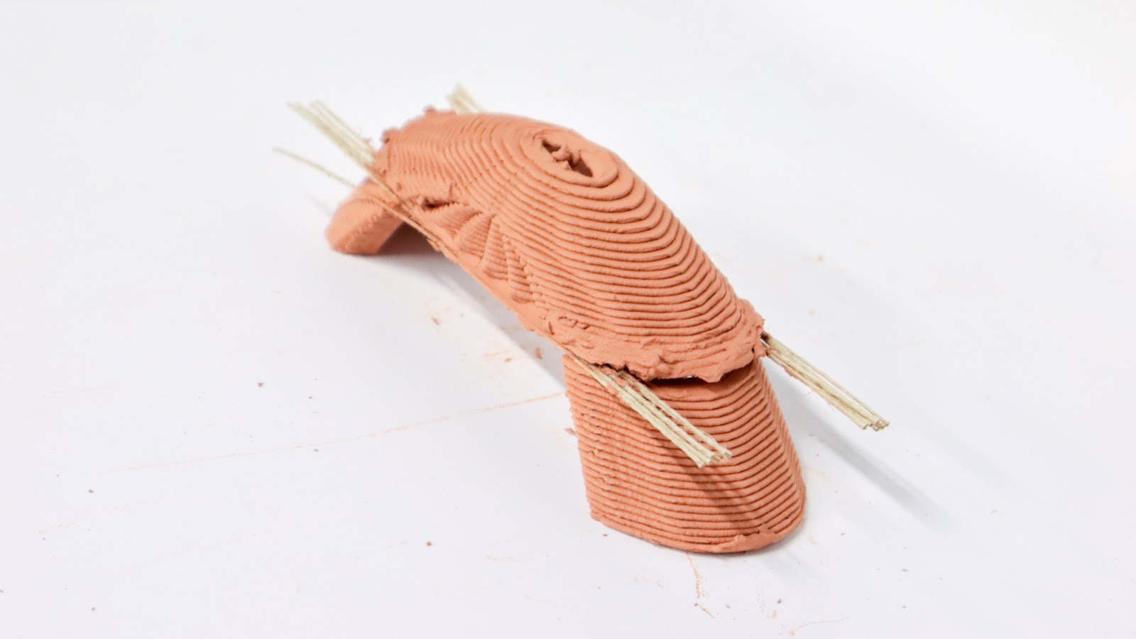
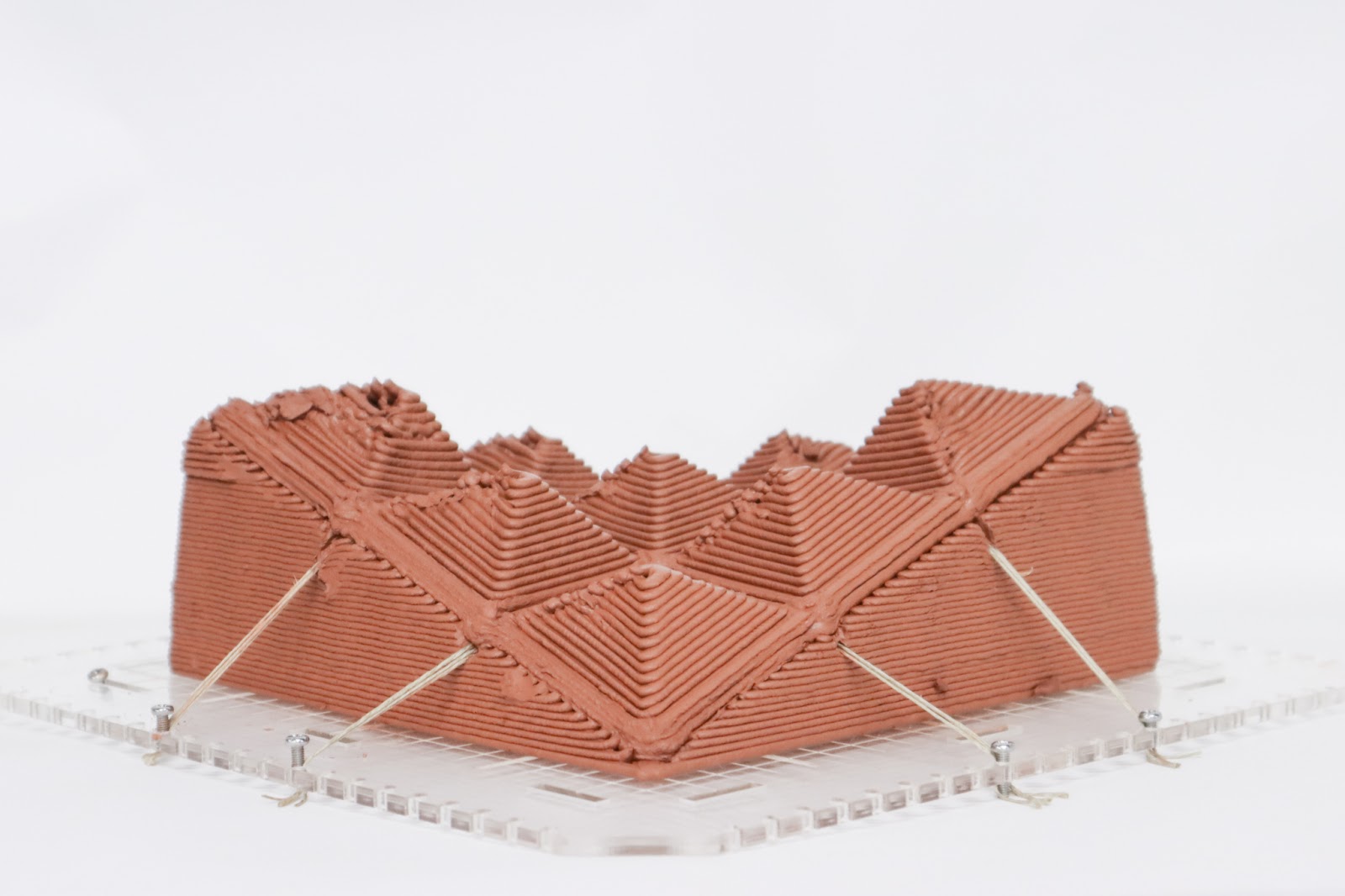
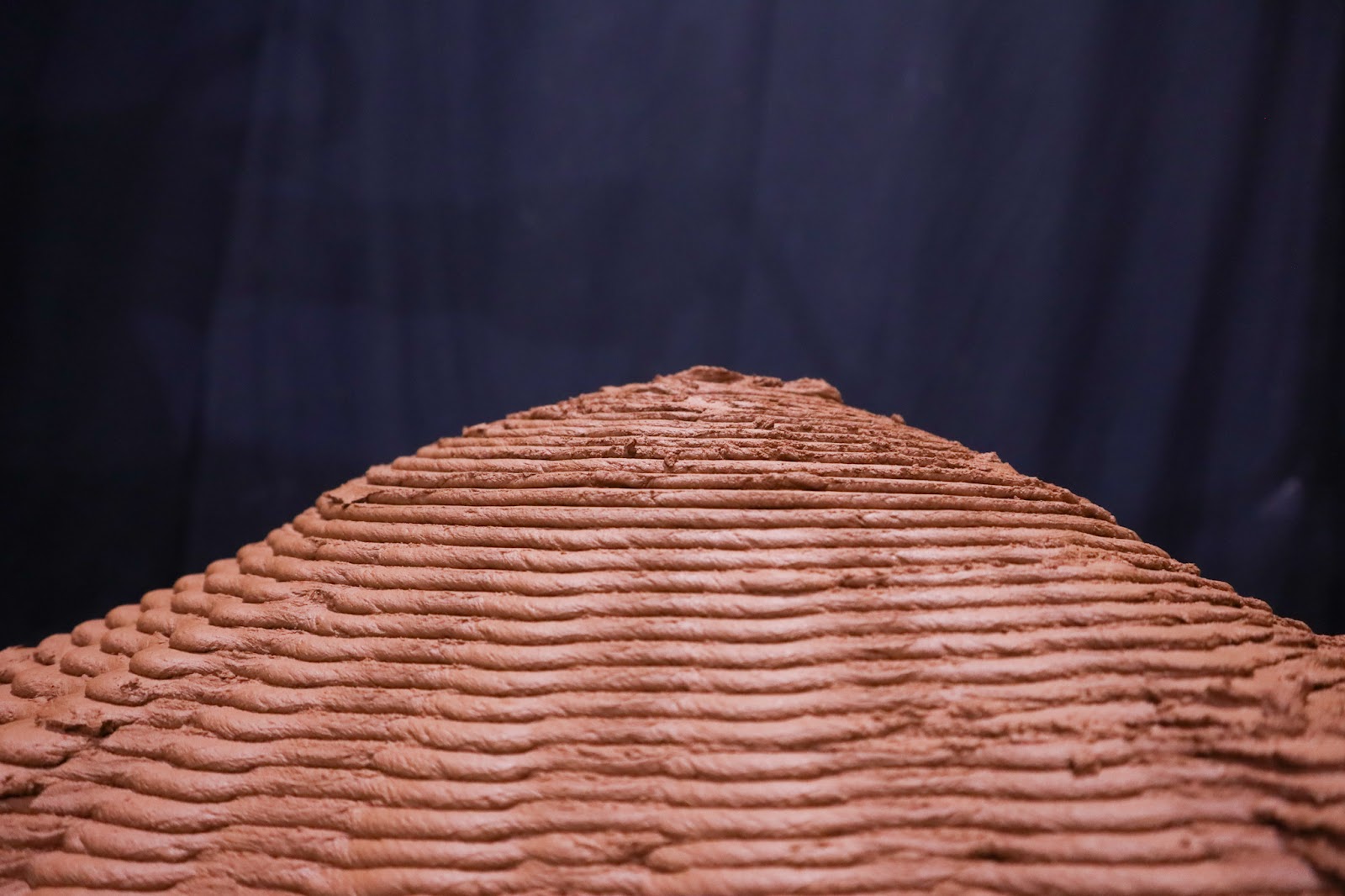
We did everything mentioned above and produced a 200×200 millimeter model that would include nine vaults. Forming an hyperbolic paraboloid.
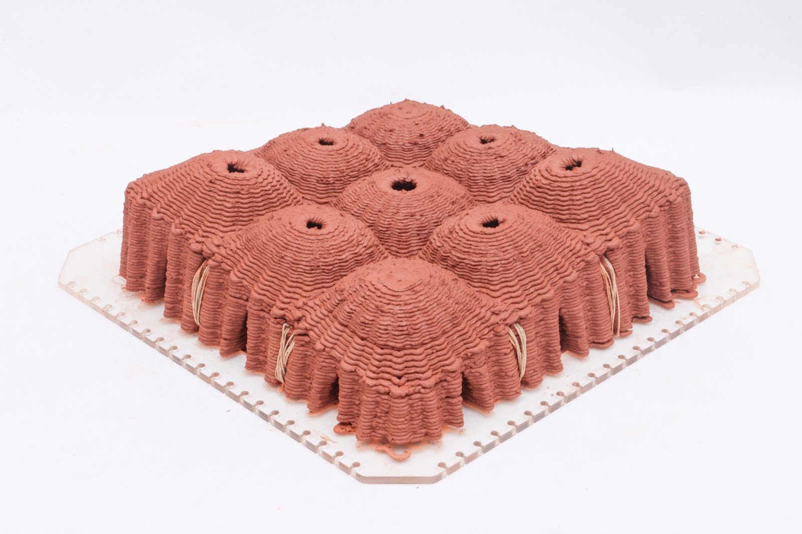
Small final prototype general image.
Fibers were placed precisely, inserted with a wood piece inside to provide more support. They were tensed but not too much, not too slice the clay.
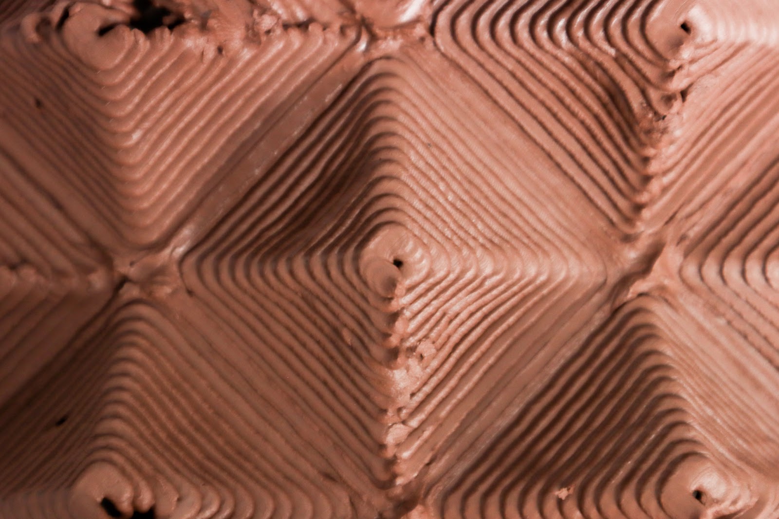
The infill of the wall is matching the infill of the vault and the vault has extra material in the weaker points: corners and over fibers.
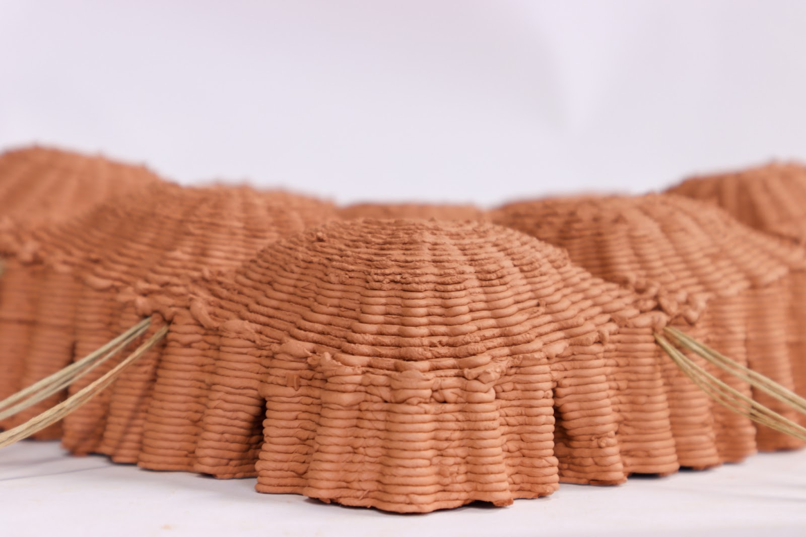
Small final prototype zoom image of wall and vault connection.
We decided to leave some openings to the vaults as a variable oculus. Some shapes would have light and others would be close. We are saying here that we can close but it doesn’t have to be. It can, architecturally speaking, be an interesting element, especially if under control.
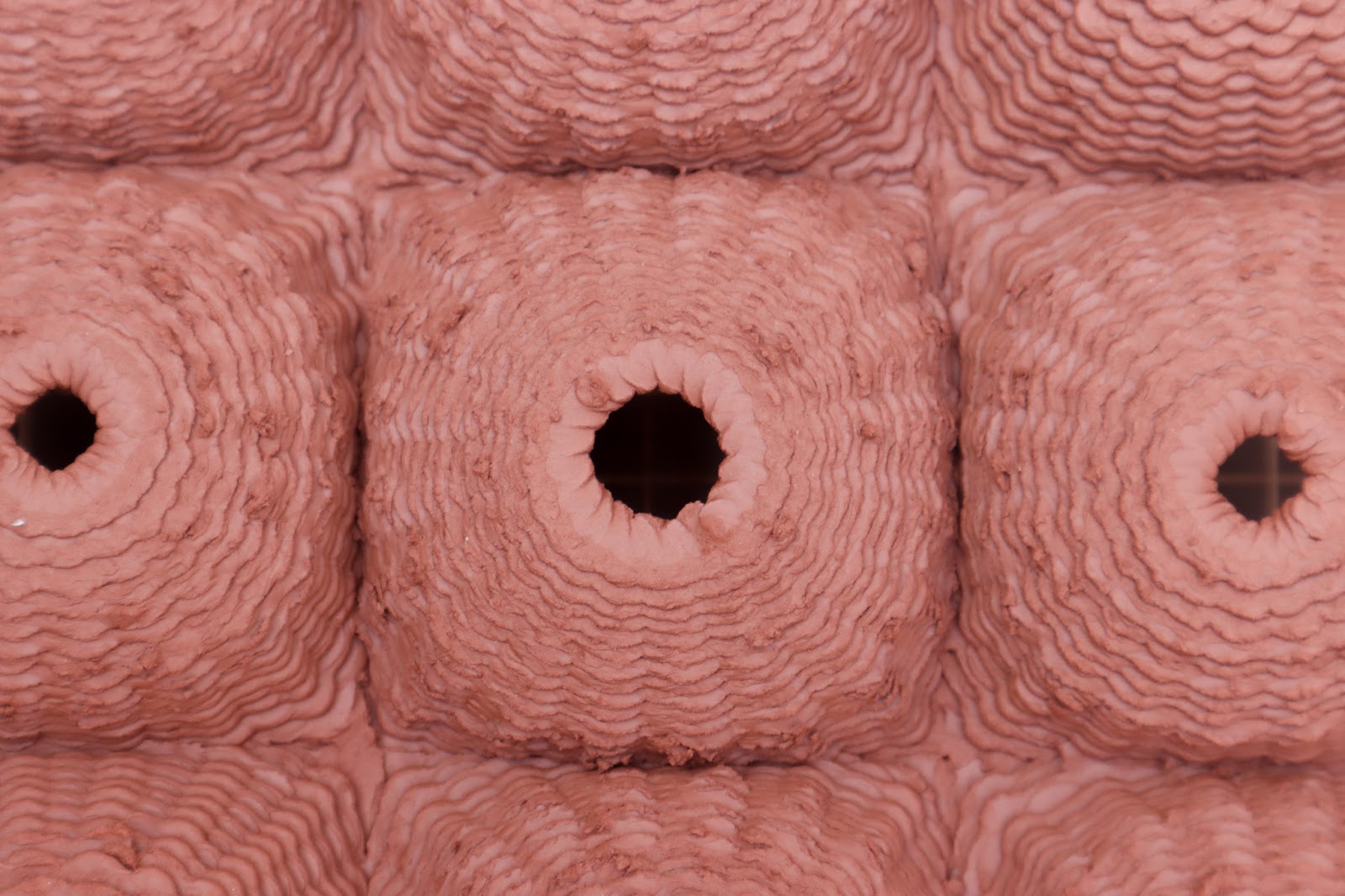
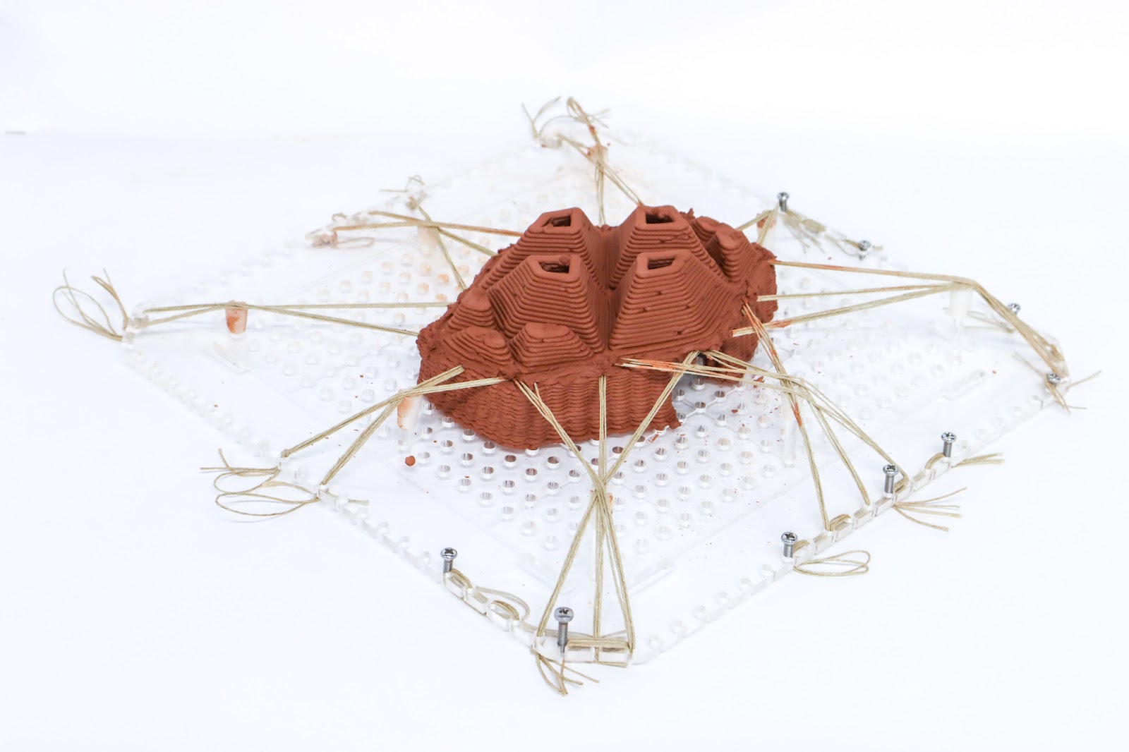
Small final prototype zoom image showing vault slicing and openings.
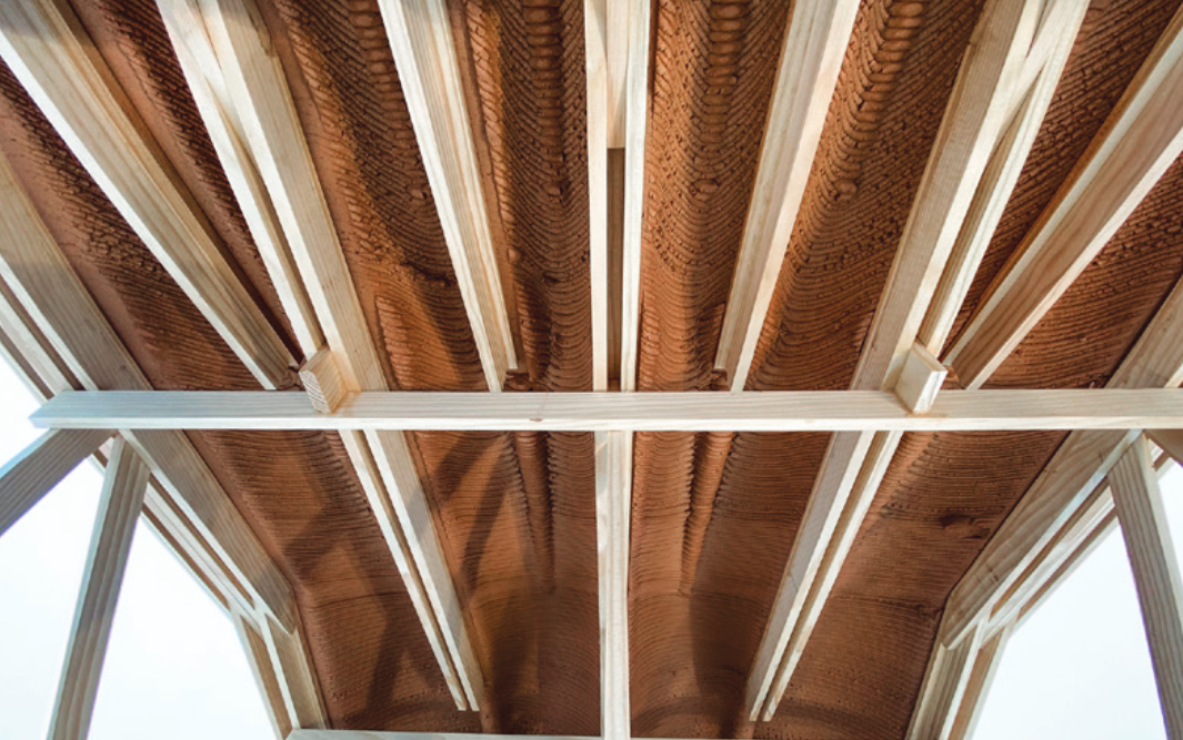
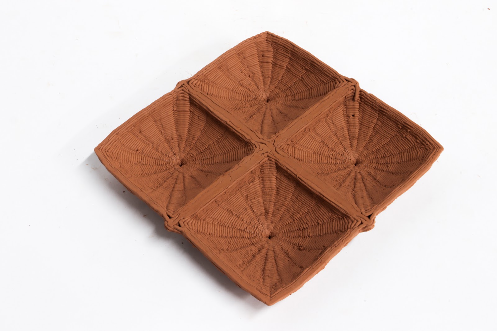
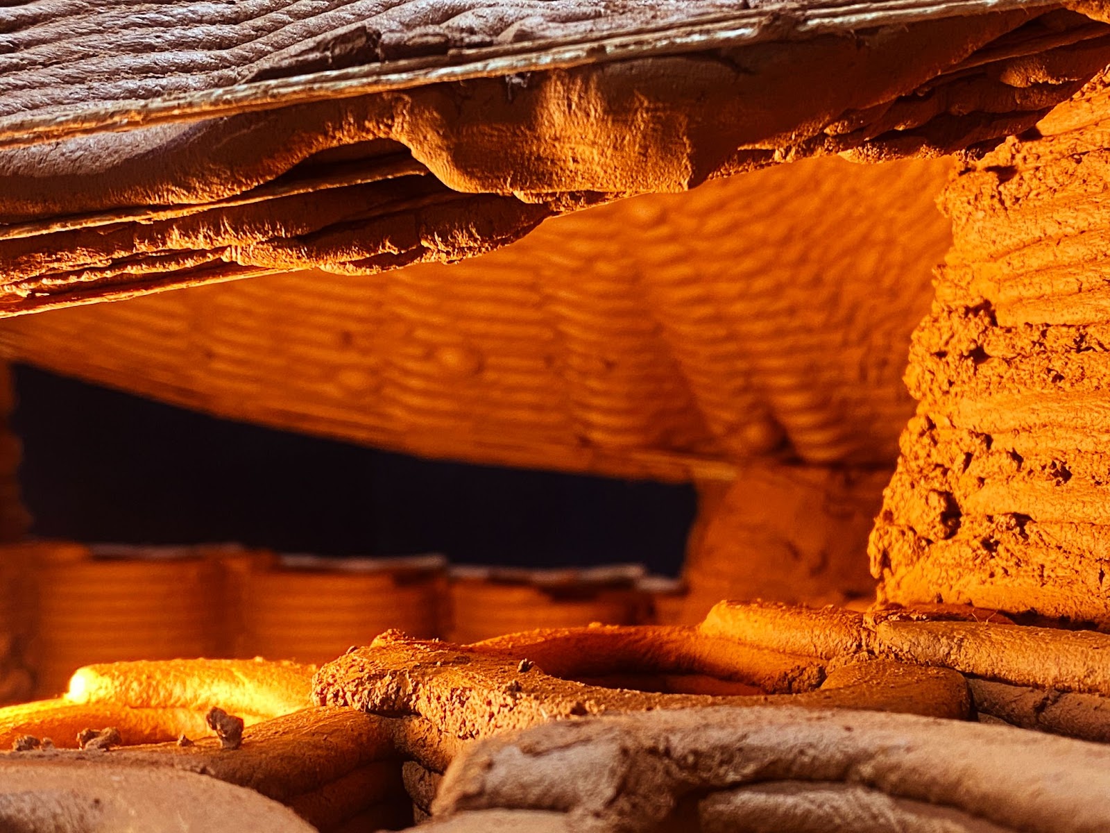
For underneath, we can also see that the infill is creating an interesting rib system that shows the complexity of the model as well as the architectural power that it could provide.
Small final prototype image showing system from bottom part.
Drying, the model proved to be, this time, resistant enough to resist the 10% shrinkage of the industrial clay that we use for such models, as no cracks could be noticed.
In order to reduce printing time, openings were inserted, as “doors”. Also, even if not used, the openings for the tensor to clay connection were inserted, to provide a model as it would be, if made bigger. It helps us understand what it could look like.

Small final prototype detail image showing connections and wall intelligence.
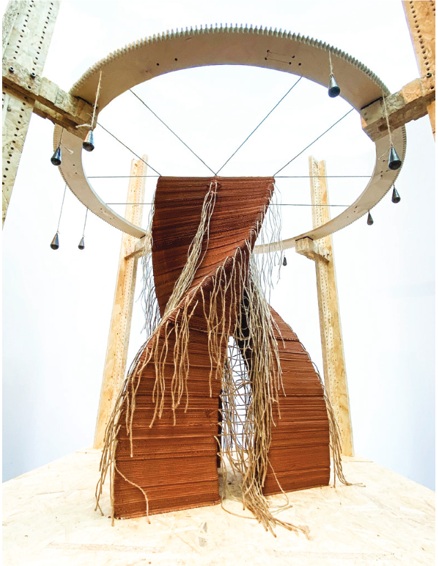
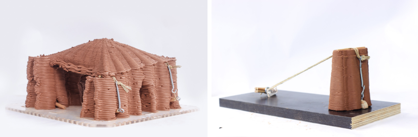
1:3 medium-scale prototype
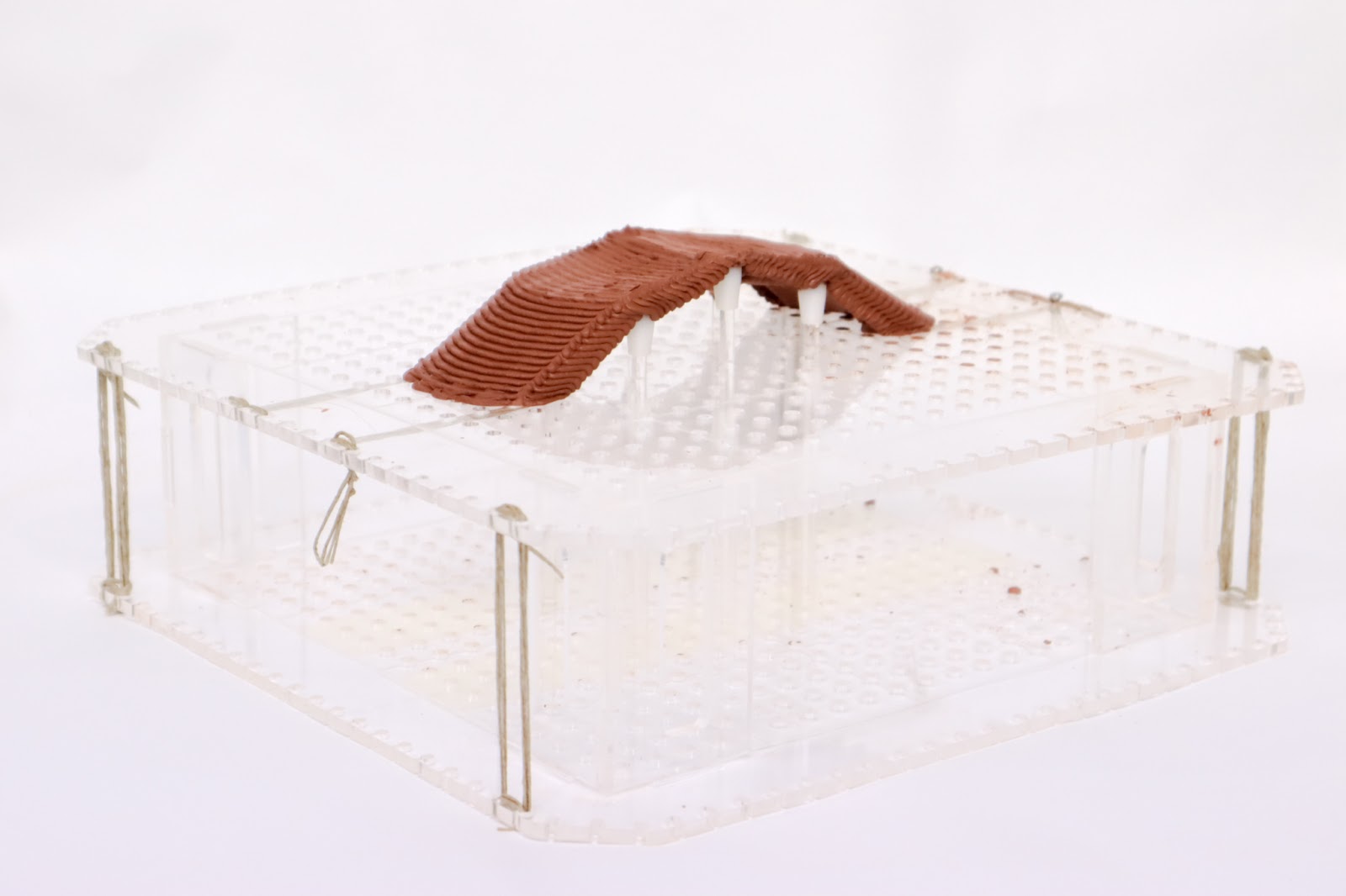
Changing scale allows us to experiment more on connections. However, as a first trial of this size, we decided to keep things simple by printing a single vault that would rely on one wall and two columns, using three tensors we can obtain a square base on which we are able to print the vault.
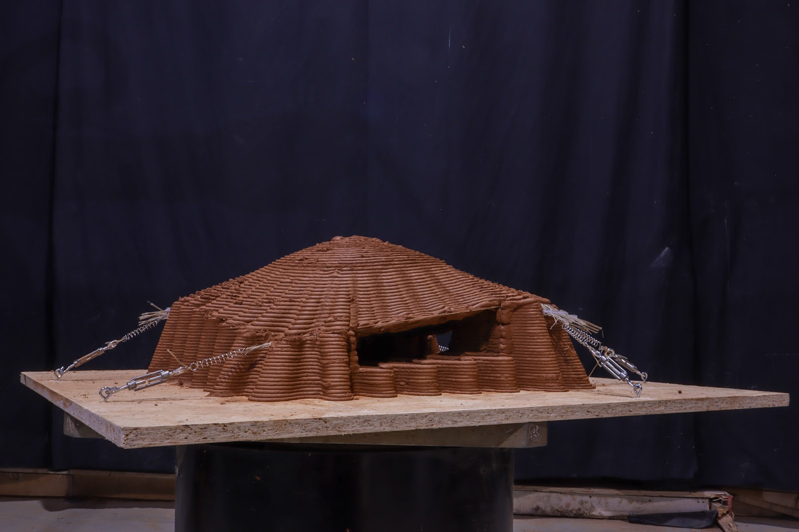
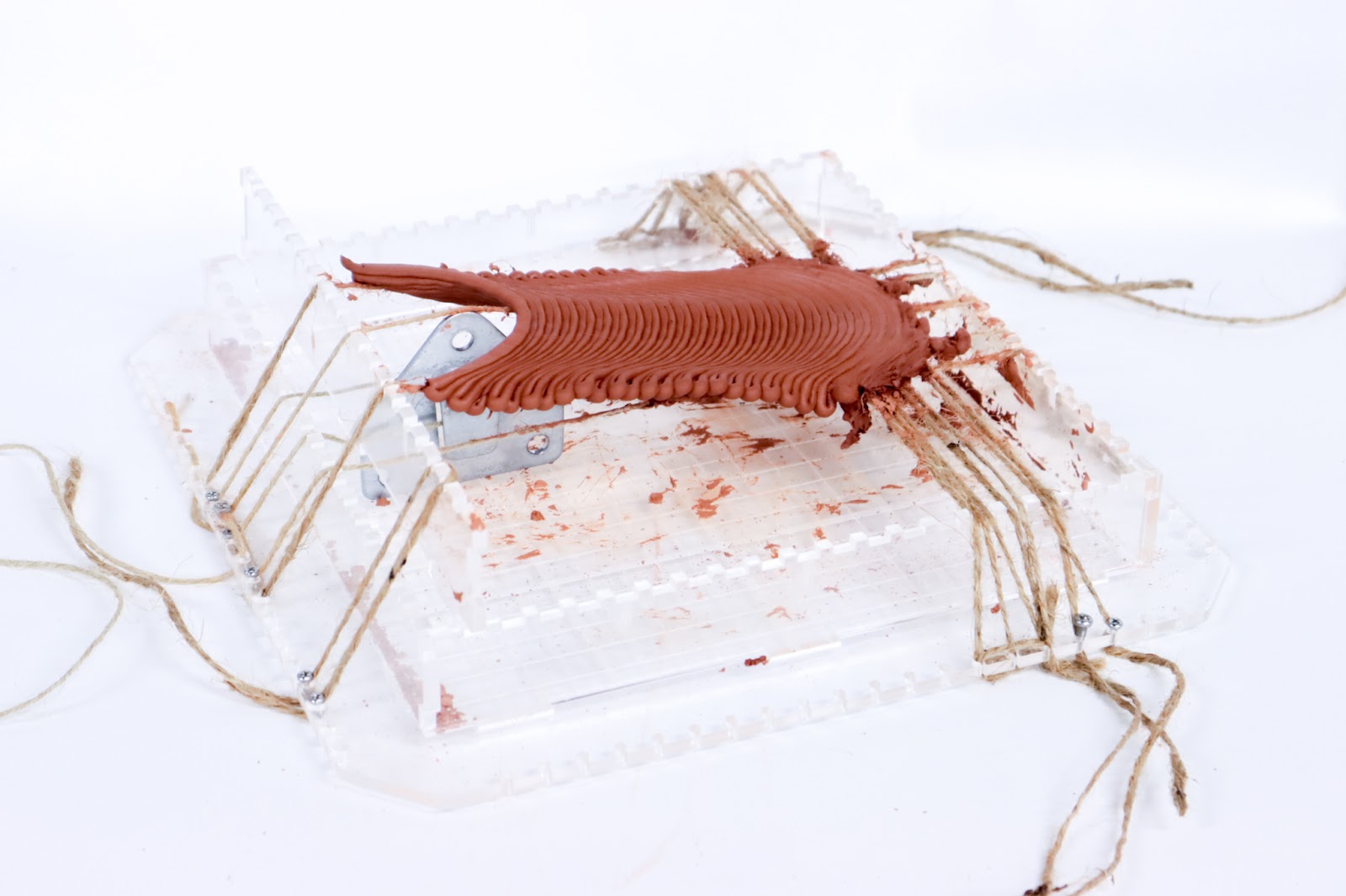
Medium-scale final prototype general image.
We knew we were going to face some retraction challenges as the vaults over the rope would not connect. It is usually better for the clay to stand on the fibers and have a center of gravity that stands over it. In that case the weight, coming only from one side of the rope will make the fiber tensor rotate on the side of the vault.
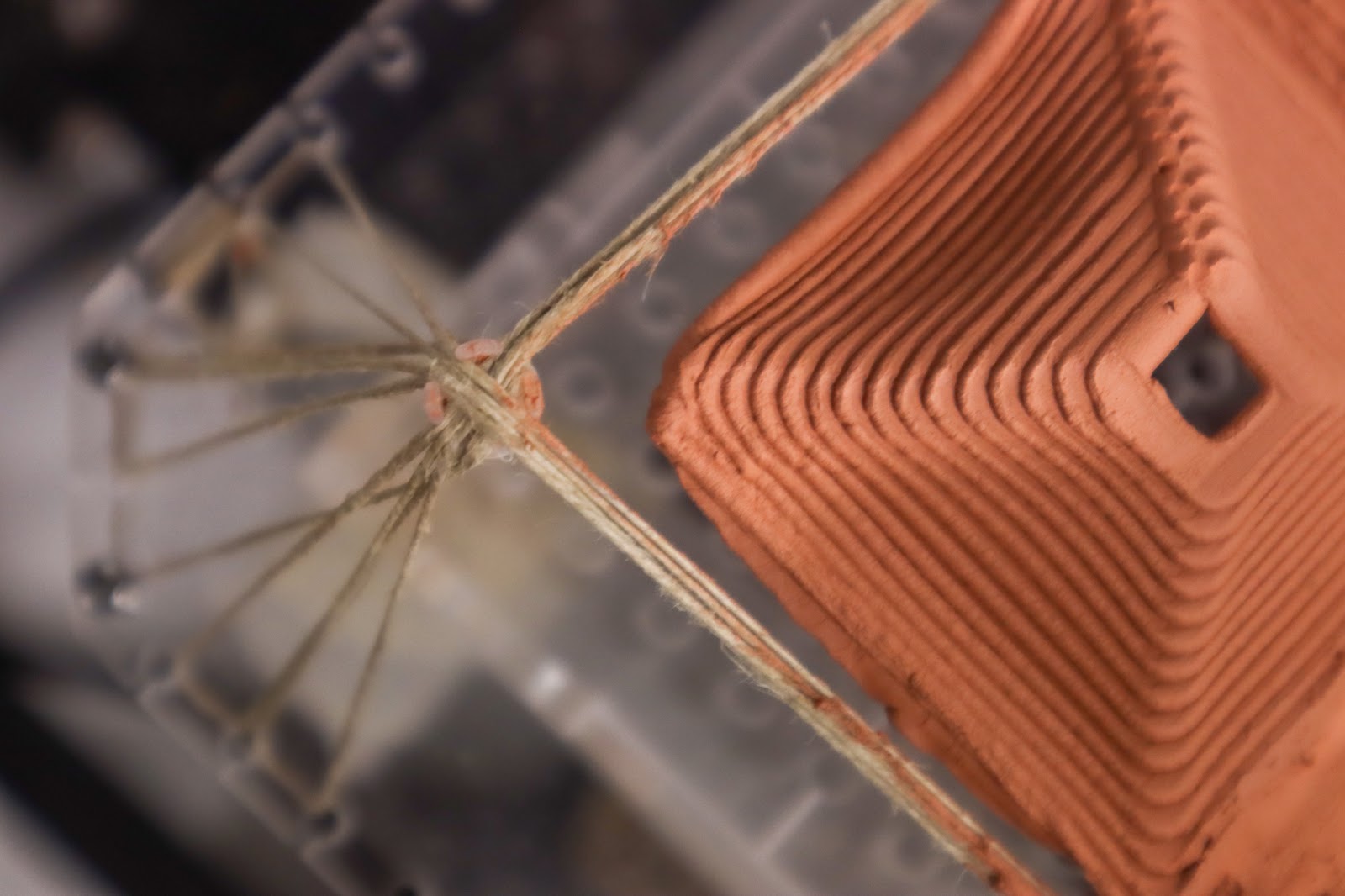
Medium-scale final prototype detail of tensor connector.
Also, the robotic arm being a very dangerous tool, we could not stay around it and fix the rope’s position if not placed precisely enough. We put a lot of effort into good preparation, precise digital models that allow good planning. Tensors were made in advance, knowing the right needed length. So the setup was fast and smooth. It was actually easier to put things together as they were bigger. With actual industry standardized tensor mechanism, we were able to tense the rope evenly and with the needed strength.
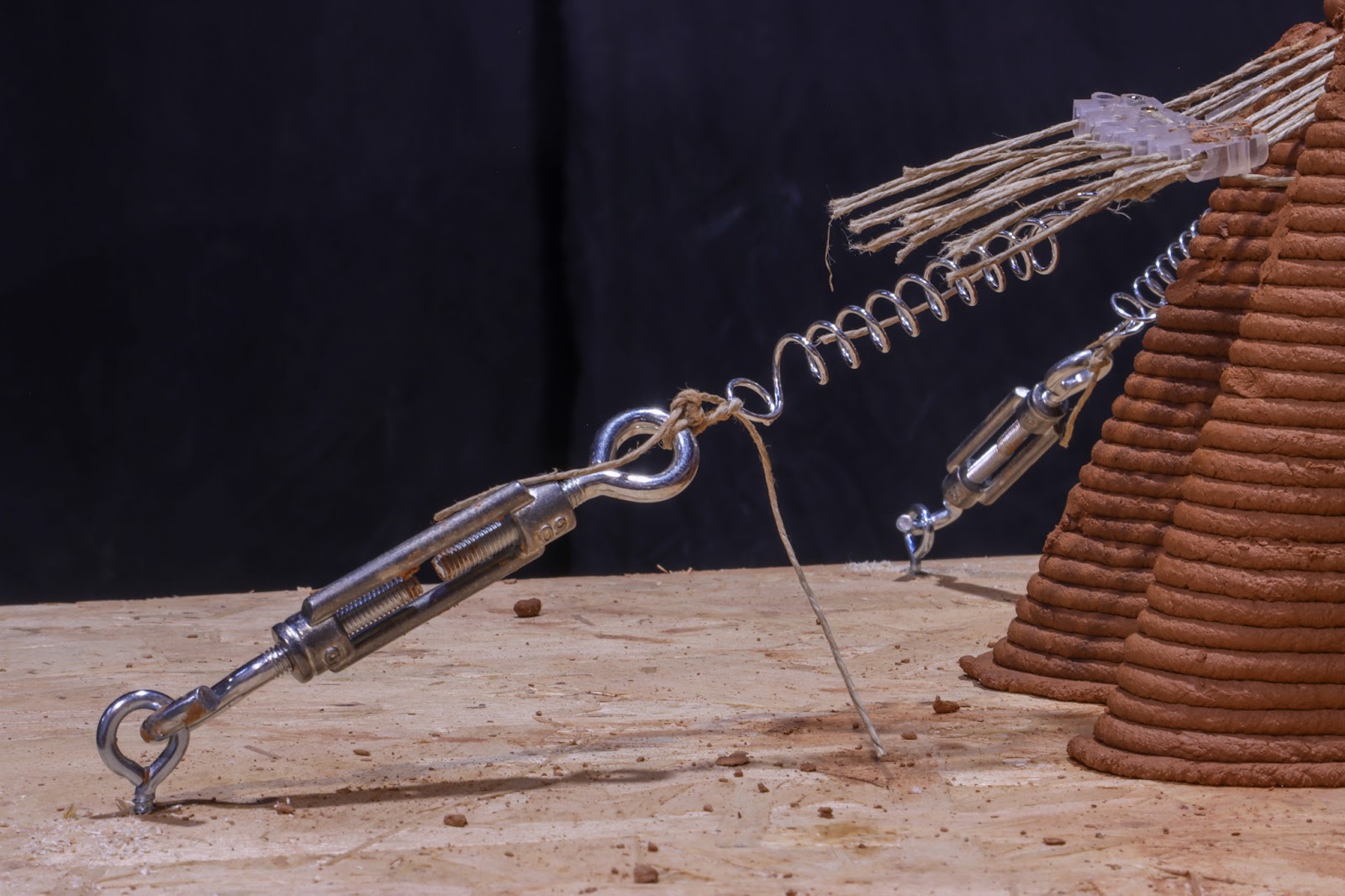
Medium-scale final prototype detail of tensor connector.
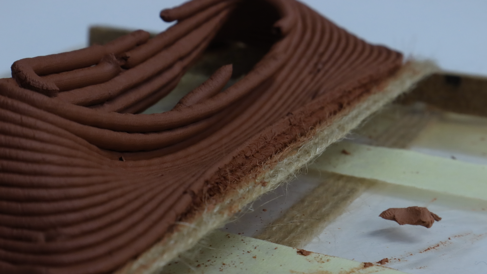
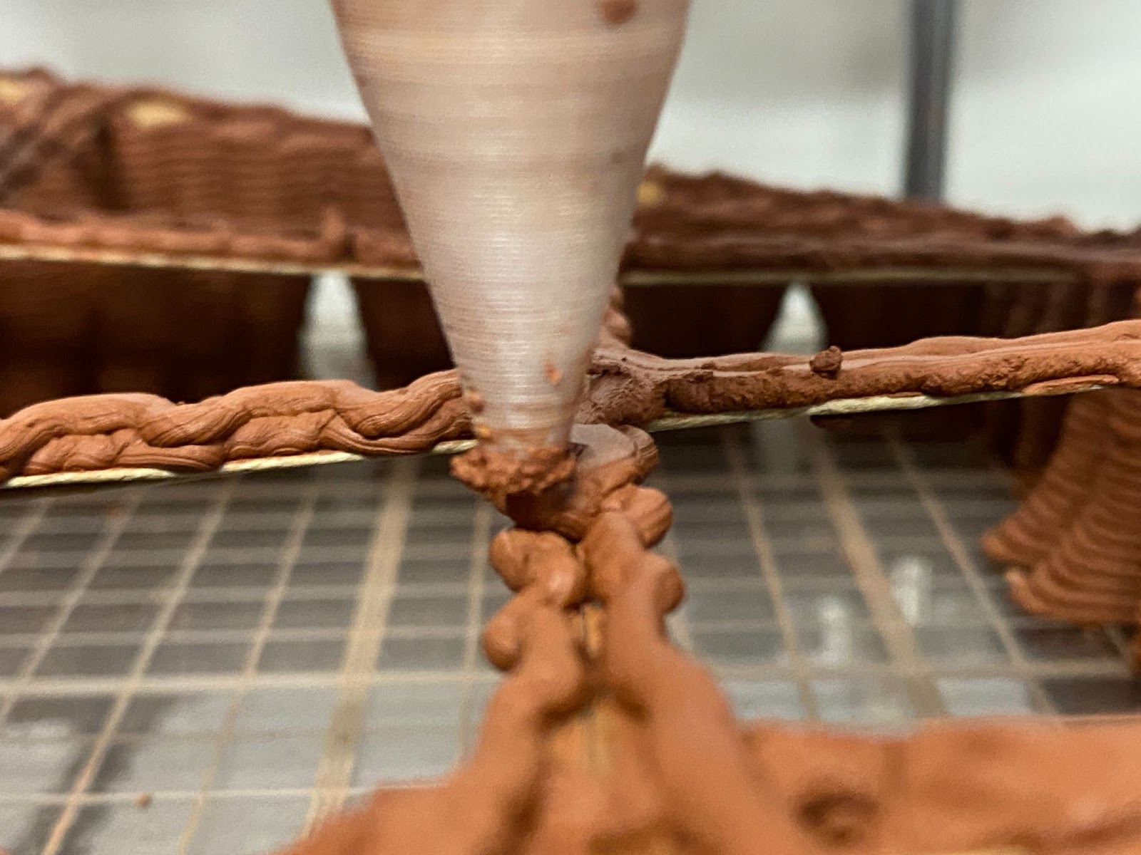
To be sure of the placement of the latter, we runned a first dry layer of the vault. Using this we were able to correct their placement without pouring material.
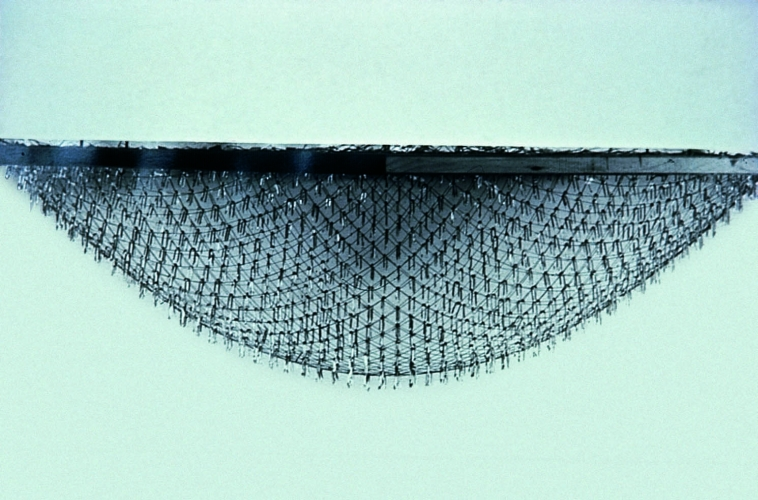
Close-up of the junction between the fibers and the clay. The fibers grab the clay like a fishing net..
After this, the first layer was printed as a separate code, to be sure to be able to run it again if something was wrong. As it seemed fine, we didn’t run it again.
Afterwards, we launched the entire vault process and it went smoothly. We noticed some buckling on the sides where the vault was resting on the fiber but that was expected.
Medium-scale final prototype detail of vault variable slicing.
During the drying process one of the corners cracked, because of the retraction and the amount of fiber that was inserted in a specific point. From what we have seen, the lower corners of the paraboloid are weaker because there is less material if the wall is lower. However one of these two low corners was resting on a wall, the other one on a column. The latter end up having some cracks.

Medium-scale final prototype, once dried, presented one crack.
FURTHER DEVELOPMENTS & TOOLKIT
In order to sustain further research on the topic, we created a toolkit consisting mainly of a detailed grasshopper script. The script explains how to take care of every part of the shape’s design, with two scale approaches: 1:10 and 1:3.On the other hand, it is possible to find here and understand all the constraints related to the success of a print that uses fibers as support.
In the first part of the research, we opened several leads that could become further research. It could be interesting to explore different fiber networks, networks with integrated poles, using the network of fiber as temporary support instead of full support (Printing only over the corners, for example). Printing over rope and fabric hybrid, etc. It would also be interesting to start testing fiber networks on the same scale, but a full network instead of a single cell, now that that one proved to be possible.
Also, exploring the bigger scale, considering the problem of tension, would need further testing and experimentation. It would also be interesting to explore this concept applied to specific reinforcement, like staircases, and integrated furniture, where the overhang required is small and we need something that performs better with shrinkage than a wood plank.
Toolkit is available online on github.com/fmruy/3dpa_research_tension_networks
CONCLUSION
Based on the results obtained, the research demonstrates a promising construction method that shows interest in further development. In particular, by increasing the scale of the experiments, a whole new set of challenges could be achieved by developing more refined designs.
We tried, as far as possible and about the material and temporal constraints that we had, to get as close as possible to the 1.1 scales to understand as well as possible how these fiber networks interact with 3d printing. However, the experiments we conducted at a low scale gave surprising and encouraging results, proving that these systems could work and can partially provide answers to the question of 3d printed roof systems.
Compared to centering and formworks -traditionally used in the construction of vaults and shell structures- this strategy required little extensive costs, in terms of time and material.
In addition to the economic aspect, fiber networks would allow flexibility in support placement. They would not require complex fabrication processes and design to be integrated into the print design as part of the wall’s design. Tensors can be produced with wide market available inexpensive components. Networks can be tri-dimensional or two-dimensional, generated from a lot of various shapes as they can be discretized into a line. Therefore, lines can follow planes, ruled surfaces, or even cross other surfaces in predictable manners.
However, using tensor networks and fibers requires a cautious approach considering the setup. They need to be tensed properly and placed precisely. As was confirmed in several prototypes, tensor moves, rotates, and bends. They will not be as predictable as a digital fabrication machine. A basic robot setup without spatial recognition will follow an initial design without taking into account the movements or displacements in the geometry. Even if our research has been largely focused on covering spaces, this method could be used for other architectural purposes such as smaller and lighter details like windows, doors, and stairs.
In addition to being extremely flexible, this approach fits in an ecological and economical context of resource wastage, and coupled with the 3d printing of raw earth taken on site, it could allow a drastic reduction of costs and material, without devaluing the quality of the architectural proposal, aesthetically and structurally. With further explorations, fibers could collaborate to push the limits of additive manufacturing, a technology that already contains in itself a fertile ground for architectural innovation.
BIBLIOGRAPHY
- The Trulli of Alberobello, n.d. . Unesco Beni Culturali. URL
- https://www.unesco.beniculturali.it/en/projects/i-trulli-di-alberobello/ (accessed 10.20.22).
- Ibid.
- Frei Otto [WWW Document], n.d. URL http://www.freiotto.com/Boegen.html# (accessed 12.14.22).
- Ibid.
- Reforming and Performing: Thin Shells in Practice and Education, n.d. URL http://thinkmakebreak.blogspot.com/2014/03/reforming-and-performing-thin-shells-in.html (accessed 12.14.22).
- Bryson, Z., Coutinho, B.G., Polvi, F., 2020. Embedded supports for 3D printed earthen architecture
- Brenda Freitas, Nitha Shivapuram, 2021. 3D Printing vaults and domes.
- IAAC OTF, 2020. Final Booklet.
- Ibid
- STRUCTURE magazine | Think Formwork – Reduce Costs, n.d. URL https://www.structuremag.org/?p=6141 (accessed 12.4.22).
- Rolex Learning Center | SANAA / Kazuyo Sejima + Ryue Nishizawa, Design-to-Production, Rolex Learning Center [WWW Document], n.d. . Archello. URL https://archello.com/es/project/rolex-learning-center-2 (accessed 12.14.22).
- Veenendaal, D., Block, P., 2014. Design process for prototype concrete shells using a hybrid cable-net and fabric formwork. Engineering Structures 75, 39–50. https://doi.org/10.1016/j.engstruct.2014.05.036
- Swiss Pavilion by Peter Zumthor – Roland Halbe, n.d. URL https://rolandhalbe.eu/portfolio/swiss-pavilion-by-zumthor/ (accessed 12.14.22).
- Ruled surface, 2022. . Wikipedia.
