Introduction
In our studio project, we use a combined bottom up and top down approach to develop a mixed use building; designed to integrate multiple functions, including residential, recreational, and commercial, within a single structure. Our goal is to feature a flexible layout, using modular construction techniques and clear circulation patterns, with well-designed junctions. Programmatic variations feature the different functions within the building, contributing to both aesthetic diversity and practical use.
One of our key concepts is circularity. A circular building is designed with modular components that can be assembled and disassembled, allowing for easy upgrades and functional changes through the life of the building. Our design process optimizes multiple objectives, and allows users to explore various design options based on input parameters ranging from urban to component. This approach enables design to emerge organically from the relationships and interactions between these parameters; where individual components contribute to a cohesive system. Housing modules are adaptable, enabling functions to shift between spaces and ensuring long-term flexibility.

Although this mixed use building encompasses four primary functions, our exploration primarily focuses on the relationship between social spaces and housing units. Social and living units are divided into customizable sub-components to allow variety, enhance the human scale, and foster a vibrant sense of community throughout the building.
Workflow
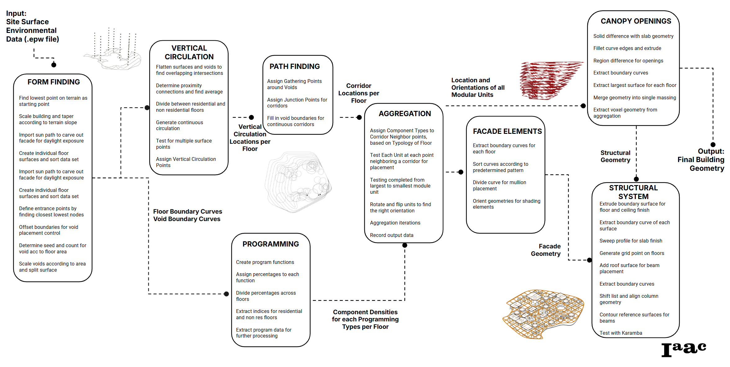
Form Finding Overview
Our building follows a node based form finding approach, inputs contextual site information and uses attractor points to carve a form from a building mass.
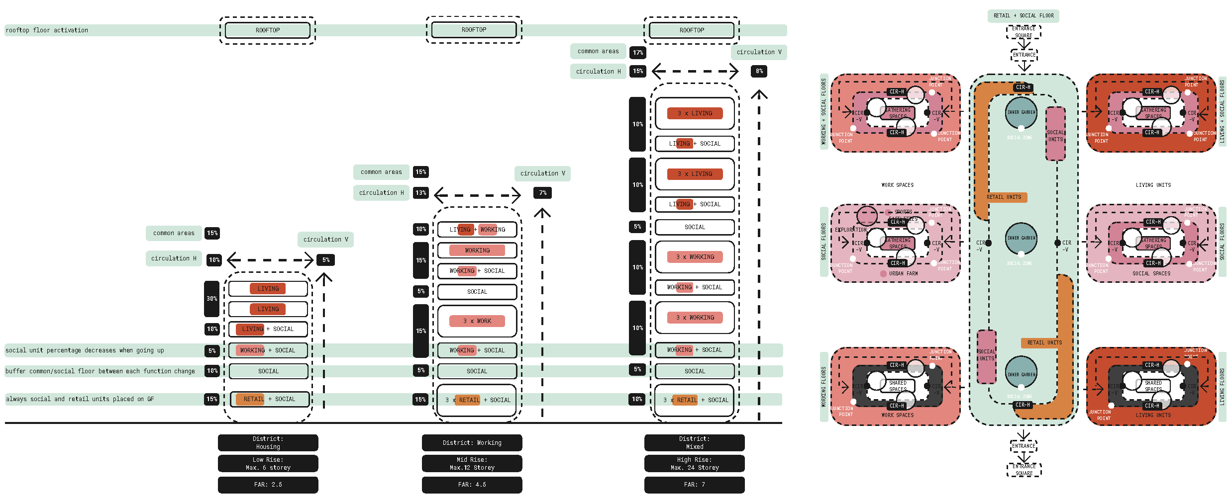
Program distribution begins by allocating each function level by level, guided by the primary functions derived from the surrounding context. After determining ratios for each function, the ground floor is shaped by strategically placing entrances in alignment with main pedestrian access points and nearby attractions.
Inner gardens or atriums are then carved from the site mass, to meet natural lighting requirements.
Next, floor-by-floor distribution is organized around these voids, with circulation and gathering zones radiating outward to create a cohesive and functional layout.
Floor shapes are defined from the site boundary footprint and then projected to the height specified. They are scaled according to the site terrain to ensure a taper that matches the topography, after which we apply other form constraints such as sun vectors.
Converting the initial floor curves to closed planar curves became a challenge for further processing as each curve goes through a different modification during the form finding process.
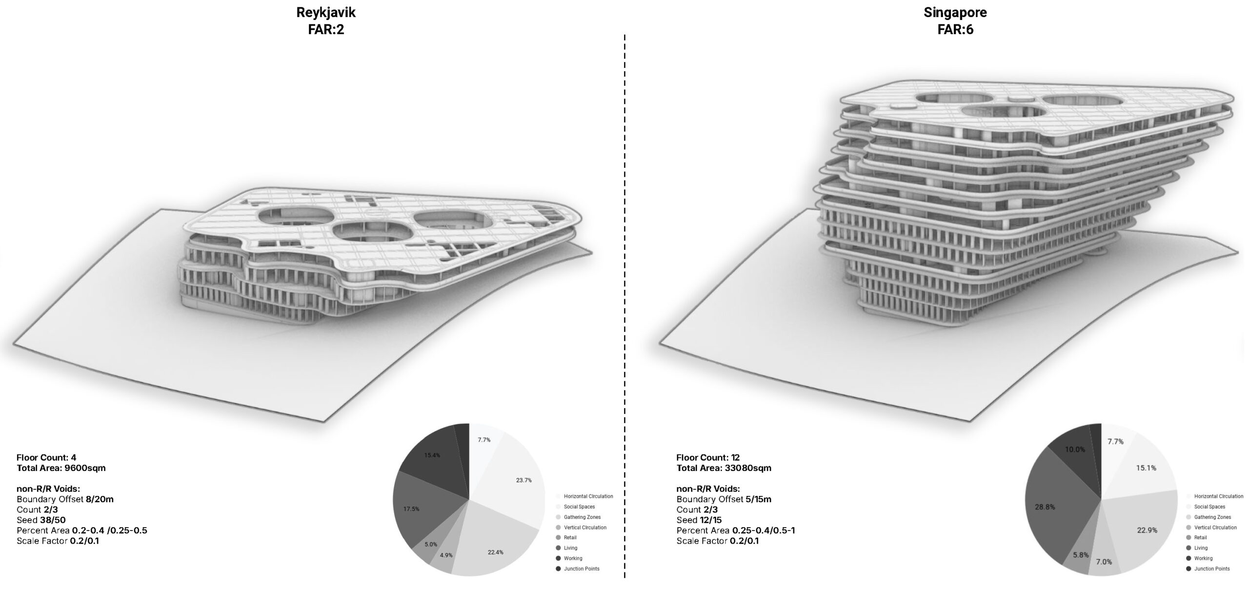
The voids are generated according to each floor’s programming and the percentage of void on each floor is determined by the total floor area. Our algorithm separates each set of floors according to the programming for more refined control over its form. Residential floors require a greater void area than others to more densly aggregate our residential modular units.
The building is further modified through our sun vector “mine” concept. We apply sun vectors to our building form to carve out solar collection areas, and influence the void placement on each individual floor.

The form-finding process begins with identifying the lowest point on the terrain as the starting point for the building’s placement. The building is then scaled and tapered based on the terrain’s slope to ensure alignment with the natural topography.
To optimize daylight exposure, the sun path is imported to carve out façade elements, and individual floor surfaces are created and sorted based on this dataset. Entrance points are defined by locating the closest lowest nodes, while void placement boundaries are offset for better control.
The seed and count for voids are determined according to the floor area, and the voids are scaled appropriately based on area and surface division.
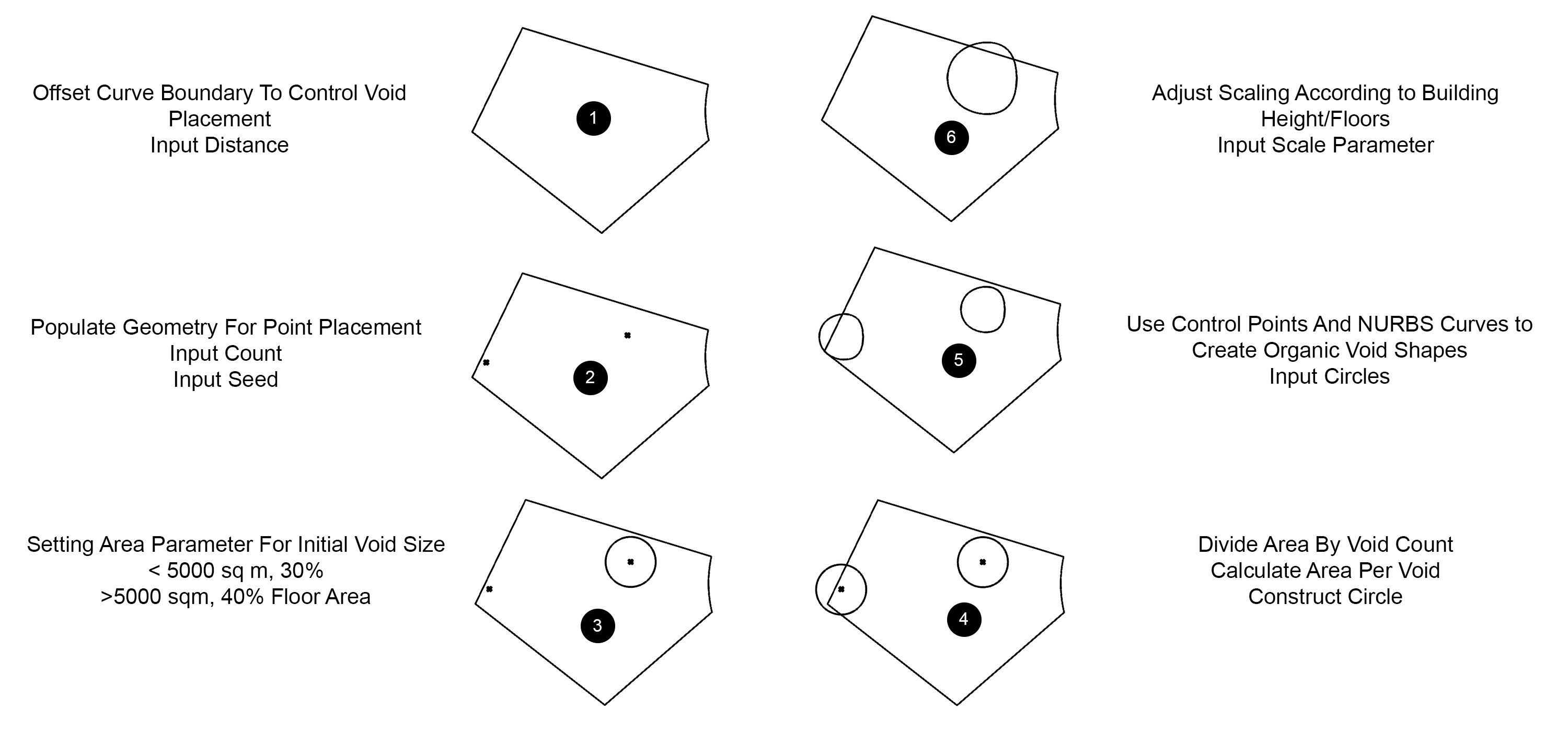
To accommodate aggregation, the mines are parametricly separated for residential and non-residential floors, for flexibility in placement and organization of facade.

Vertical Circulation
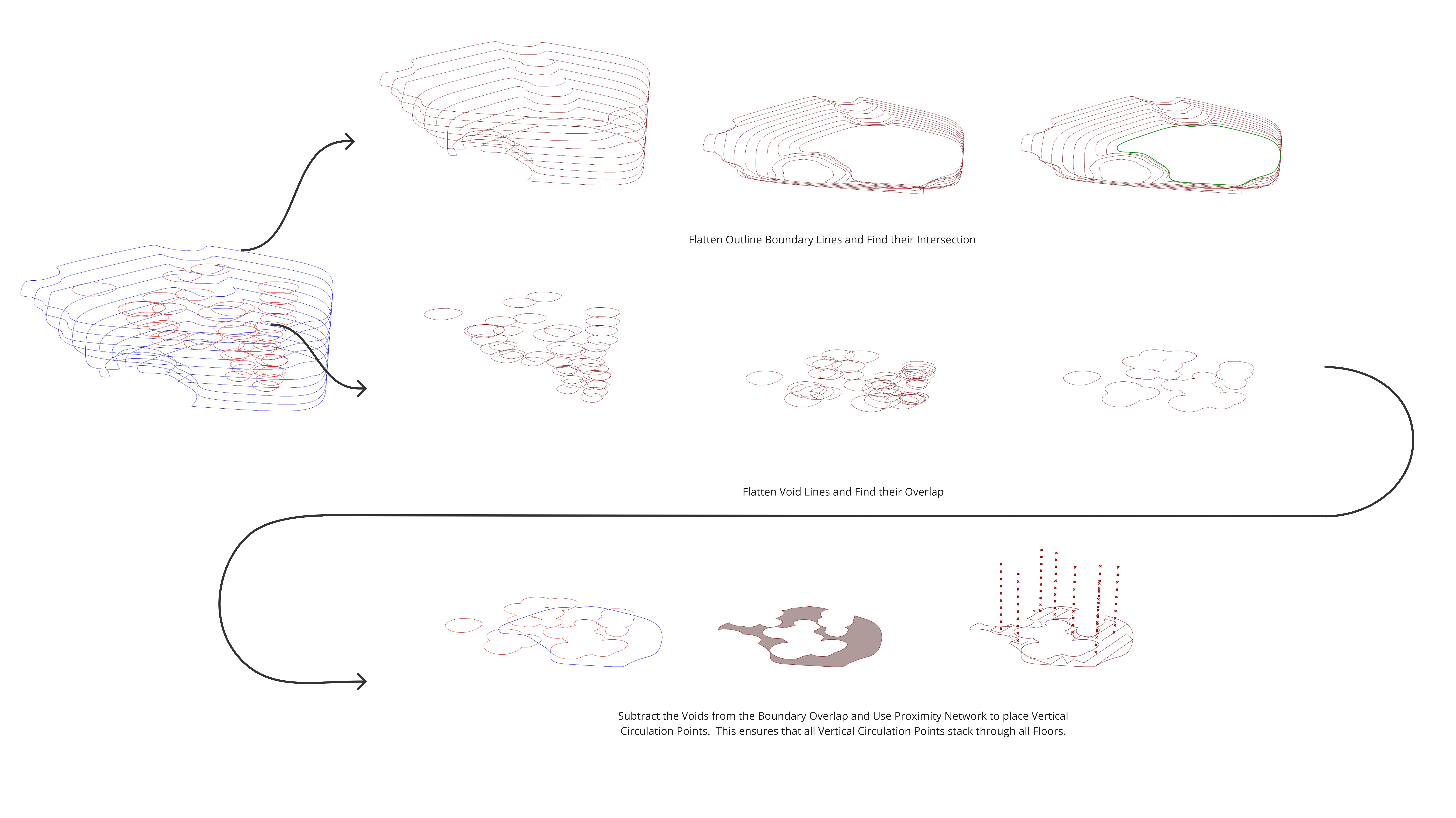
First we flatten our floor surfaces to identify overlapping area. Then, we generate a proximity network and average the connected points to determine our vertical core locations. Some vertical cores span the full building height, for egress, service/maintence and fire access use while others span only the residential or non-residential floors, to efficiently increase privacy as we go to top floors.

Horizontal Circulation
To generate the circulation, the following steps were followed:
- Assign vertical circulation points
- Assign gathering points around voids
- Assign junction points for corridors
- Fill in void boundaries to create continuous corridors
- Create corridors
These steps have been illustrated in the following diagram:

Program Definition
Percentages are assigned to each program function and distributed across floors proportionally. Residential and non-residential spaces are differentiated by tracking their respective floor indices, and we later use this program data in modular unit aggregation.
Modular Unit Definition
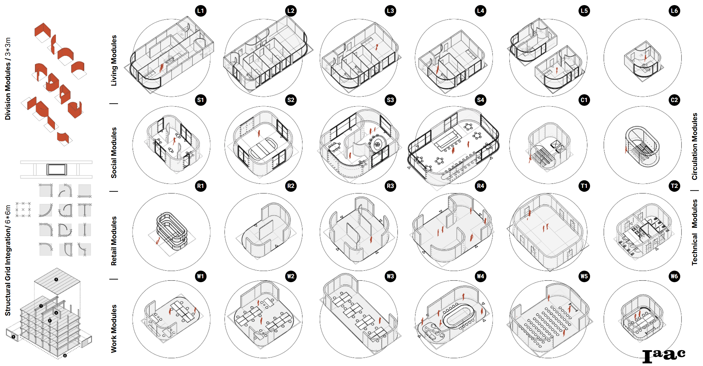
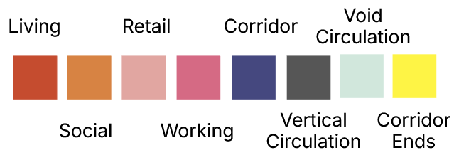
Our aggregation process uses modular units tailored to suit the floor programming types. These modules are categorized into functional groups, Living Modules, Social Modules, Retail Modules, Work Modules, Technical Modules, and Circulation Modules, each designed to meet specific spatial and program needs.
Living Modules provide residential space configurations with different scales and layouts. Social Modules cater to communal activities and gatherings. Retail Modules are compact and adaptable. And Work Modules offer flexible office and workspace layouts.
The Technical Modules house critical infrastructure and service areas, for smooth building operation, and the Circulation Modules facilitate vertical and horizontal connectivity with staircases and corridors.
These modular units integrate with the structural grid and we place them strategically to meet programming requirements of each floor.
Modular Unit Aggregation
We wrote our modular unit aggregation algorithm from scratch in Python to meet our strict requirements. The publicly available aggretion plugins for Grasshopper, such as Monoceros and Wasp, do not provide adequate control or consistent enough results.
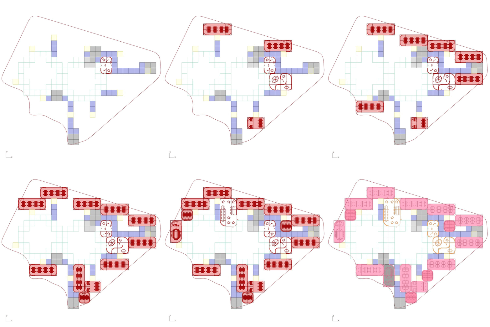
The aggregation step starts by assigning specific component types to points neighboring the corridors, determined by the program data for each floor.
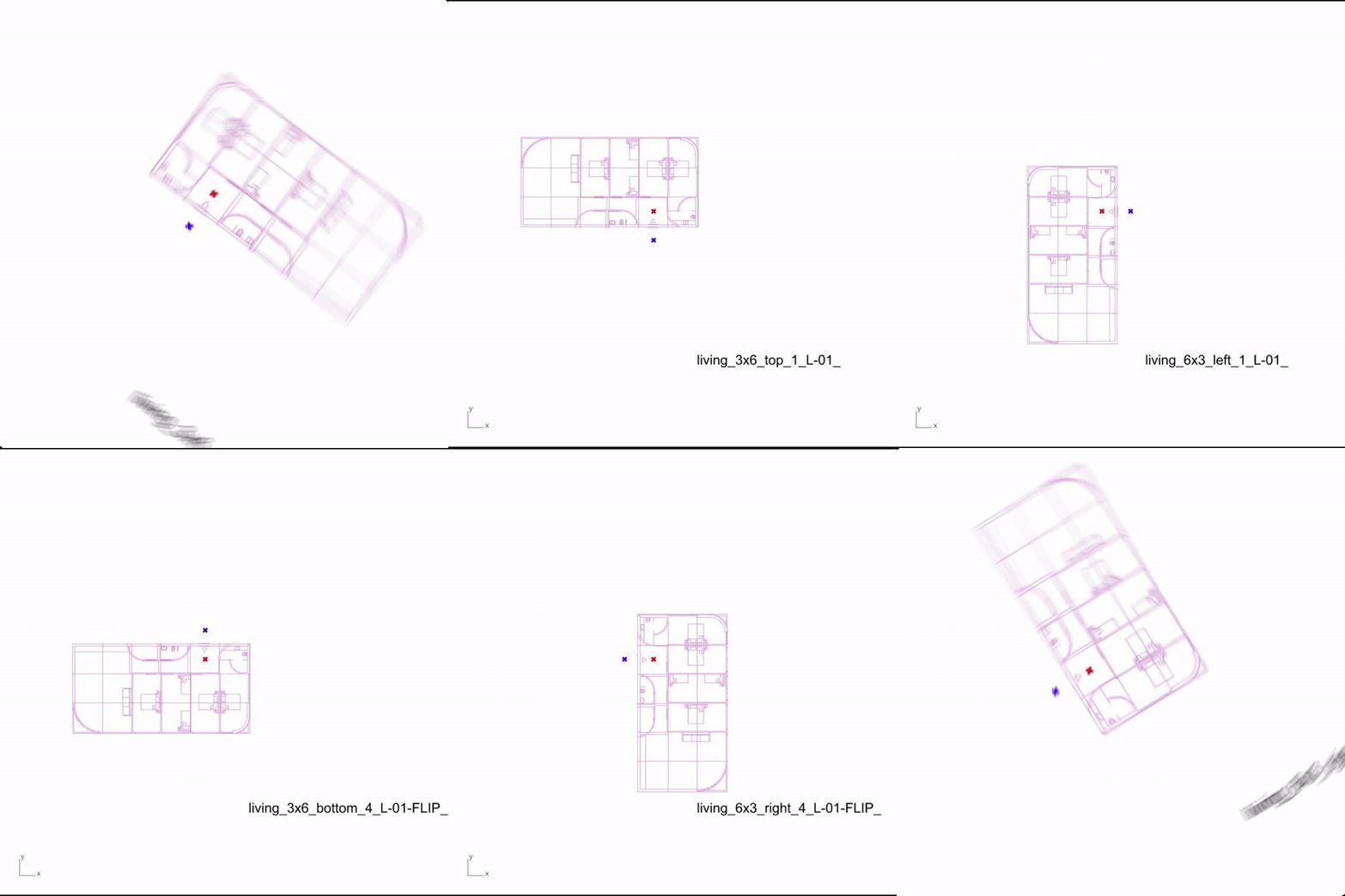
Units are tested at each point neighboring a corridor (matching program assignments) to evaluate suitability for placement, attempting to fill floor area with the largest units first. Units are rotated and flipped as needed to identify the most appropriate orientation. Iterative testing is conducted to finalize aggregation, and the results are recorded for further use. Each entrance of a modular unit definition is tested before testing the next modular unit.
The following rules govern module placement:
- Define maximum quantity of Modular Units to place for each unit type, ex. only place five S-03 units
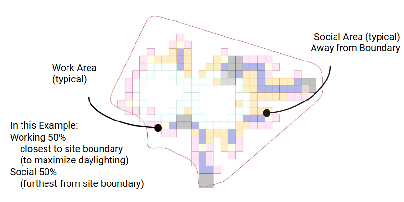
- Assign work and living units closest to building exterior (maximizing daylighting)
- Place units in neighbor points closest to void centers first
- Place units that match component type of neighbor point
- Fit largest possible unit first, testing eight orientations
- Unit entry must align with corridor
- Unit cannot overlap with corridors or already placed Modular Units

Optimization Challenges
Void-Circulation Optimization
Circulation corridors are strategically generated around the building voids, forming pathways for aggregation. These corridors are critical in defining the organization and connectivity of the modular units. To optimize the combined modular unit area and maximize usable space, various circulation offset distances were tested.

The analysis revealed that a 1-meter offset consistently produced the best results across all of our building iterations, generating the most dense modular units. As the offset increases to 5 meters, space is wasted between the corridors and the voids because modular units are too big to fit in this area.
As the offset increases, beyond 5 meters, modular units start to fit between the circulation and void, increasing area density.
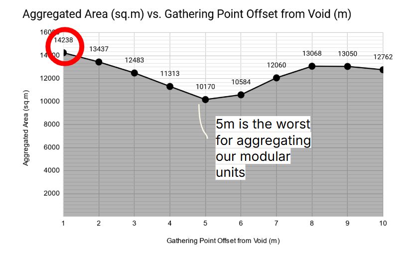
In expansive plots, offsets beyond 5 meters would likely provide higher aggregated areas than offsets below, however in our site context, this strategy is ineffective because of the outer floor boundaries.
Aggregation Optimization
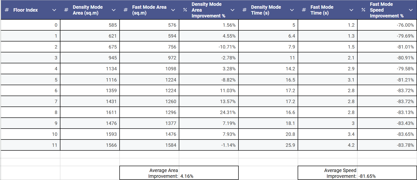
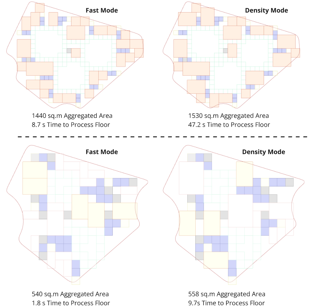
We develeped two distinct aggregation methods and evaluated their effectiveness. We call them Fast Mode and Density Mode.
In Fast Mode, all modular units are tested at each point within the circulation framework. This approach prioritizes computational speed, enabling designers to rapidly generate building models and explore different input scenarios. Despite its expedited process, Fast Mode maintains a high level of accuracy, making it ideal for iterative design explorations.
Density Mode tests all points for each modular unit, and focuses on maximizing spatial efficiency and density. This method offers a more detailed and comprehensive analysis of unit placement but requires exponentially more computational time than Fast Mode.
The comparative analysis highlights the suitability of Fast Mode for quickly prototyping and testing design variations without significant loss of precision, providing a versatile tool for early-stage decision-making.
Structural System
The core structural framework is based on a fixed 6m x 6m grid system, providing stability and uniformity. Within this grid, flexible partitions and components enable the transformation of the building’s interior and exterior spaces, ensuring versatility in its use.
The structural system utilizes a mass timber construction approach, emphasizing sustainability, efficiency, and adaptability. The primary framework is composed of Cross-Laminated Timber (CLT) suspended floor slabs and modular partitions, seamlessly integrated into a fixed mass timber grid based on a 6m x 6m layout.
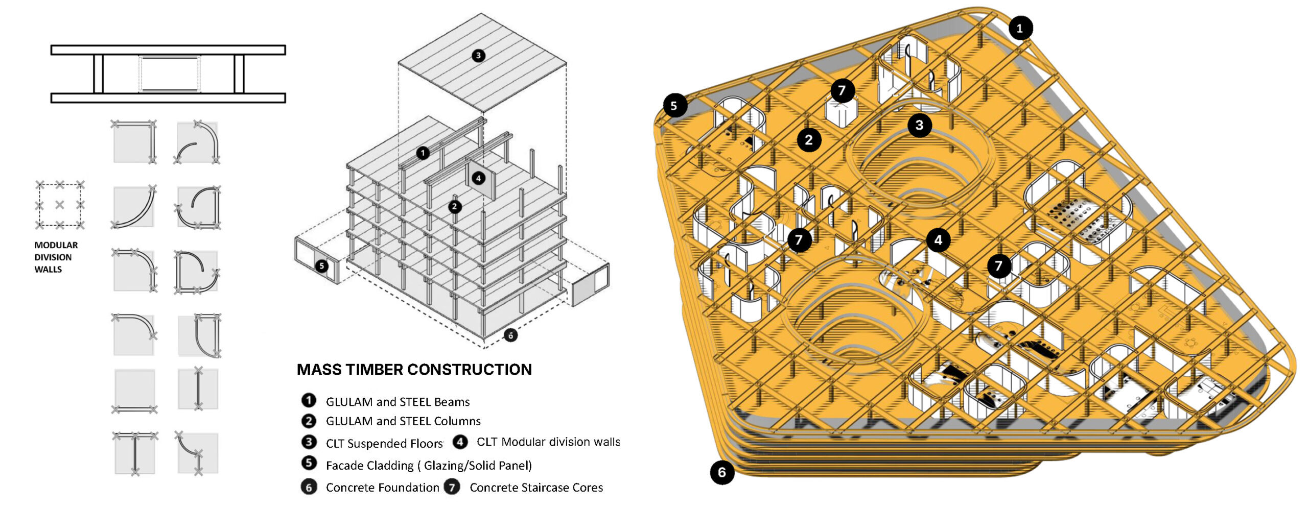
Additional detailing, analysis and optimization can be found in a separate IAAC Blog Post:
https://blog.iaac.net/analysis-of-generative-glulam-and-steel-beam-structure/
Facade Elements Canopy Openings
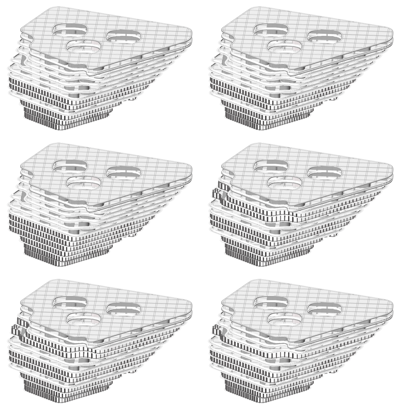
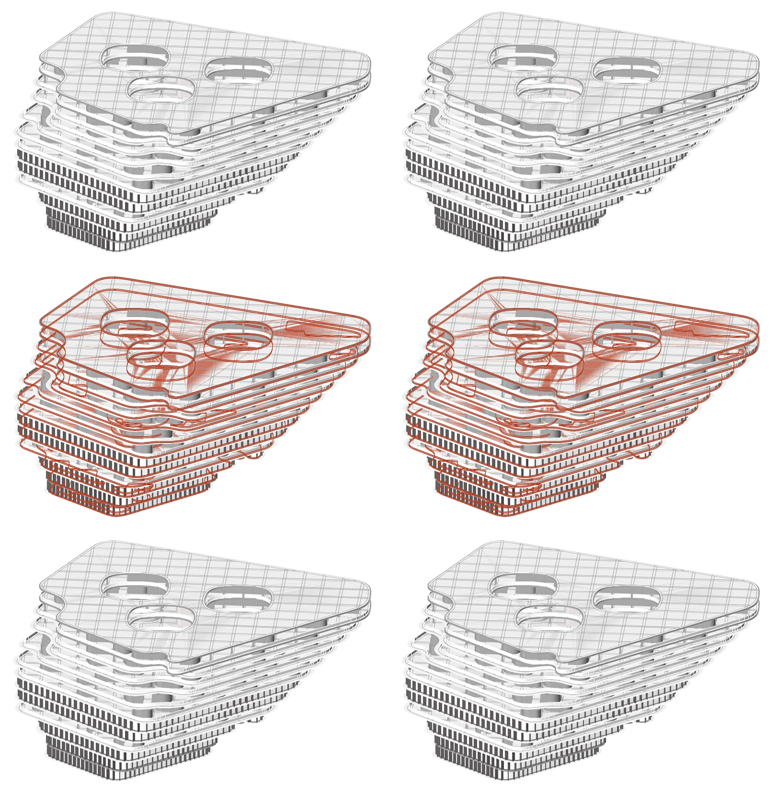
Façade characteristics are divided into two typologies, defined by the function assigned to each floor. Canopy openings are created by extracting the boundary of aggregated units on the relevant floor and intersecting it with the overall surface boundary of the floor. The openings are then selected and positioned based on the function of the respective floor and its relationship with the neighboring floors above and below.
Outputs
Building Instance
Input Spatial Requirements:
Retail + Social 50%
Living 50%
Program Output:


Building Plans
Ground Floor Plan:
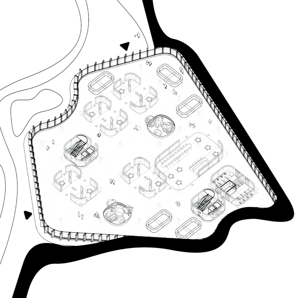
Residential Floor Plan:
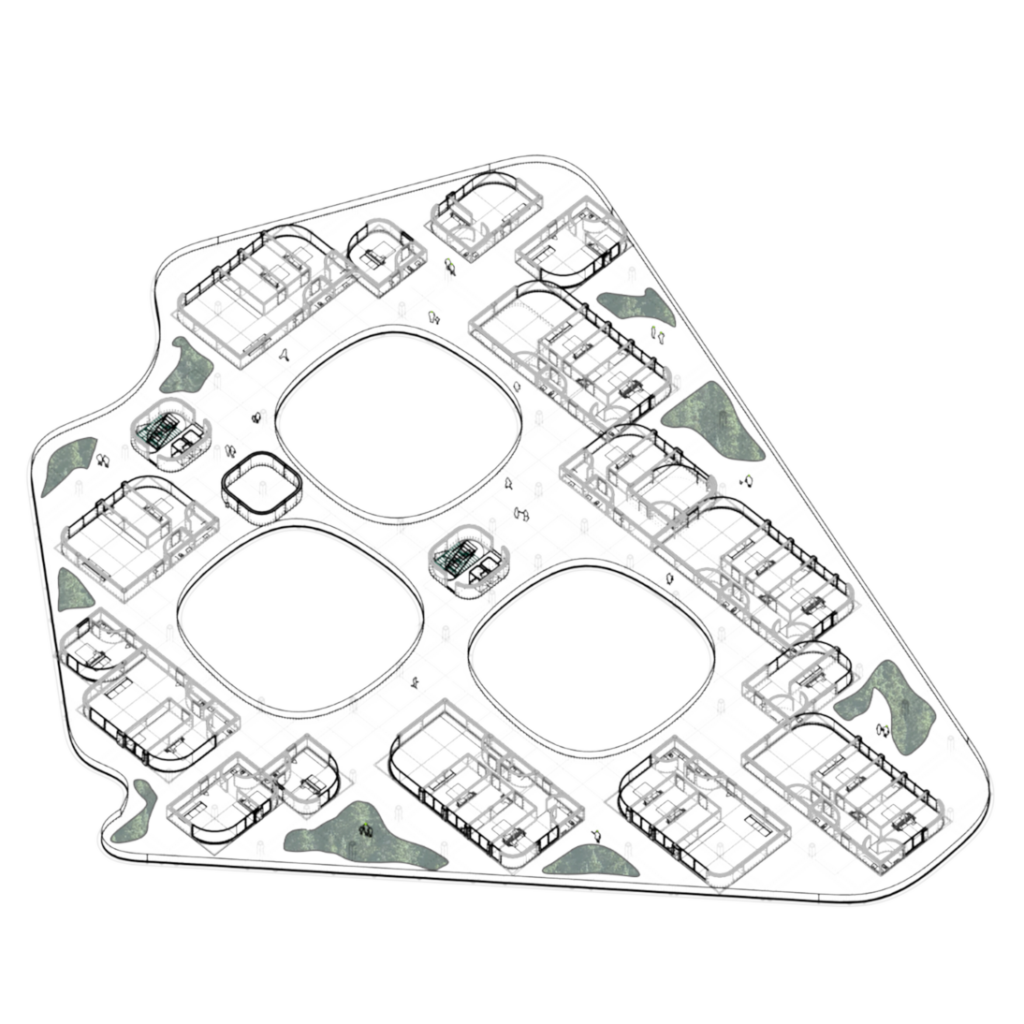
All Floors:

Low Density Building Iterations
Common Plot Iterations

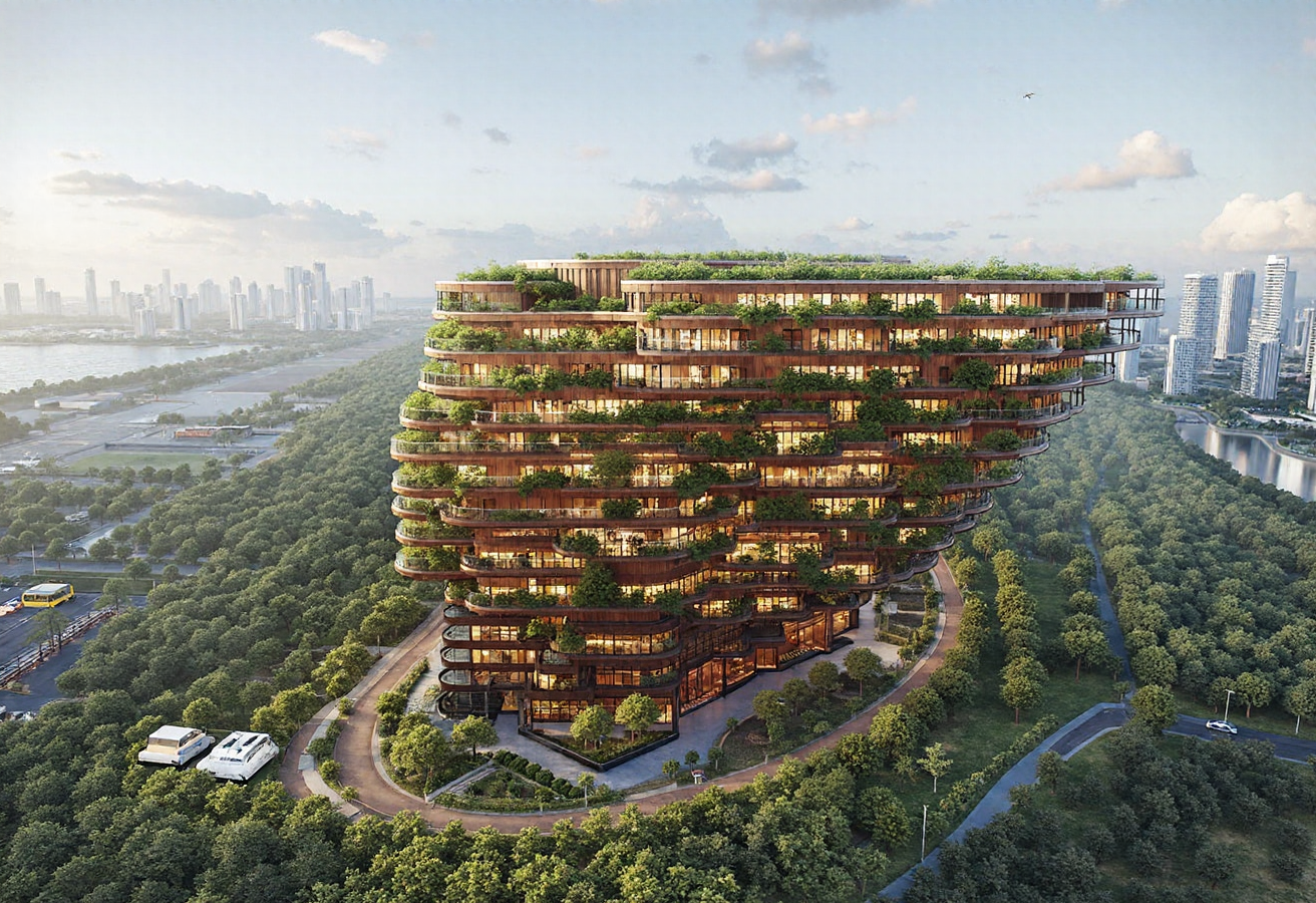
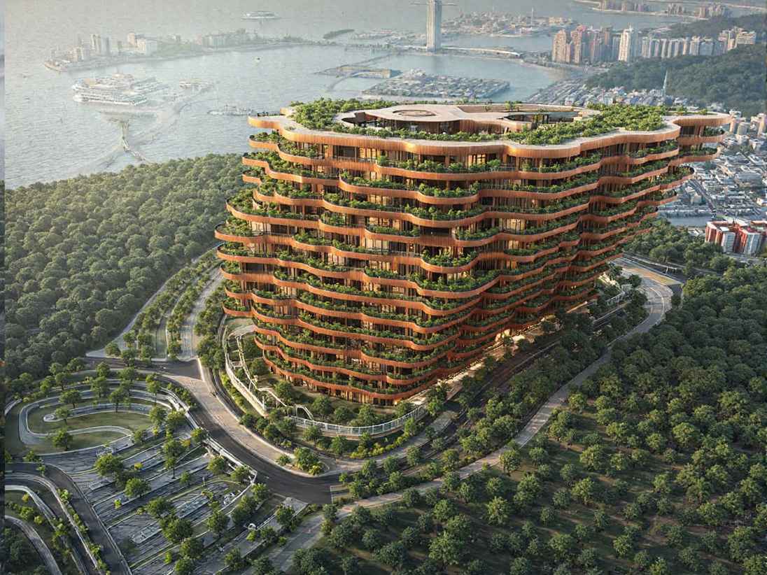
ComfyUI Generated Building Renderings
