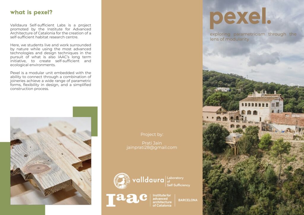
Research Topic:
How can a system of modular units embedded with the ability to connect through a combination of joineries achieve a wide range of reciprocal forms, flexibility in design, and a simplified construction process?
Keywords: design flexibility, reciprocal structures, interlocking joineries, efficient construction, modularity.
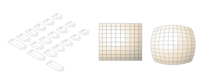
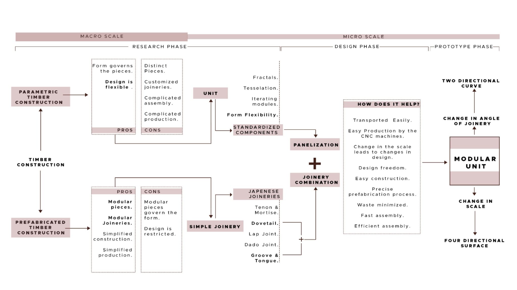
The tectonics of parametric architecture using timber primarily stem from two processes: mass customization and mass production. The first involves designing a form that is then entered into a digital script to generate the components, each distinct from the last and connected to the others using a customized joinery. This result is a structure with a complex assembly system. In the mass production method, the singular element is designed, which then governs the design of the form. The outcome is modular, and the element, or fractal, controls the design and form-finding processes. The techniques of the two systems contrast with one another, and both have distinct shortcomings.
How can each approach’s shortcomings be combined with each system’s advantages to achieve a workable solution? The first procedure offers the advantage of flexibility in form development, but the second process uses a modular element to simplify construction. How can a modular timber element embedded with the ability to connect through a combination of joineries achieve reciprocal structures, flexibility in design, and a simplified construction process? The outcome of this thesis would be the creation of a harmonic system of modular units connected by a set of joineries to help in designing a reciprocal structure without limiting the design or form-finding process. Additionally, prefabrication and streamlined construction procedures would enable design flexibility and simpler tectonics for timber construction.
Further research will focus on creating a collection of modules that can be quickly assembled and connected collectively and individually according to form requirements.
INTRODUCTION
Parametric Design
Parametric design is a technique in which engineers and architects use algorithms to create complex, customized products or structures. This process allows designers to input a set of parameters, or variables, that the algorithm then uses to generate a unique solution. This results in the design of components and joineries being different.
Prefabrication
Prefabrication is the practice of fabricating and assembling components of a structure in a factory or other manufacturing site and transporting complete assemblies or sub-assemblies to the construction site where the structure is to be located.
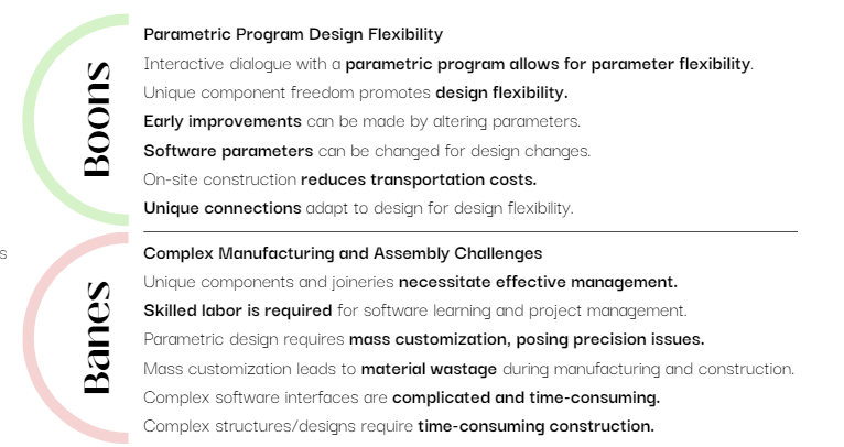
While parametric design offers numerous benefits in terms of flexibility and customization, it also presents significant challenges and drawbacks, particularly in terms of
manufacturing and assembly complexity, skilled labor requirements, precision issues, material wastage, software usability, and construction timelines.
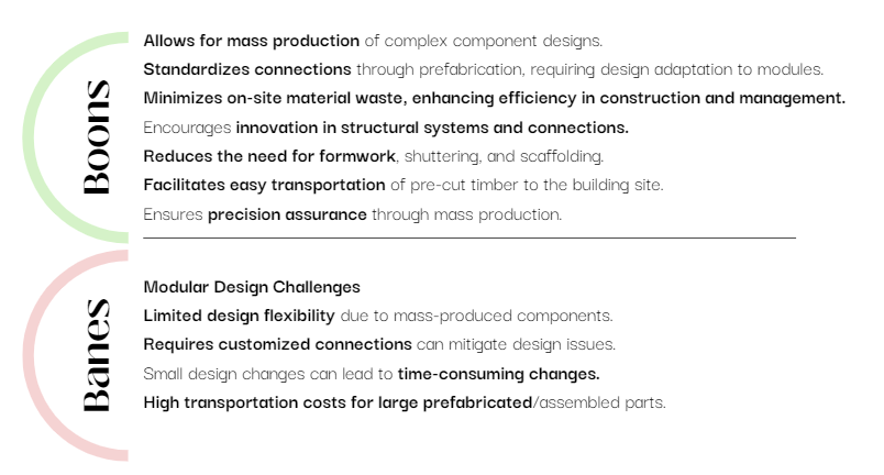
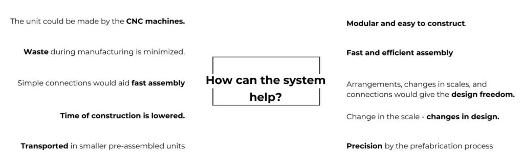
Prefabrication offers a range of benefits, including efficient mass production of complex components, standardized connections, reduced material waste, and innovation in structural design, decreased reliance on temporary support structures, ease of transportation, and precision assurance through controlled manufacturing processes.
HOW CAN THE BOONS OF PREFABRICATION SOLVE THE CHALLENGES FACED IN TIMBER PARAMETRIC ASSEMBLIES?
STATE OF THE ART
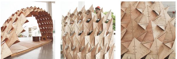
Modular/Standardized Element Practice
This design process creates adaptable, effective, and sustainable architectural solutions by fusing parametric principles with modularity. Creating standardized architectural elements or modules that are simple to install and disassemble is known as modular design. Although building can be completed quickly and efficiently using this method, design freedom is not possible because the form’s design must accommodate the module’s geometric constraints.
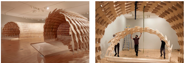
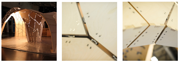
Customized/Non-standard Element Practice
Non-standard element practice in timber parametric design refers to creating structures or buildings using specially made, one-of-a-kind, or unusual timber elements.
Rather than depending on generic, off-the-shelf wood parts, designers make custom pieces that are suited to the unique needs and limitations of a project. Designers are free to produce one-of-a-kind, distinctive constructions that might not be possible with conventional components. This method enables the realization of intricate, visually beautiful designs and promotes architectural innovation.
The utilization of non-standard elements in timber parametric design presents significant advantages concerning design adaptability, performance enhancement, and visual appeal. It does, however, also come with difficulties in terms of price, complexity, availability, construction, and regulatory compliance.
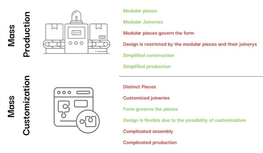
Mass production vs. mass customization
Prefabrication processes and parametric design are very large concepts, A detailed analysis through state-of-the-art projects was done to understand how the standardized and non-standardized element system could take the positives of both to position itself in their respective worlds. This helped narrow the scope or aim of this system.
Modular element practice leads to mass production. On the other hand, customized element practice leads to mass customization. After understanding the positives and negatives of both concepts, a comprehensive design would be designed to solve the negatives of each of these concepts.
HYPOTHESIS
The thesis problem is to overcome the shortcomings of parametric design and prefabrication in timber buildings, namely in terms of design adaptability and construction
efficiency. While parametric design provides freedom and the ability to build complex shapes, it frequently lacks efficient construction solutions that can effortlessly transfer these plans into reality, particularly when working with timber.
There is a need for a systematic strategy that solves these shortcomings by establishing guidelines for parametric timber building. This approach should allow for the creation of interconnected, self-supporting reciprocal structures while simplifying the construction process with standardized components and joineries.
Thesis Proposal: Modular Units with Connective Abilities
- Proposal for modular units with adaptable joineries for various design requirements.
- Incorporation of parametric principles for diverse and complex forms.
- The system allows for flexibility in design, allowing easy adaptation and customization.
- Streamlined construction process through standardized components and precision
prefabrication techniques. - Minimizes on-site assembly time and reduces construction waste.
- Standardized joineries ensure consistency and compatibility, enhancing construction
efficiency
Thesis Statement
How can a system of prefabricated modular units be embedded with the ability to connect through a combination of joineries to achieve reciprocal interlocking, self-supporting structures, flexibility in design, and a simplified construction process?
METHODOLOGY
DESIGN
Joineries
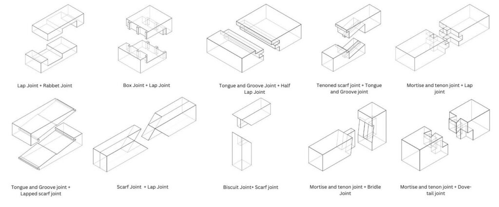
The research was conducted on traditional timber joineries, with a special emphasis on the difficult process of designing them at various angles. The practicality of using modern carpentry equipment and machinery to prototype these joineries was thoroughly investigated, with an emphasis on combining Japanese joineries to improve connection strength and security. As a consequence, nine distinct combinations were created, utilizing the best of both old workmanship and modern processes. This attempt represents a harmonic blend of traditional craftsmanship and modern invention, with the potential to change timber joinery processes by improving structural integrity and assembly feasibility.
Joinery Alteration
To achieve a parametric form, it was decided to modify the joineries while keeping the timber components modular. A systematic approach was established to alter each joinery combination in 10 degrees. Initially, the joinery’s contact surfaces were identified, and these surfaces were cut at an accurate 10-degree angle. The section removed by this cut was then attached to the other end, effectively completing the angle change. This process maintained the modularity of the timber pieces while allowing the design of dynamic and adaptive structures with parametrically angled joineries.
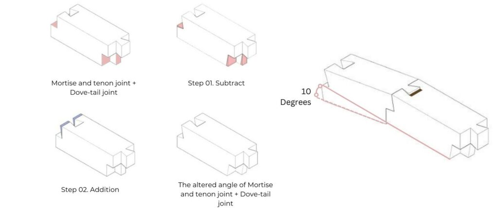
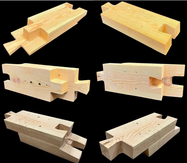
The joinery was fabricated in two halves for ease of fabrication and then attached using screws. Additionally, the roughing cut was used to fabricate the angular surfaces. The successful fabrication of this joinery combination was further developed in the research.
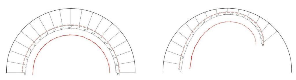
Scale Alteration
The evolution of the joinery combination expanded to include changes in the curvature of the arch, which were accomplished by varying the scale or length of individual elements. A modular technique was used to provide for an additional 10 degrees of curvature angle change by simply increasing the module’s length by 1 cm.
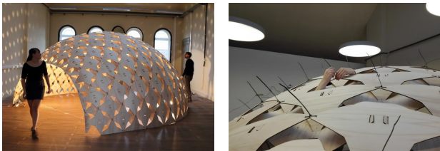
Reciprocal interlocking system
The principle of reciprocity is based on the use of load-bearing elements that, supporting one another along their span and never at the extremities, compose a spatial configuration without any clear structural hierarchy (Pugnale and Sassone 2014).
In this approach, planar components were considered while developing reciprocal systems. Circular tiles, squares, triangles, and more articulated or irregular geometrical shapes are all suitable options. When reciprocal structures are constructed of elongated parts, design efforts are primarily concentrated on three aspects:
(1) defining the fans to be assembled,
(2) investigating their composition options, and
(3) selecting the jointing system(s).
Materiality and jointing systems are intrinsically enhanced by planar elements; width andthickness open up new design possibilities, allowing designers to use surfaces rather than bars
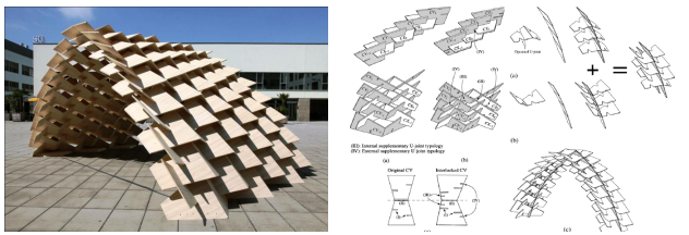
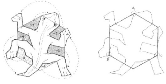
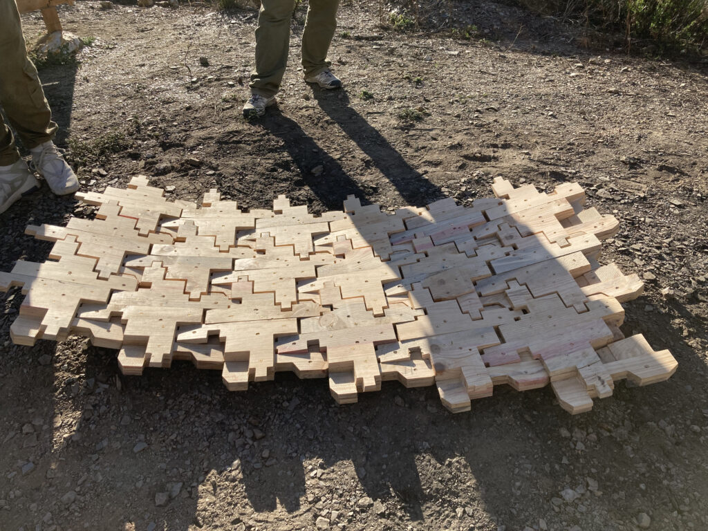
Drawing inspiration from M.C. Escher’s captivating interlocking patterns and Einstein’s geometric tiles, an innovative method was created to transform regular shapes into repetitive elements capable of generating both open and closed weaves. The unique approach allows for the incorporation of these elements into the joinery combination, resulting in a repeated interlocking module. Using this module, self-supporting reciprocal structures can be cleverly created, embodying a blend of joinery and structural innovation. Moving forward, a module was designed and then infused with Mortise and tenon joint +Dove-tail joinery combination to design a self-supporting reciprocal timber structures.
arrangements.
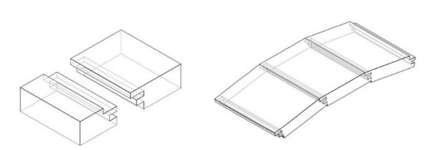
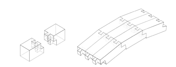
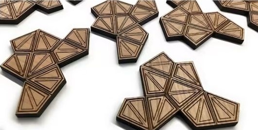
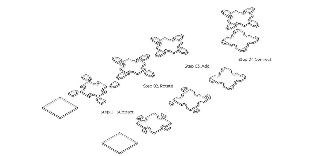
Module Design
A methodical strategy is provided for the design of the module.
1. First, choose a regular shape that meets the intended design aesthetic and structural criteria.Next, an acceptable joinery combination is determined, taking into account stability, strength, and aesthetic appeal.
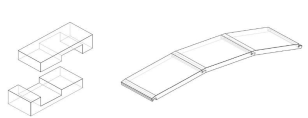
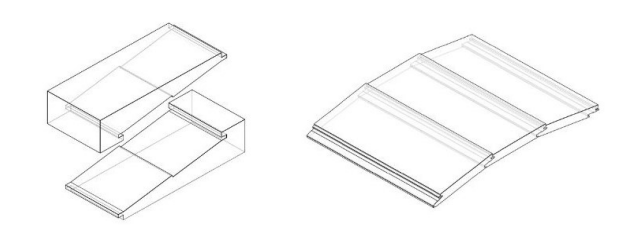
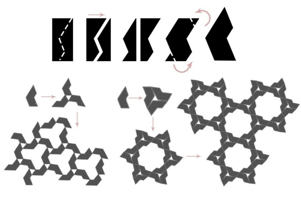
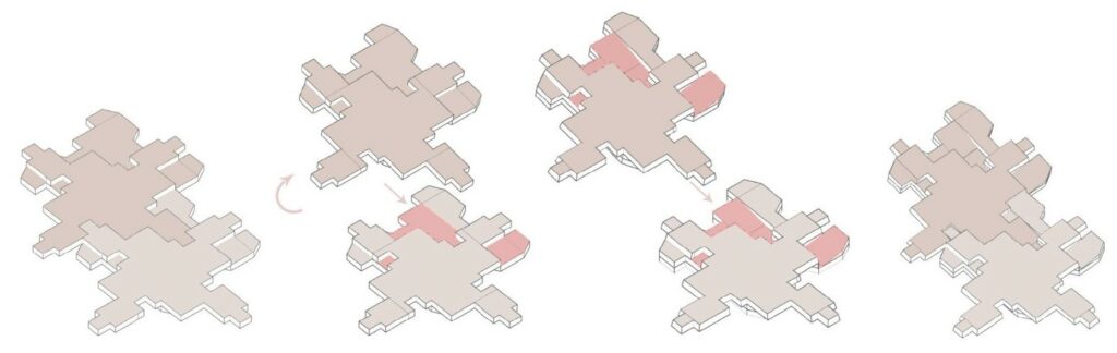
2. The selected joinery is then subtracted from the desired shape, yielding discrete parts.
3. These parts are rotated identically to provide uniformity and consistency across the module.
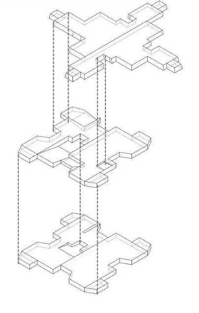
4. The removed pieces are then reattached to the design, ensuring a flawless fit that allows for interlocking when several modules are linked. This technique is done for both joinery combinations, yielding two separate panels.
Finally, these panels are aligned to best accommodate both joineries, ensuring optimal structural integrity and coherence.
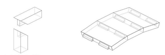
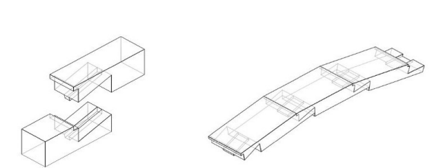
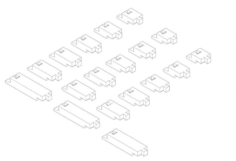
Module Alteration
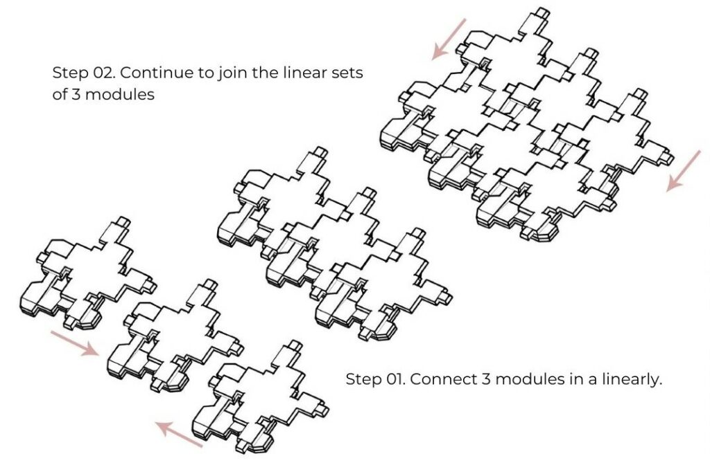
Module Assembly
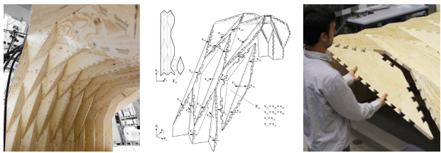
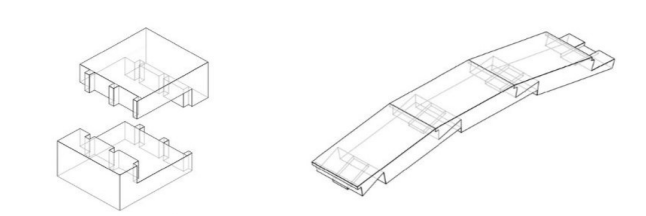
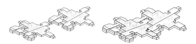
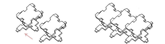
Following the modification of the module to support angular joineries, extensive testing was carried out to establish the most effective manner of joining the modules. Two main layouts were investigated: the latitudinal angular arrangement and the planar longitudinal arrangement. The latitudinal angular arrangement connects modules at an angle along their lateral sides, which improves structural stability and load distribution. In contrast, in the planar longitudinal arrangement, modules are attached along their longitudinal faces, resulting in a planar joint that enhances the structure’s ability to develop longitudinally.
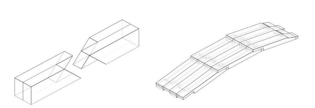
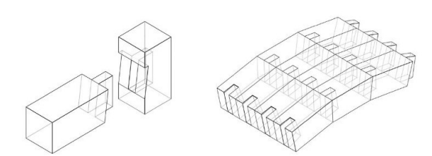
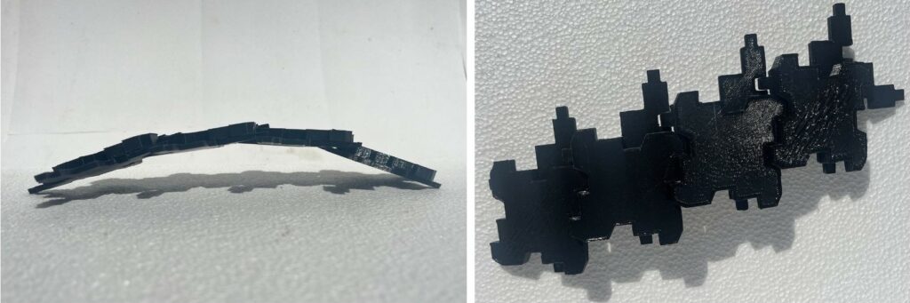
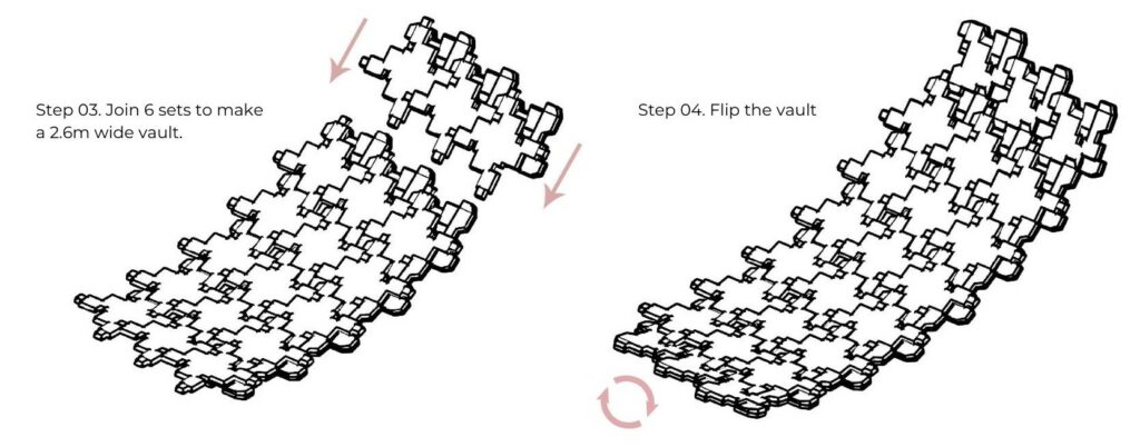
Singly-curved surfaces
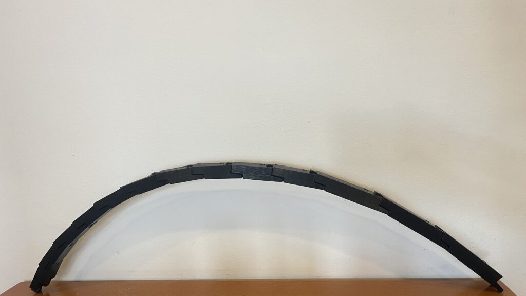
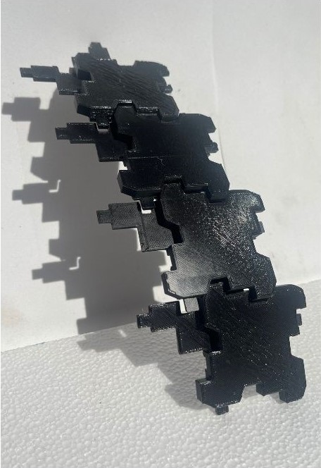
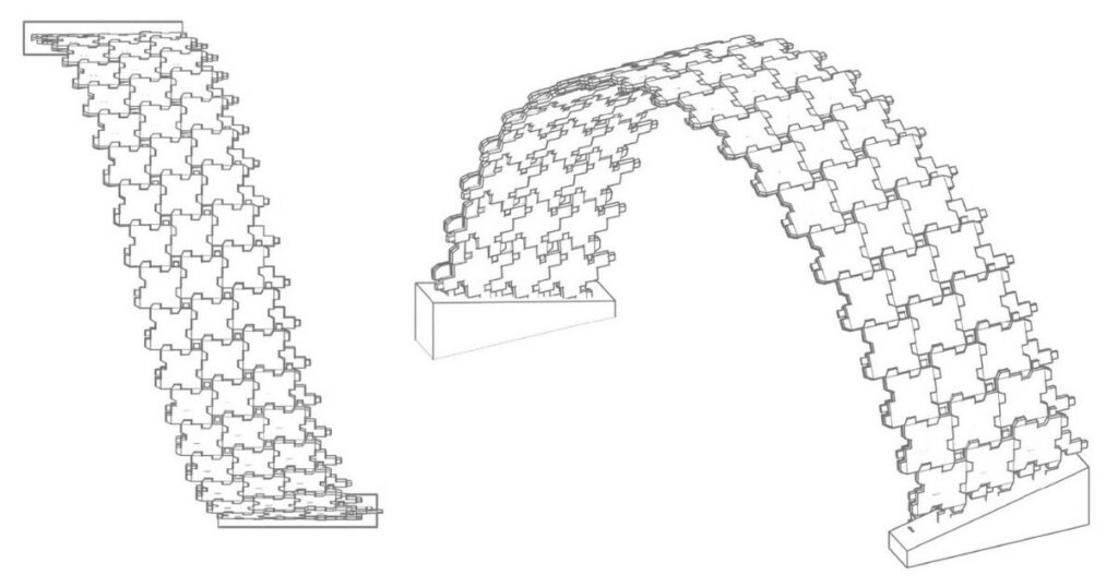
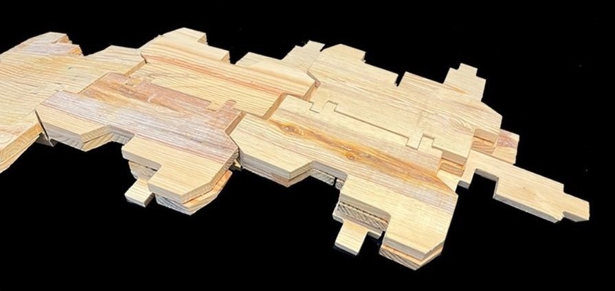
The planned module was then downscaled and 3D printed to allow for joinery and arrangement testing. As the module’s components were coupled, it became clear that it could form a self-supporting reciprocal vault under torsional stress. This means that when subjected to torsion, or twisting force, the interconnected modules maintained structural stability and integrity, resulting in a cohesive and self-supporting vault-like structure.
FABRICATION
Adaptation to Wood products
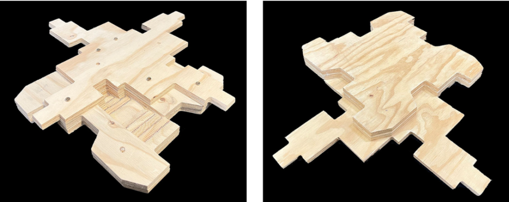
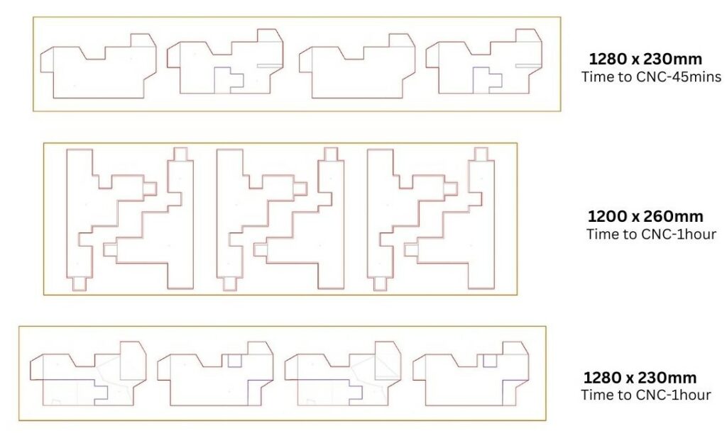
The module’s fabrication process was initially tested with plywood, providing insights into the complexities of the production process and allowing for a better grasp of the changes required when working with diverse woodboard materials. The focus then moved to modifying the fabrication method to meet timber lamellas and their inherent size limits. To maximize productivity and reduce material waste, the three module portions were cut in half, allowing for simpler nesting of the pieces during production.
Tolerance Testing
During the testing phase of the fabrication process, considerable difficulty occurred in terms of joinery tolerance. To address this issue thoroughly, prototypes were made using CNC machining and 3D printing technology. These prototypes were rigorously tested with tolerances of 0.25mm, 0.5mm, and 1mm to determine their performance and durability. It was discovered that the 0.25mm tolerance produced the best results in terms of joinery precision and structural integrity. As a result, the final CNC files were designed to maintain this ideal tolerance, assuring the accuracy of the joineries during fabrication.
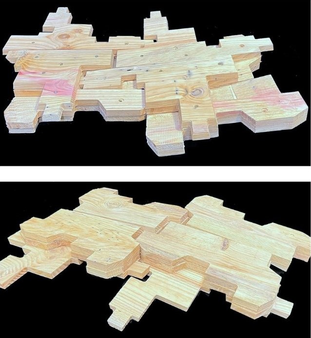
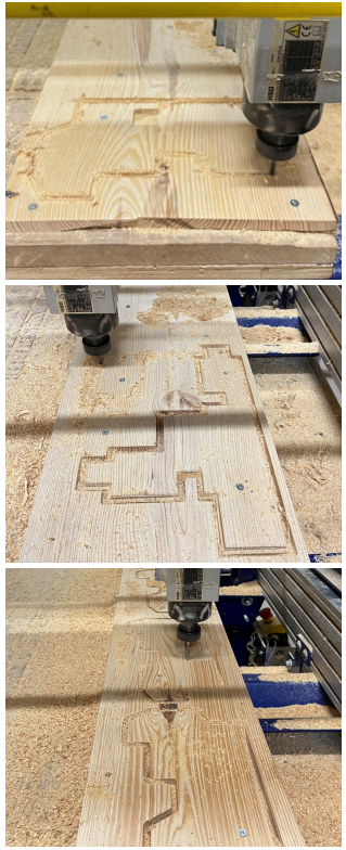
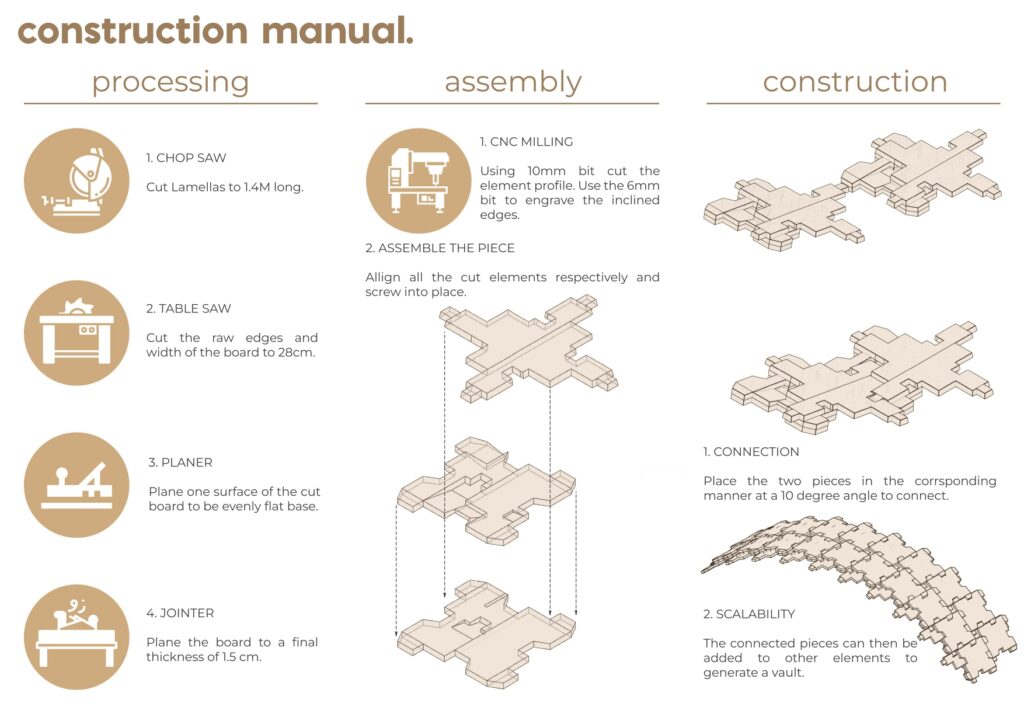
Wood Processing and CNC File preparation
A precise fabrication procedure was developed to create two modules, each of which consisted of two lamellas measuring 1280mm by 230mm and one lamella measuring
1200mm by 260mm, all with a thickness of 15mm. The modules’ exterior cuts were made with a 10mm drill bit to ensure accuracy and consistency in dimension. A 6mm engraving tool was used to make the roughing parallel finishing cuts required for the joinery, ensuring precision and uniformity. Two complete modules could be manufactured in three hours thanks to efficient processing, which optimized manufacturing time and resource use. To prepare for the RCA workshop and facilitate mass production, a total of 24 complete modules were manufactured according to specified fabrication standards, maintaining quality uniformity throughout all units.
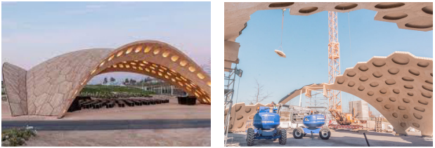
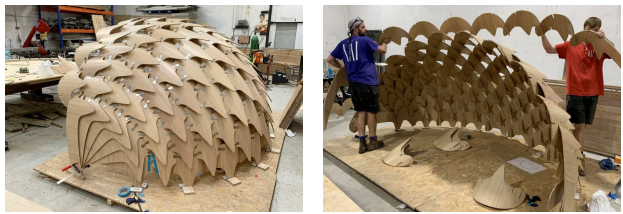
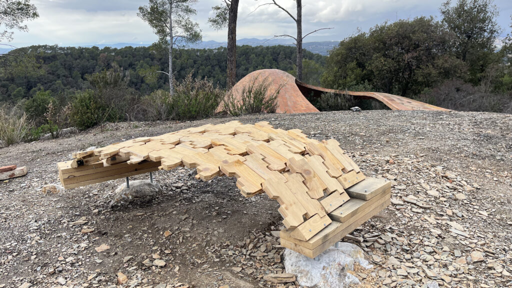
RECIPROCAL TIMBER AND STONE WORKSHOP
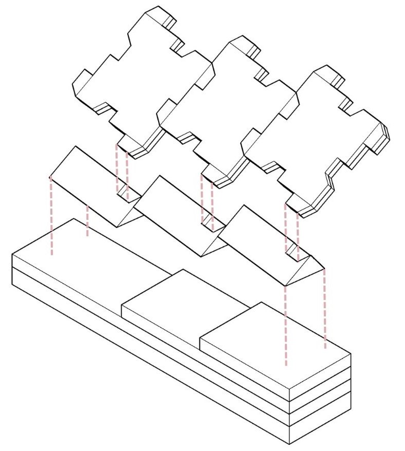
Vault Assembly Manual
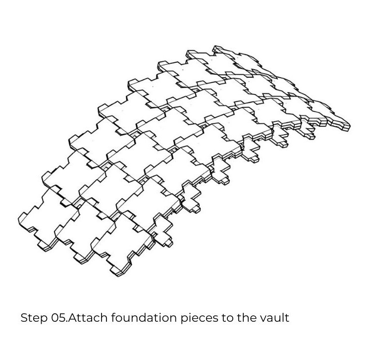
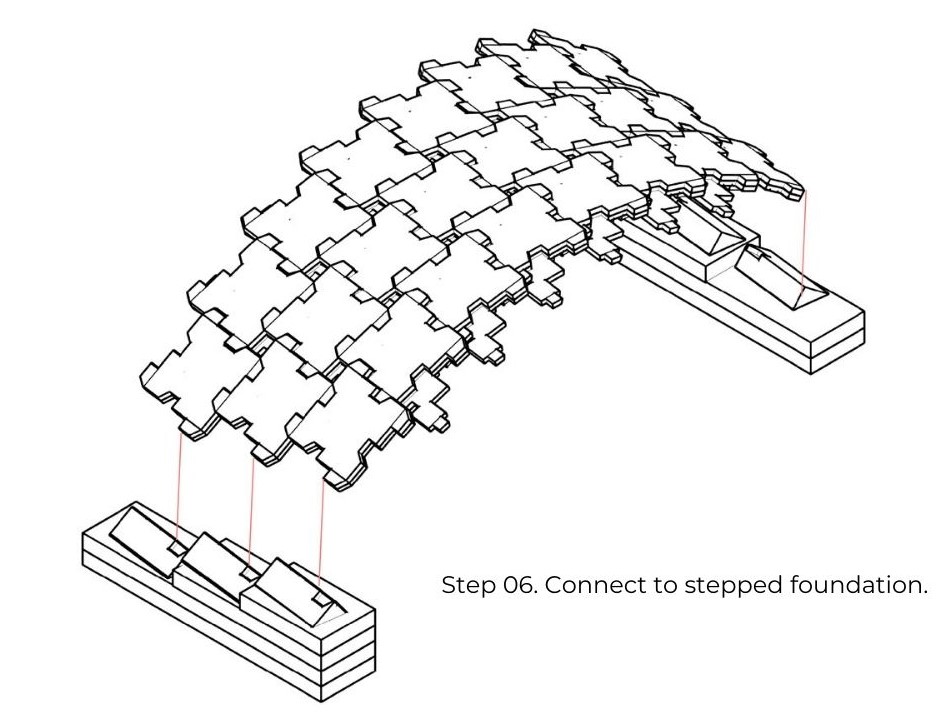
Foundation Design
Royal College of Art Collaboration: February 26, 2024
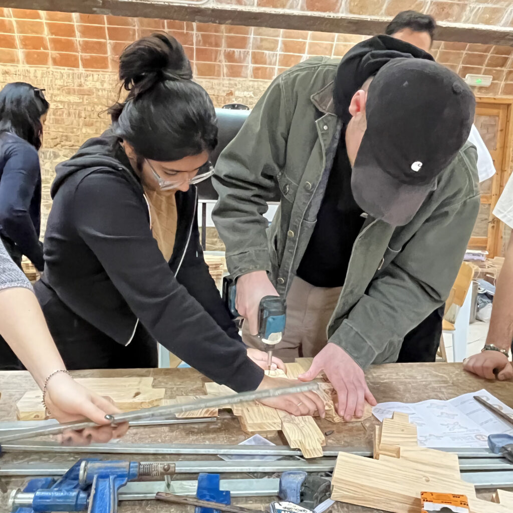
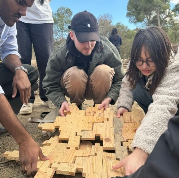
Observations during the workshop
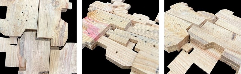
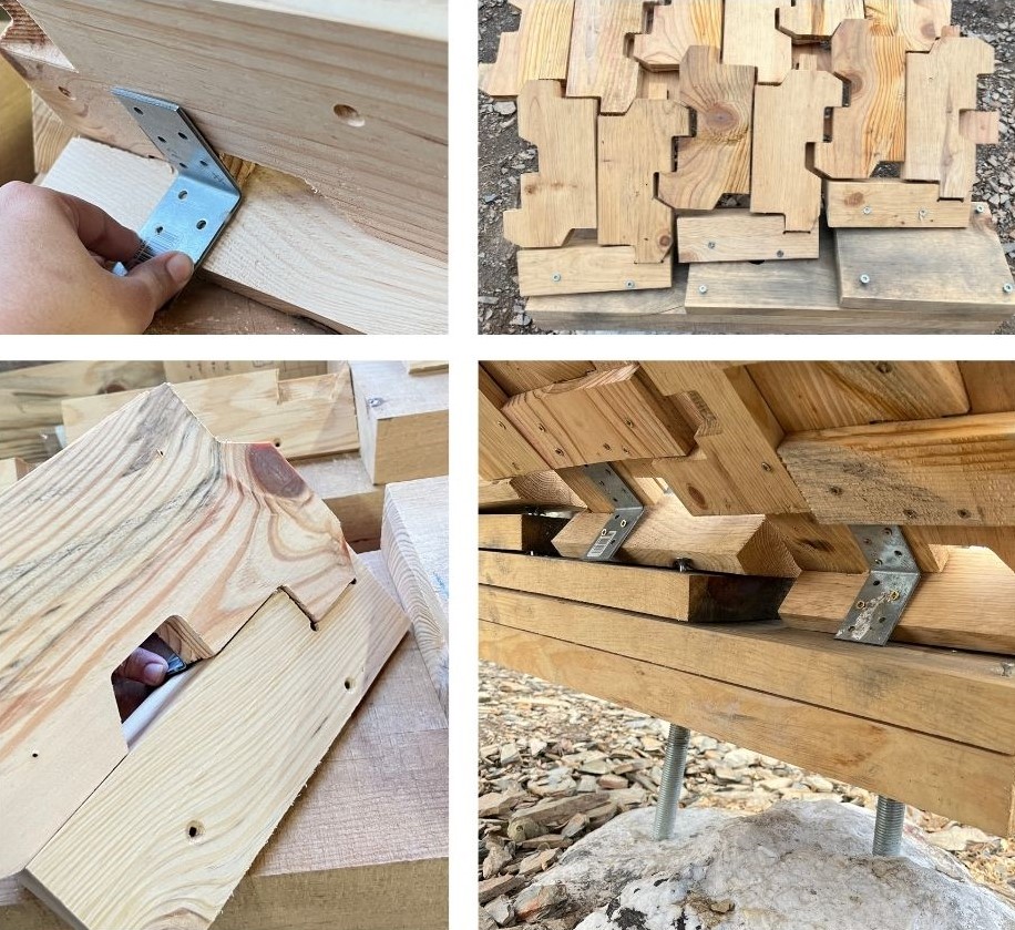
1. A significant issue develops during the assembly of the module parts, mostly due to the existence of knots in the wood and the thickness of the screws utilized. Furthermore, the screw thickness may not be appropriate for the type of wood used or the intended use, causing additional stress on the material and increasing the probability of fracture.
2. Errors in module alignment and pre-assembly can cause gaps in the middle of the constructed module. These gaps are caused by misalignment or incorrect fitting of individual components during the assembly process. When modules are not properly aligned or pre-assembled, discrepancies in component arrangement occur, causing them to not fit together flawlessly.
3. Furthermore, if the modules are not correctly clamped during assembly, their alignment may be affected. Misalignment can develop due to uneven pressure distribution or insufficient support, resulting in uneven joints and structural instability.
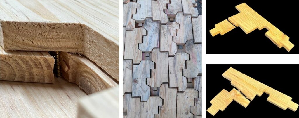
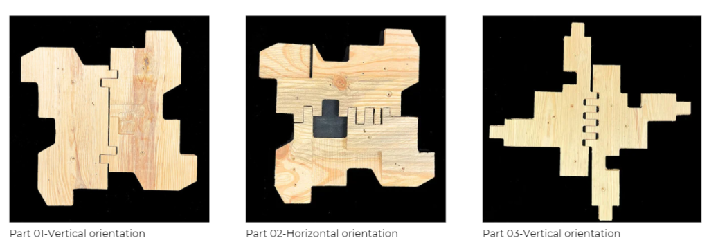
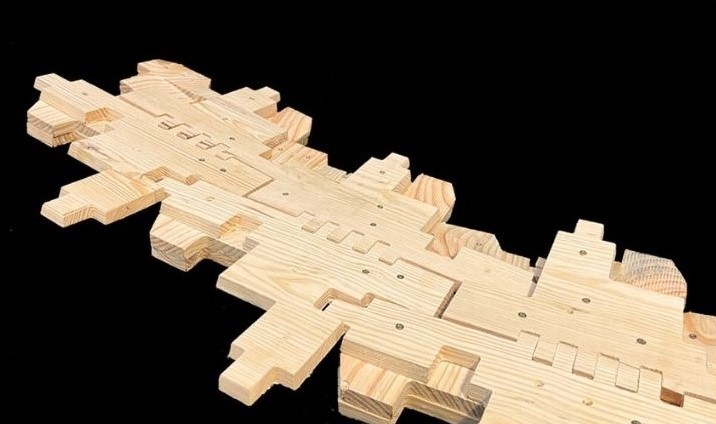
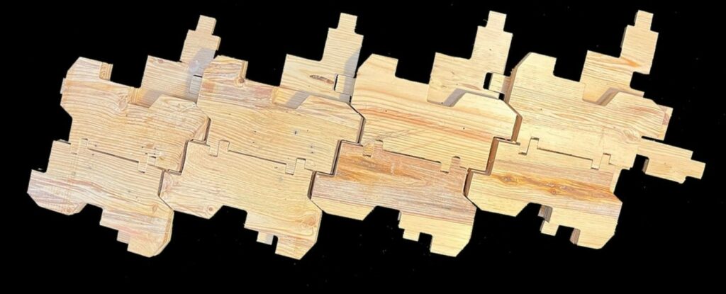
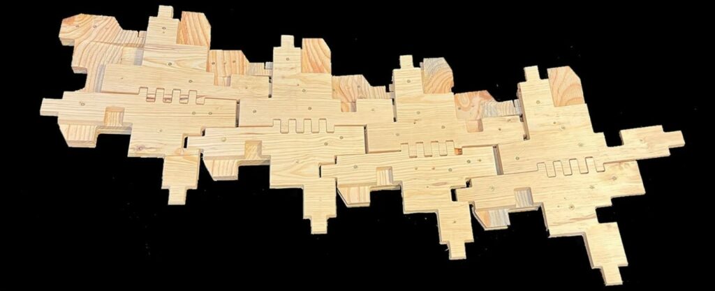
FINAL PROTOTYPE
To improve the individual connections within the module and handle alignment concerns, the design was updated to include finger joints. These joints improve the surface area for bonding, resulting in stronger and more secure connections between module components. Furthermore, to optimize the pre-assembly process and reduce alignment mistakes, the direction in which the module’s parts were cut was carefully altered. The top and bottom layers were vertically arranged, with the center layer split horizontally. This adjustment guarantees that the components fit more naturally during assembly, lowering the possibility of misalignment and closing gaps between the sections.
FUTURE IMPLEMENTATION
Future development plans include a focus on broadening the research on joinery combinations and modules to produce a diverse range of reciprocal timber structures. Exploring additional joinery techniques and experimenting with different module configurations has the potential to open up a world of design options and architectural expressions.
Furthermore, the scaled modules provide an intriguing opportunity to investigate their adaptability to transitional surfaces, allowing for the production of two-directional surfaces within timber structures. This unique technique not only broadens the design options but also improves the versatility and functionality of timber structures, paving the way for the creation of dynamic and complex architectural forms.