
At the request of STORE STORE in London, we developed a proposal for a timber structure roof for an existing garage located specifically in Clissold Crescent, Hackney.
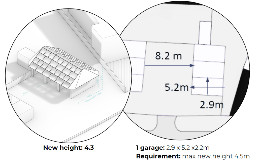
The objective is to transform the space into a workshop. The project presented a unique challenge as it is planned in phases, necessitating a demountable design that can be reused in a different building with varying dimensions. The proposal focuses on easy assembly and disassembly. The client emphasized the importance of allowing natural light into the space and increasing the existing head height. Additionally, the construction of the roof will be undertaken by a local team of young students from the community. This community involvement adds a dynamic aspect to the project, making it a collaborative effort with the potential for skill development among the local youth.
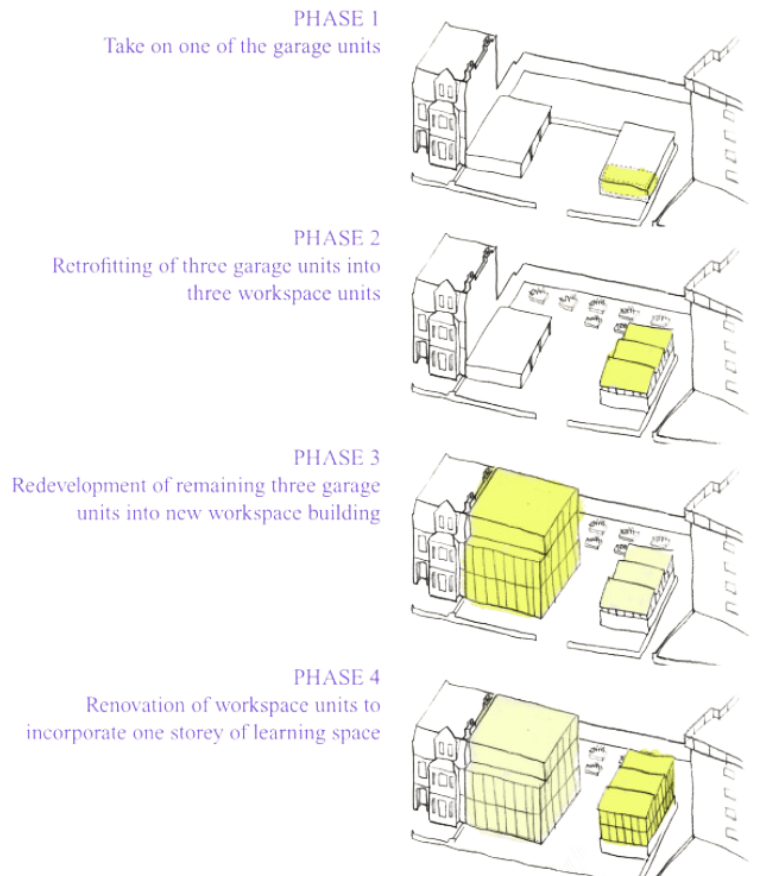
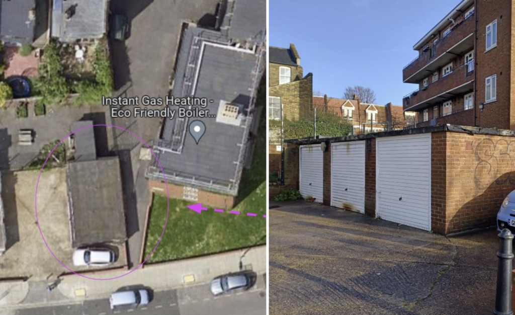
Image of the location and existing garage, pertaining to phase one of the project
Design Concept – Inspired by the simplicity of easily assembled, stackable structures
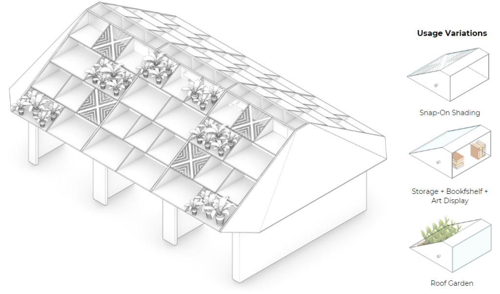
This modular “stacked-boxes” design streamlines the processes of disassembly and reassembly, allowing the roof to be adaptable to diverse locations and requirements.
The shelves provide ample storage, maximizing the utility of overhead space. Those same shelves are also utilized as outdoor planters to create a roof garden, infusing nature into the interior and offering shade. Additionally, the exterior “snap-on” shading elements serve a dual purpose: they act as a protective solar shield while simultaneously diffusing light.
I. Preliminary Design Exploration
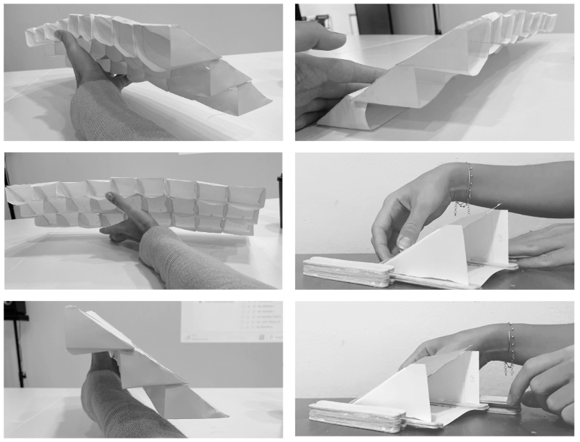
Prototyping Process
Images of the prototyping process for a roof that doubles as shelving. Independent modules were crafted, designed to be stacked upon one another. Initially, a slide-in model was conceived, where elements would slot together. This initial concept laid the groundwork for a refined design, which evolved into a lateral support structure. In this improved version, the boxes are placed between full side planes, enhancing the stability and functionality of the shelving system when integrated into the roof design.
II. Analysis and Design Evolution
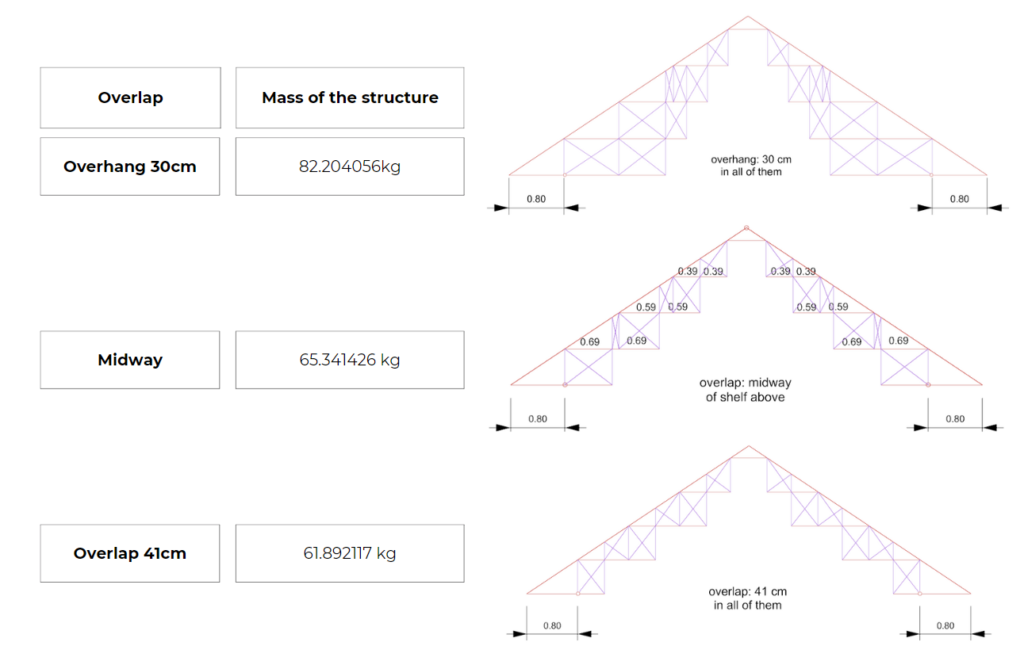
Through the use of Grasshopper for Rhinoceros and analysis simulations conducted with different structural configurations using the Karamba 3D plugin, we tested the performance and structural efficiency of various shelf overlay designs. We explored alternatives with a 30cm overhang between stacked boxes, overlap at the midway point of each box, and a 41cm overhang from the edge in a cantilevered box arrangement.

1. Testing Overlap
The arrangement of the boxes within the structure reveals that the 41cm overlap is more space-efficient, using less overhead space, whereas the 30cm overhang provides greater storage capacity but also results in a heavier design. Our analysis in Karamba confirmed the anticipated weights from our qualitative assessment, validating our interpretation of each proposal’s physical characteristics.
** In order to obtain an analysis focused on the selected variables, the same section of elements and material was considered for all analyses.”
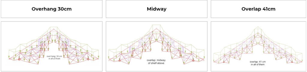
|| Deformation – Different Box Overlap Options
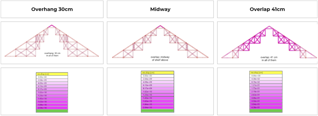
In terms of deformation, it is observed that the three structures behave similarly, regardless of having different distributions; all tend to deform under the considered distributed load. Therefore, we conclude that none of the structures is self-supporting or would be efficient on its own without relying on additional supports.
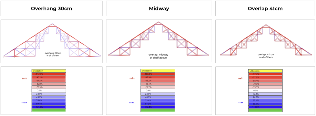
|| Global Utilization – Different Box Overlap Options
Through the analysis of the charts and tables, it is possible to observe that the 30cm overhang option, as well as the Midway option, are not suitable in terms of global utilization since both exceed the maximum limit of 100%. However, the 41cm overlap option fits the maximum allowed, with just some points that come close to the limit, reaching a maximum of 97.4% utilization in specific regions.
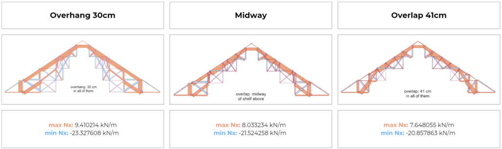
|| Axial Forces -Different Box Overlap Options
The structure with a 41cm overlap experiences the least amount of tension and compression when compared to others, which show higher values for both stresses. Regarding the path of forces along the structure, it is generally observed that the upper and external structures undergo compression, while the more internal structures experience tension.
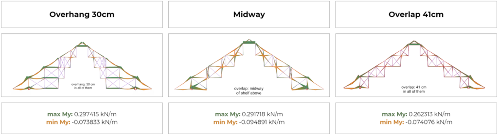
|| Bending -Different Box Overlap Options
In the structure with a 30cm overhang, significant moment values are observed in regions without lower support, unlike the structure with midway overlapping where the moment value is high where there is wall support. However, in the structure with a 41cm overlap, the highest moment value is located at the support, yet it is still lower than in all other options. This outcome is a result of a better load distribution.
|| Displacement – Different Box Overlap Options
2. Testing Connections Configurations
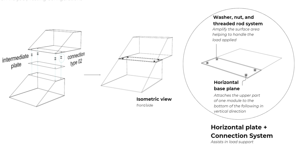
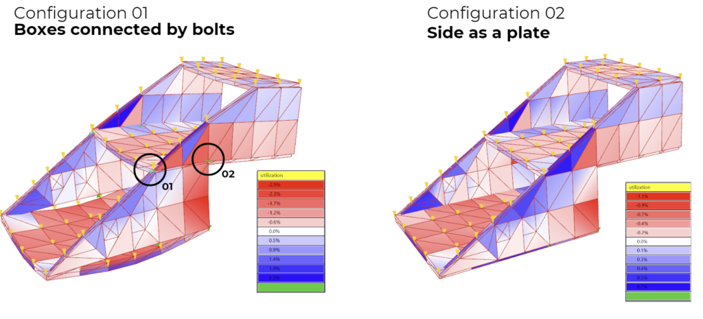
|| Configuration 01: Boxes + Horizontal Plate + Bolts
This structure features a planar intersection element between the boxes, anchored by a system of tensioned threaded rods, washers, and nuts. This connection binds the boxes, collectively operating as a load transfer system through their stacked distribution.
|| Configuration 02: Side Plates + Shelves + Bolts
**Entire lateral structures serving as guides and supports for the bottoms of each shelf.
This structure is secured by horizontal wooden slats, positioned beneath each shelf, which are screwed in both vertically and horizontally, creating a system for distributing forces among the elements.

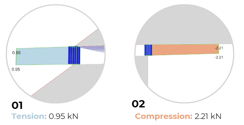
II Karamba Simulation of Configurations
The solid panel in the side of the structure is stronger and experiences less deformation compared to the option with bolts between the boxes. We extracted the maximum tension and compression values from the bolted connections, allowing us to make informed decisions on their proper utilization
3. Testing Connections Configurations + Supports
|| Qualitative Test – Shear vs. Bearing
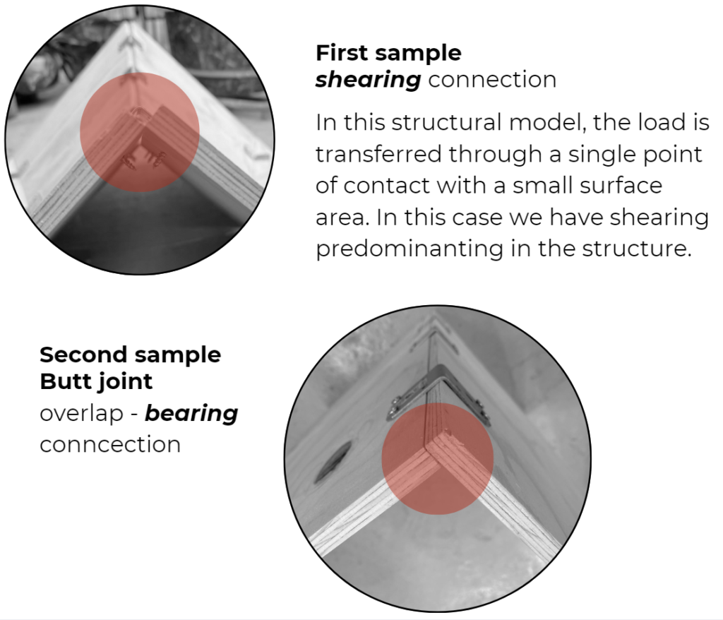
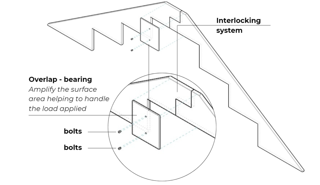
|| Resulting Design Evolution – Shear vs. Bearing
We observed that the second connection performed better and understood that overlapping and interlocking connections expand the contact area between elements. After confirming that this configuration would be beneficial for the system, we chose to incorporate the solution into the upper part, at the connection linking the structures on both sides of the roof. This way, the load can be transferred over a larger area, providing greater stability and resistance, thereby increasing its capacity to withstand forces.
|| Qualitative Test – Locked vs. Unlocked Geometry
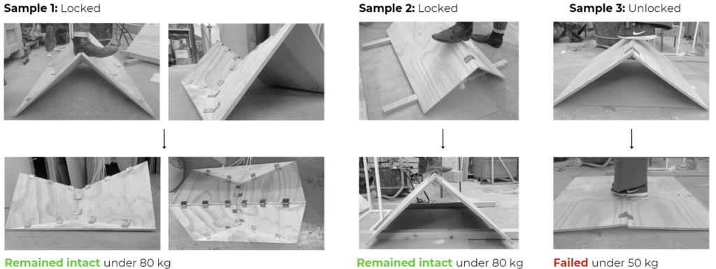
|| Resulting Design Evolution – Locked vs. Unlocked Geometry
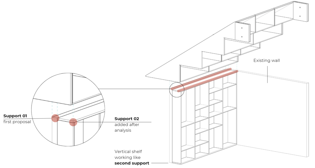
In opting for a fixed connection rather than a pin connection, we strategically improve the structure’s stability.The incorporation of shelves in front of the wall achieves a dual purpose: it mitigates forces acting on the elements and reduces the demands on connections.
III. Final Proposal – Hybrid Solution
|| Axonometric Section
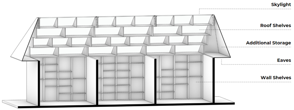
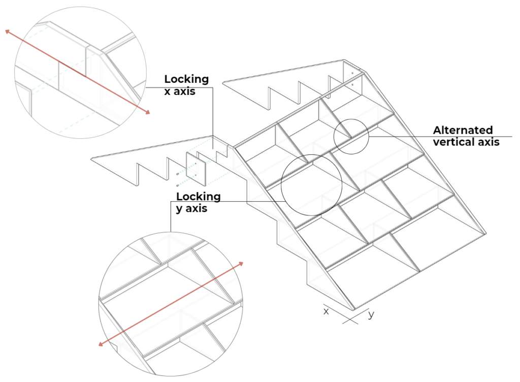
|| Structural Efficiency + Functionality
We implemented lateral planes to lock the structure along one axis, while stacked boxes with their bottoms serving as support along the other axis. However, we modified the boxes in such a way that we could prevent the vertical alignment of weak connection points between them.
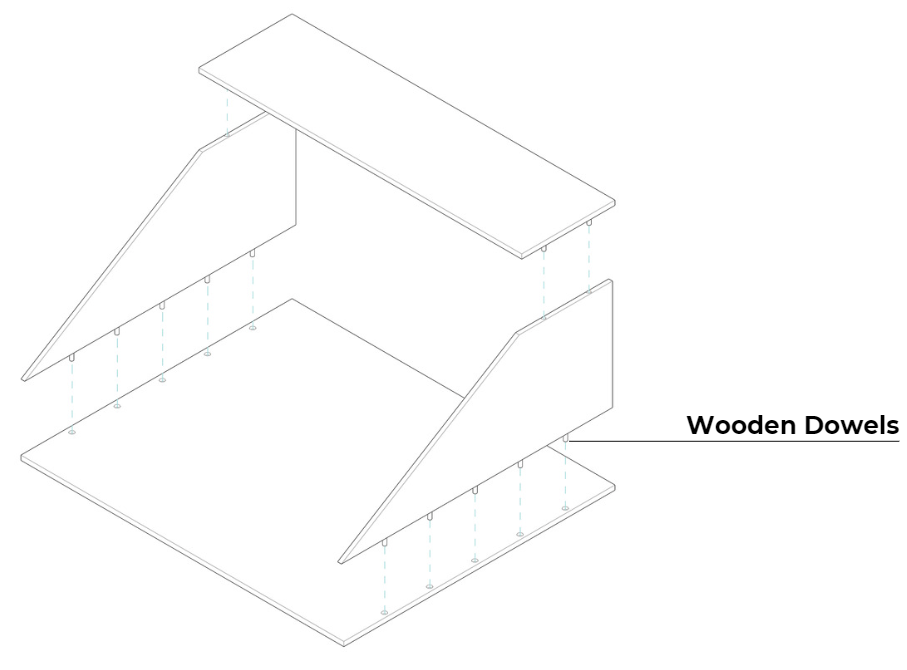
|| Box Stiffness
To further fortify our structure, we wanted to insure that the building block – our boxes – are structurally sound by increasing stiffness through the use of wooden dowels to hold the different sides of the box together while also maintaining its light weight.
Thank You!
