
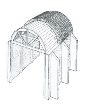
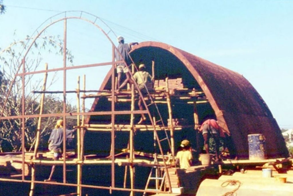
Support & scaffolding during consolidation of clay printing are quintessential to push the boundaries and capabilities of earthen architecture because, with said added support, opportunities for large spans, high arches, aggregated arches, and other structural phenomena arise. The options invented over time are diverse and, regardless of the used material, they can be very insightful when it comes to inventing molds and structures for arched earthen print. For example, the centring system used to carry arches were highly utilized over time and they acted as a catalyst to research inquiry.
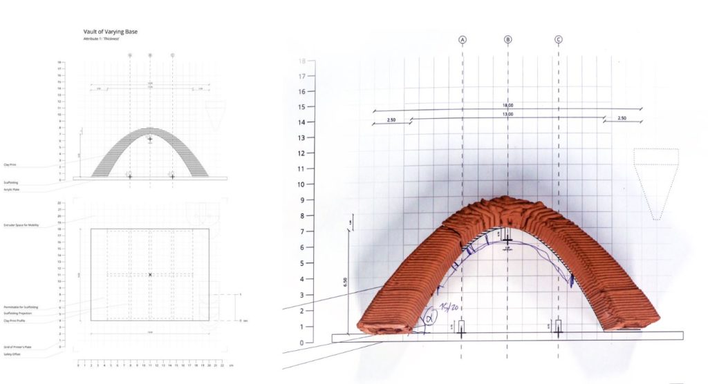
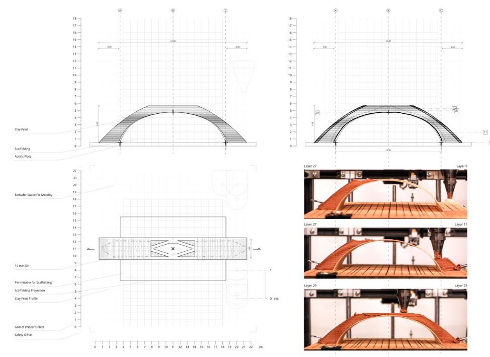
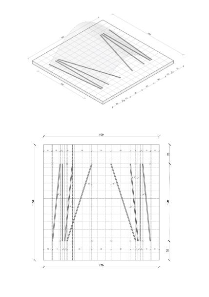
After assigning simple physical attributes to the arched clay prints to be printed, a safe formwork was developed to be placed in the desktop printer as a base for the arched print. This required a drawing setup that aids in drawing the route of the nozzle around the formwork. The formwork ratios of width to height ranged between 10:5, 10:4, 10:3, and 10:2.
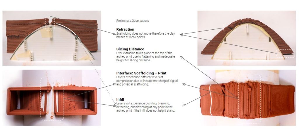
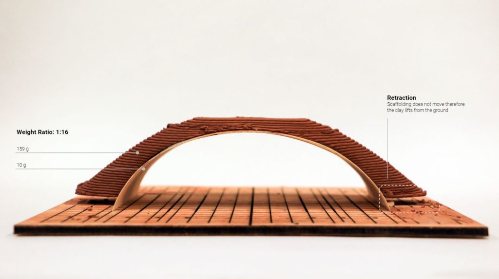
Preliminary observations were jotted down as research focus and they came up after the result of Cracking at weak points, over-extrusion, inadequate heights, compression due to inaccuracy of interface, and buckling. Reacting with refraction became a priority and this led to the research question. Since formworks are dry and cannot move naturally with arched clay prints which have natural movement during drying, the question at hand was:
How can active support systems control retraction during drying?
In Nubian techniques, a formwork in the form of a plane is used to define the outline of the arch construction and later removed. The strategy is to test materials that may be fruitful during the drying phase such as polypropylene and/ or wooden sheet. On the larger scale, for example, flex plywood could be used.
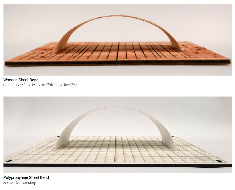
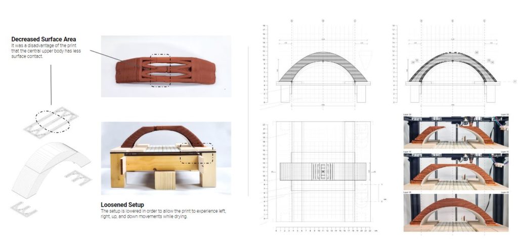
Wooden bendable sheets were craving quickly and the wetness of the print was dampening the thin wood which damaged its performance. Retraction was still observed which means the material was not moving enough during drying. One advantage which was good to carry in the experiment was the ratio of mass of clay to ratio of mass of formwork.
Polypropylene was a better choice because it allowed the desired movement. Up-down and right-left movement permits the clay print to relax on the scaffolding naturally and mitigate the cracks of retraction. A prototype was developed from scraps to understand the needed mechanisms in the physical.

After introducing a simple infill, several learning outcomes were harvested. They were jotted down on a manual that connects the strategy of the infill to the layer of the curve. Several rib infills were tested in order to achieve the most of the strategies in the manual.
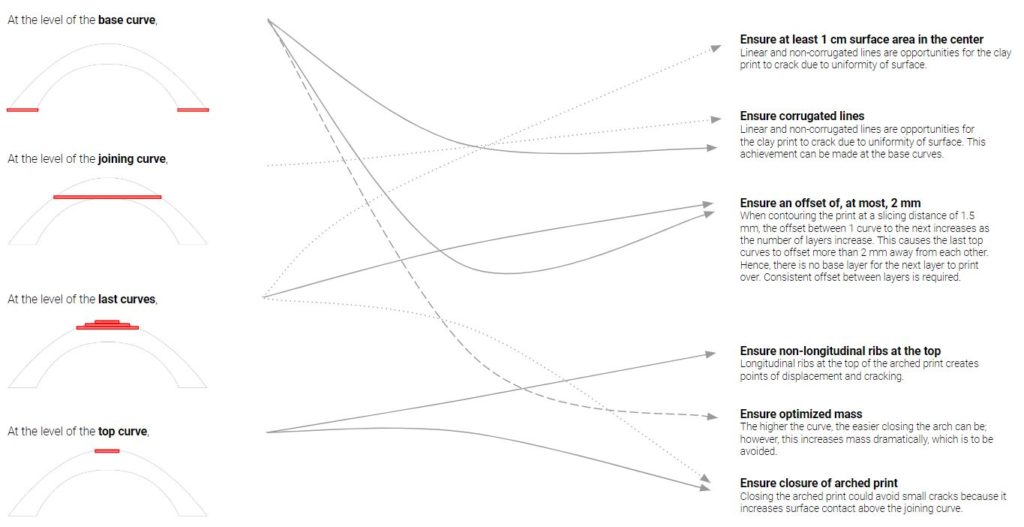
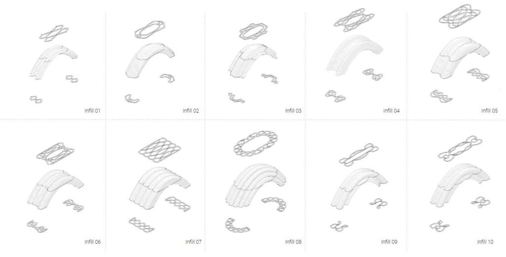
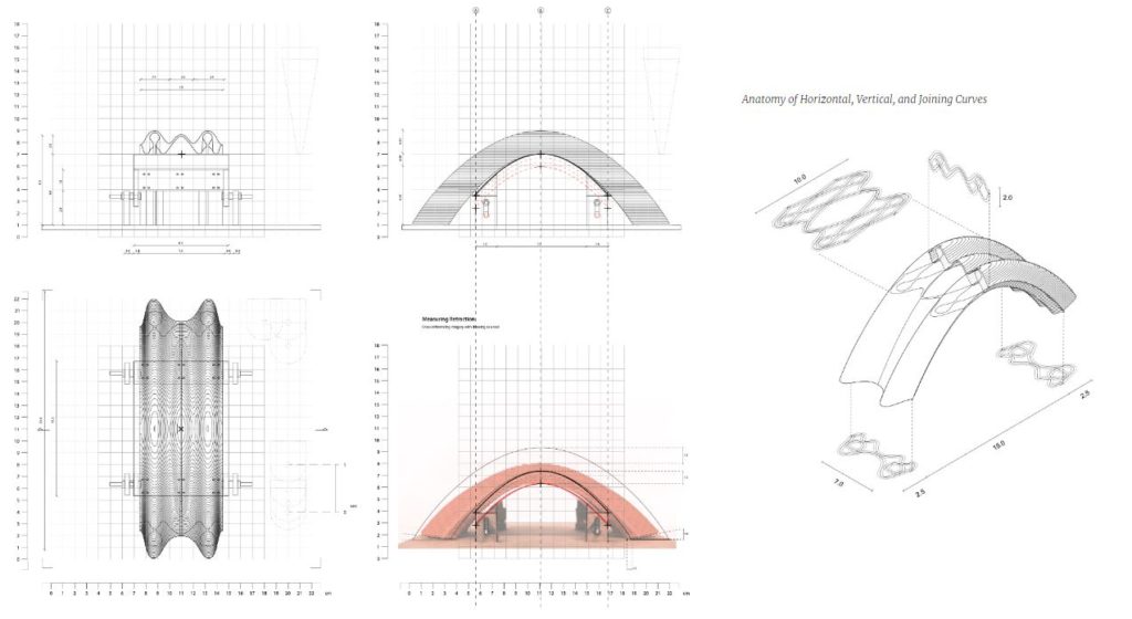
Two prints were the most synchronized with the strategies but they revealed insights regarding the slicing distance specifically in the last 10 layers. The objective was to close the top curve, rather than solely closing the bottom curve which is in contact with the scaffolding. However, the setup proved to be efficient since the shrinkage test showed that shrinkage was low. The shrinkage test was simply done by juxtaposing an image of a dry print against the digital drawing of the print when it is still wet.
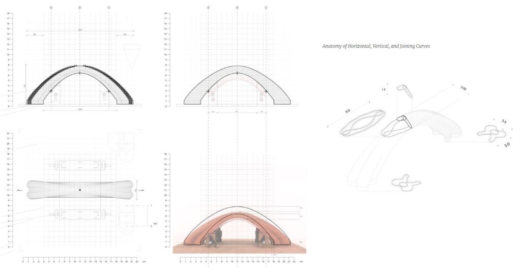
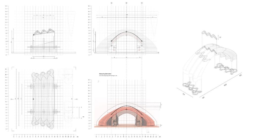
A digital analysis was conducted to add numerical understandings to the inconvenience of the last 10 layers. The slicing distance versus arch heights revealed that The higher the curve, the higher chances of the layers sitting on the preceding one. The lower the curve, the more the shift between layer position, and print becomes on the air. A physical print at several heights was conducted and the tests that had very useful outcomes were the ones conducted at the heights of 60 mm, 50 mm, and 40 mm. The scaffolding should carry points of weakness only and the angles with which the scaffolding should begin to support were extracted from these prints.

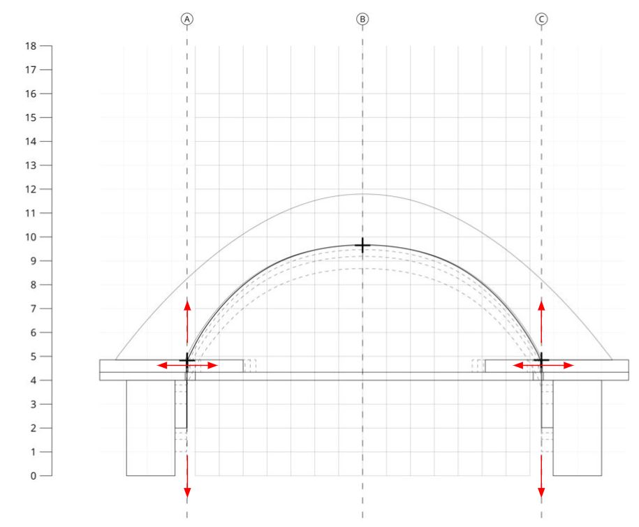
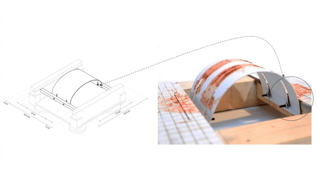
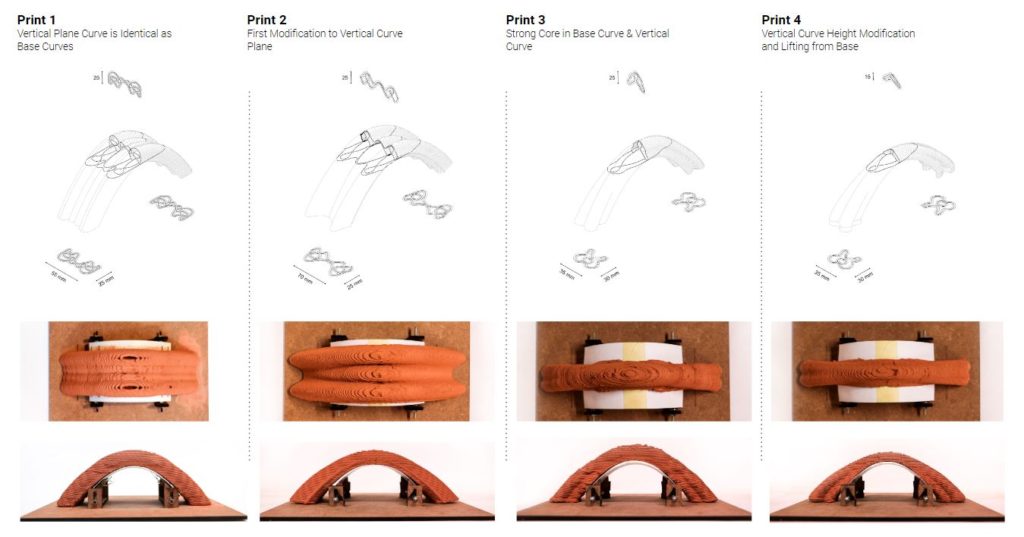
In order to optimize mass of the arched print and surface area of the parts of the print that has contact, the newest setup was used to print curves with a strategy that introduces a curve on the vertical place at the center of the print. This curve is swept with the two base curves. Each print experienced modification to the base curves based on the previously mentioned rib/ infill strategies; however, this time, there were consequential modifications to the vertical curve such as reduction of curve height and narrowing extensions. In the shrinkage tests, the eccentric movement setup proved to be allowing the natural movement that was desired.
The eccentric movement of the ball-socket joint system was the best way to understand the up-down and right-left movement that is natural and allows the arched print, which is represented by human skin that sits on the ball in this analogy, to slide naturally. The hypothesis was derived after the latest print being successful on many fronts.
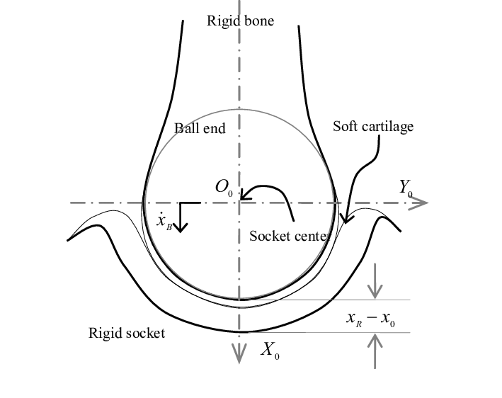
During drying, retraction of arched clay prints can be avoided by actively bending surface support that reacts with shrinkage.
Based on the tests, manual explorations were developed regarding different forms that could be generated by changing the direction of Slit in the plate, and Crosscutting the sheet surface for active bending. This produced forms that could be driven through the system of active bending. Based on the scaffolding system’s response to geometry, it was analyzed that this system works with a specific height vs width ratio. Threshold to support the eccentricity on the lower arch height Y-min and anything higher than Y-max ratio will not need a scaffold.


Opportunities from the digital workflow toolkit allowed many options for scaffolding and consequential print. A system was set up to evaluate the curvature of the surface and generate supports at the points where floor brackets would have sufficient span to move and the angle of curvature, thus reducing the surface area of the bended sheet. Also, based on the length of the geometry, floating surface wooden brackets were added.

The new scaffolding was one that is slanted because it accommodates the lowest permitted arch height sweeped with the highest.
The final print challenges the ribs, infill, scaffolding, inclinations, and other parameters to achieve an aggregate. The usage of scaffolding in this print was to introduce an examination of scaffolding position in large prints for future prospects.
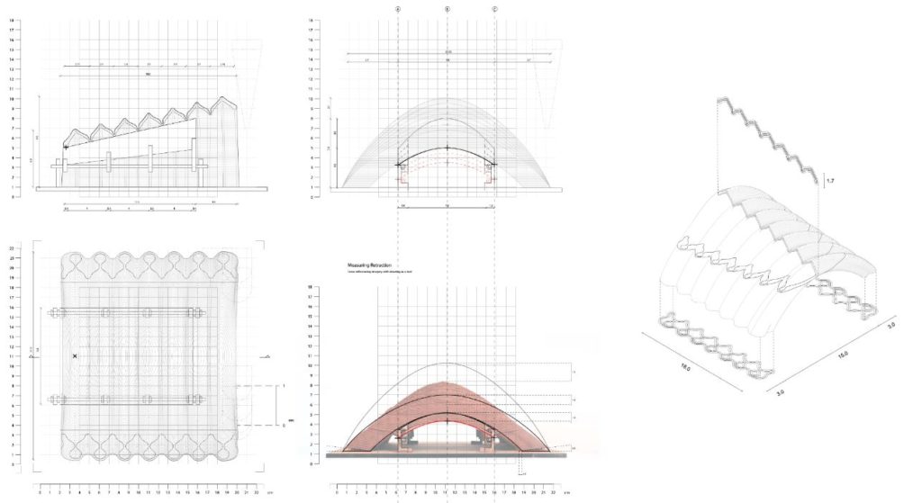
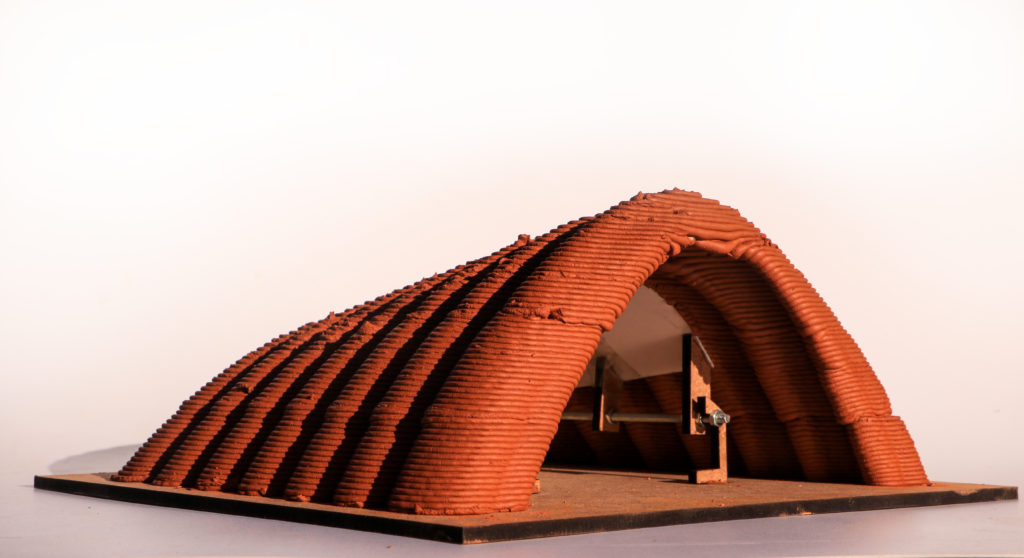
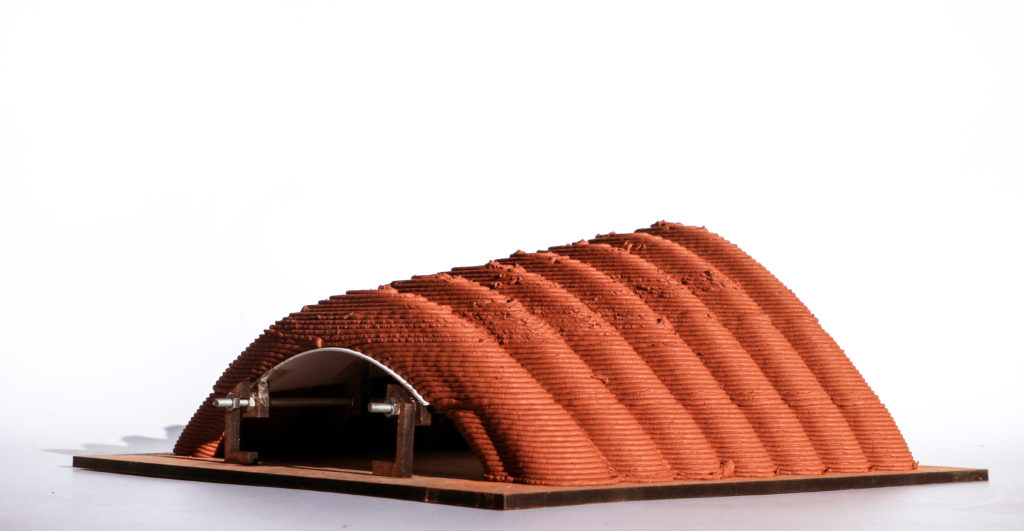
There was a resulting symbiosis between the set up and the print. In sum, The workflow starts with surface geometry generation with response to the parameters. The infill is generated to produce the geometry, parallel to generating the scaffolding to support eccentric movements. As the geometry is printed on a scaffold, the tool path has been optimized to prevent collision on the scaffold setup. Finally while drying the scaffold shall move in response to retraction.

