Project Brief
Solis Centrum is a project for the BIMSC Studio class within the 2023/24 MaCAD program. This project aims to represent the solar center of the Aleph City community, a conceptual community on Mars located on the Valles Marines.
Mission Statement
Solis Centrum aims to represent the solar center of the Aleph City community. By providing residential, recreational, and energy harvesting facilities, Solis Centrum can not only provide places for occupants to live and work toward our goal of providing power to Aleph, but also provide opportunities for inhabitants to enjoy and make the most of their time within Aleph. By using an elevational approach, Solis Centrum rests atop the mountain overlooking the Valles Marines. Using a folding construction method and inflatable habitat interiors, two sizes of units are easily aggregated along the hillside and then partially covered by a series of protective shells to block out radiation. Outside of the shells are a series of solar collection units to power Solis Centrum and Aleph City.
Programming

By providing residential, recreational, and energy harvesting facilities, Solis Centrum can not only provide places for occupants to live and work toward our goal of providing power to Aleph, but also provide opportunities for inhabitants to enjoy and make the most of their time within Aleph.
Location
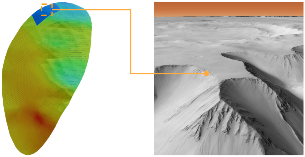
Solis Centrum is located along the northern mountain top of the Aleph City Macro Site. This location allows for maximized view of the valley below, as well as maximized solar gain for the energy harvesting process.
Design Approach
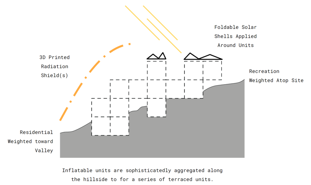
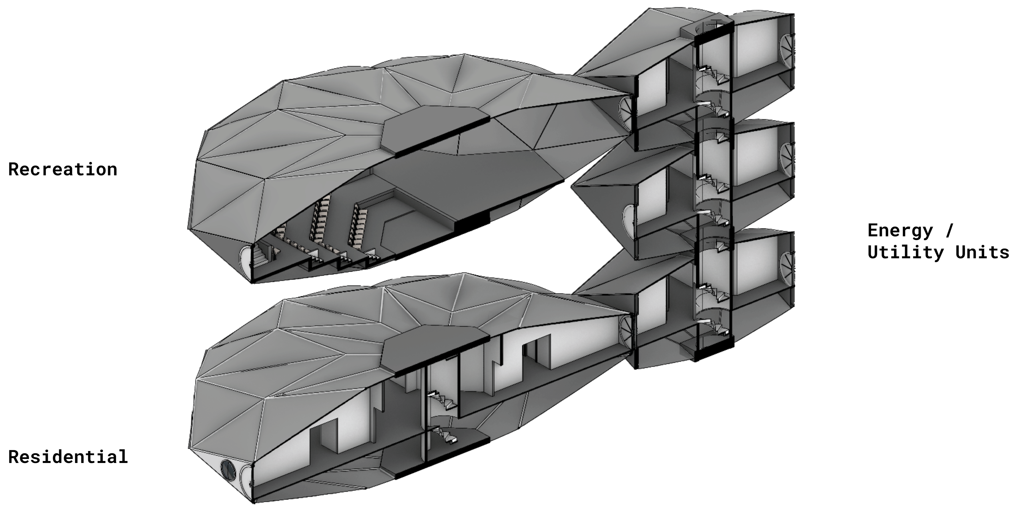
The design process for Solis Centrum is represented by the Parti Diagram shown above. Following an elevational approach, Solis Centrum is comprised of repeatable modules that have recreational units weighted toward the top of the site, while residential is down below. Connection units are populated between recreation and residential spaces with foldable solar collection modules placed in surrounding areas. Finally, a regolith shell is placed over a cluster of units for protection from radiation.
Precedents
Hassel
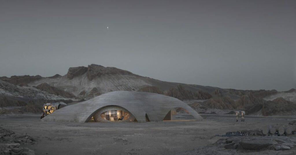
The first precedent for Solis Centrum is The Mars Habitat from Hassell architecture group. This project utilizes inflatable modules as well as a 3D printed shell for protection from radiation on Mars.
Nasa
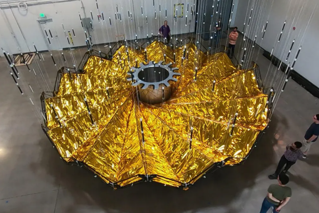
The next precedent is the Starshade from Nasa and JPL. This design makes use of foldable mechanisms to ensure for compact design during space travel.
Computational Design Process
In order to ensure a data driven approach, Solis Centrum’s design is the outcome of a specifically crafted design process.
Circle Packing into Meta-Balls
The first step in this process utilized the method of ‘Circle Packing’ to determine the most compact space for the chosen programs. By assigning priorities weights to the three program options ( Residential – 33%, Recreation – 47%, Energy – 20% ), a grasshopper definition was able to produce this compact site while maintaining necessary program space.
Next, these packed circles are converted into Meta-balls, and then wrapped to get a joined surface. This surface represents the boundary of the Solis Centrum intervention site.
Aggregation Field Creation
Once the boundary is defined, within Grasshopper, the plug-in Wasp is used to create two separate fields to dictate aggregation. The first field created, ensures that aggregated modules remain close to the surface of the boundary site and are not completely floating or buried.
The second field creates a path for the aggregation to follow. This field guarantees modules are not completely random and stay within the boundary location.
Parts and Connections for Aggregation
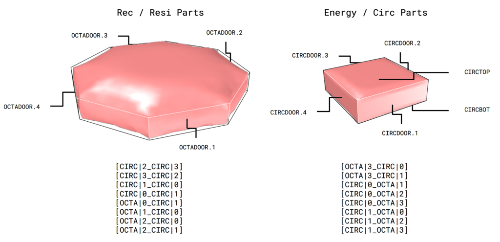
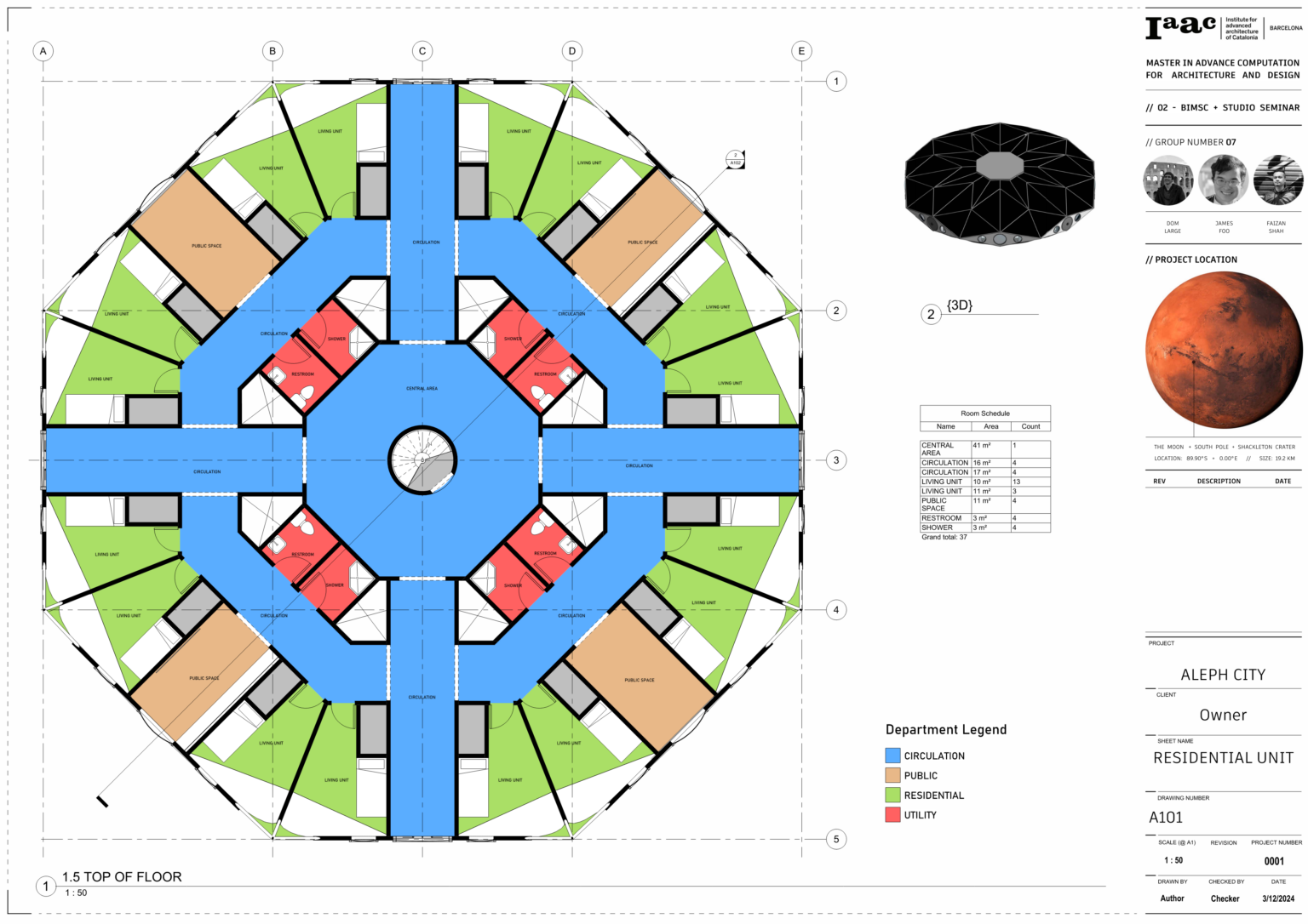
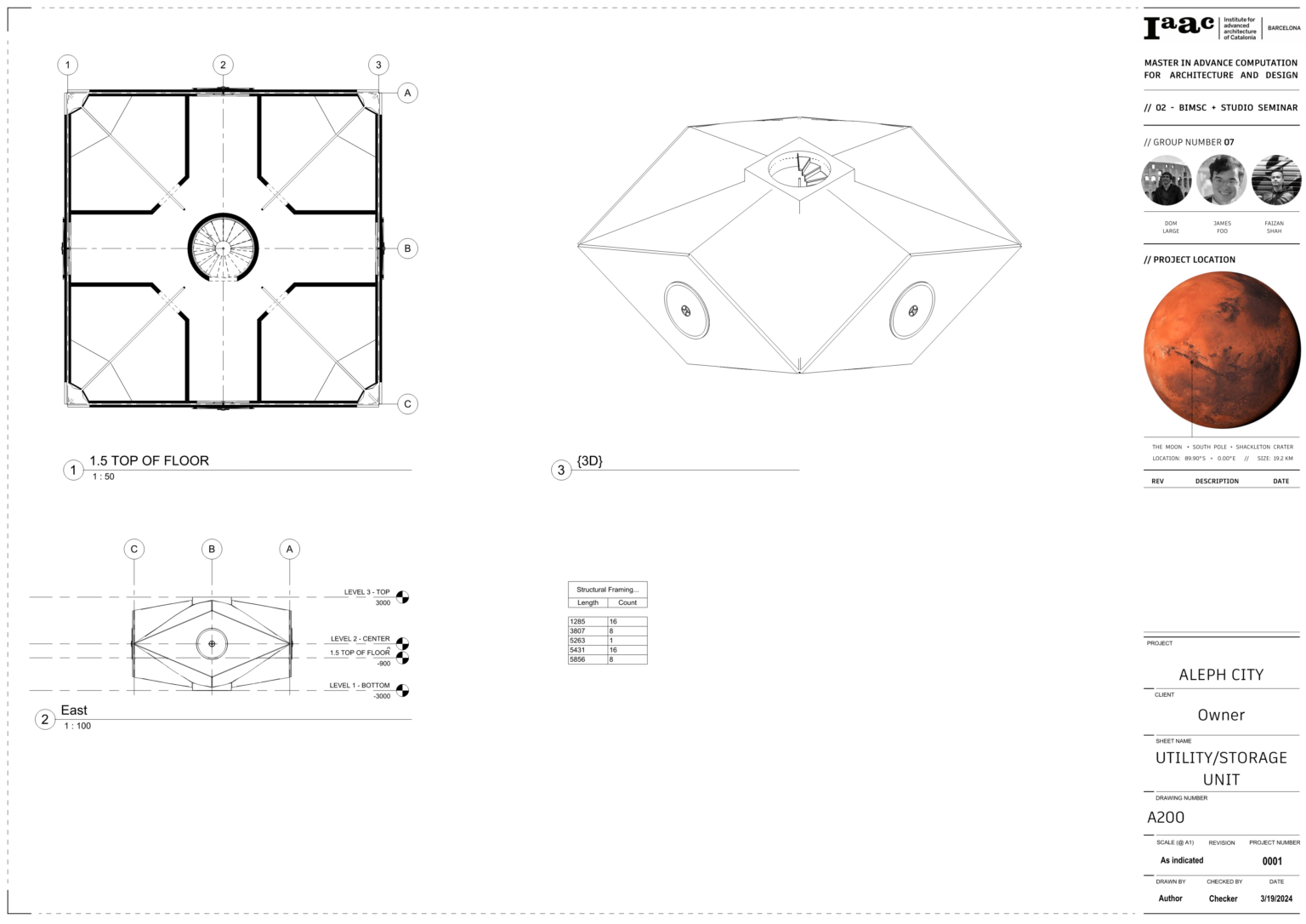
Now that fields are created, the modules and their connections are created for aggregation. The first module, the larger part, represents units that will be used for either recreational or residential programming. The smaller module, will be used both as circulation space and energy storage.
Both of these modules are given specific connection points with corresponding connection rules. These rules dictate how the modules will connect with one another to form a deliberate cluster without overlaps or collisions.
Wasp Aggregation
After the fields and modules are created, they can both be used as inputs to create ‘random’ clusters of aggregated units. Once these modules are in a cluster, the larger modules are divided into two groups, residential and recreational, to calculate the maximum amount of inhabitants it can support. Finally, regolith support is relocated to provide support for any modules that may need it.
Radiation Shield Placement
Once an aggregated clustered is successfully created, a regolith is created to provide radiation protection while still allowing for sunlight. First, Kangaroo within Grasshopper is used to drape a mesh over the cluster. This drapes mesh is then trimmed in specific location informed by the aggregation, to allow for sunlight to enter underneath and provide views from specific modules. Finally, this shell is supported by a series of columns with locations dictated by structural weak points and aggregation clusters.
Solar Module Placement
Lastly, solar panel modules are placed surrounding the cluster and shell. Collision tests are run along the way to remove and modules placed where they may interfere with constructed modules or regolith.
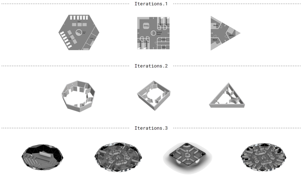
Aggregation Iterations
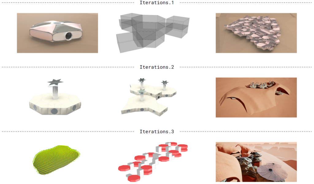
Interior Iterations
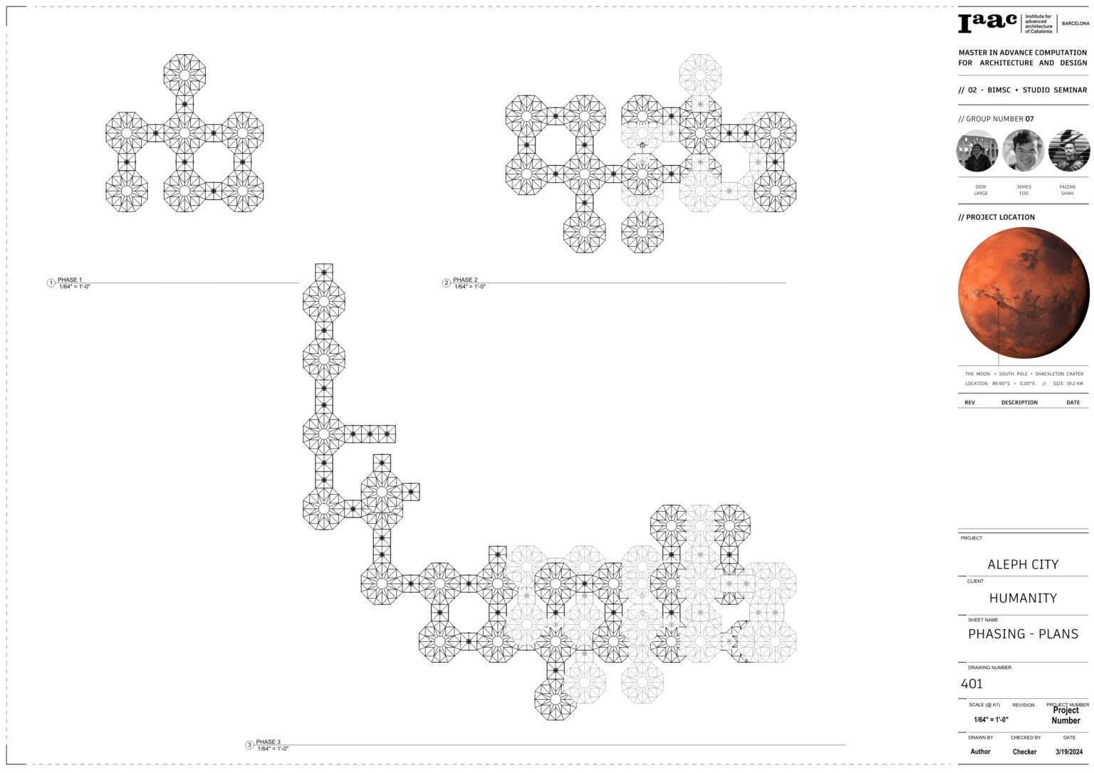
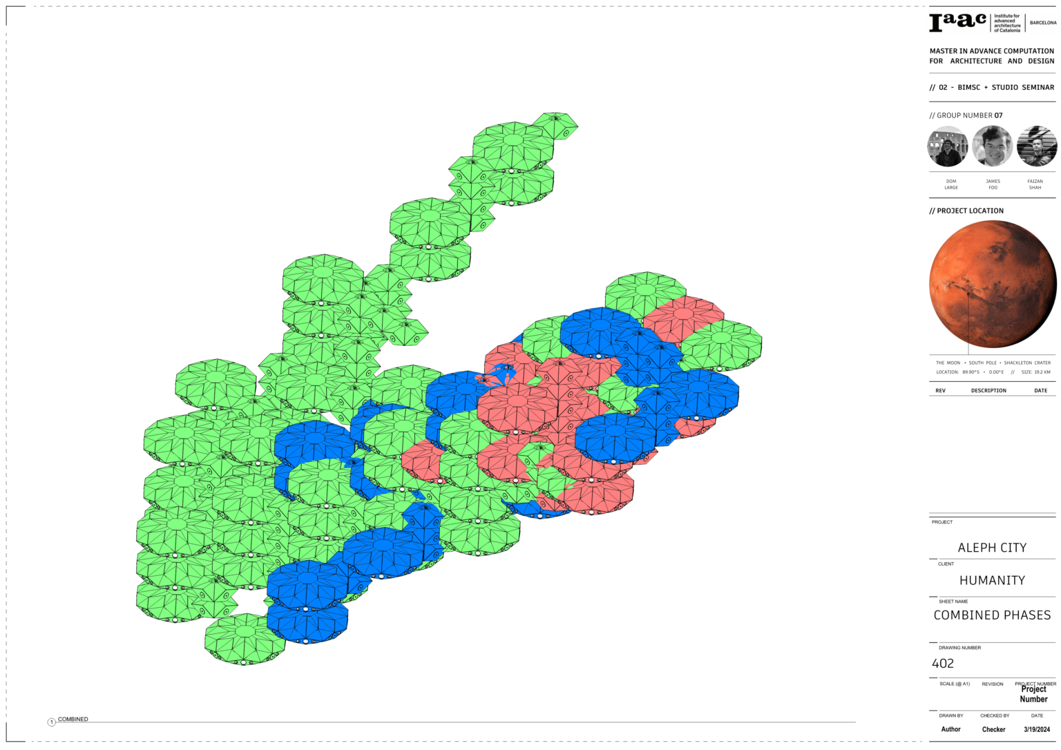
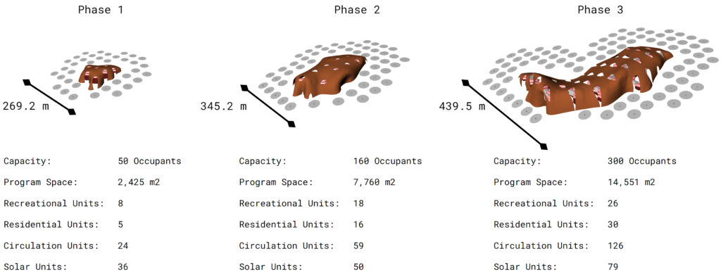
Colony Phasing Scale
Modular Aggregation Units
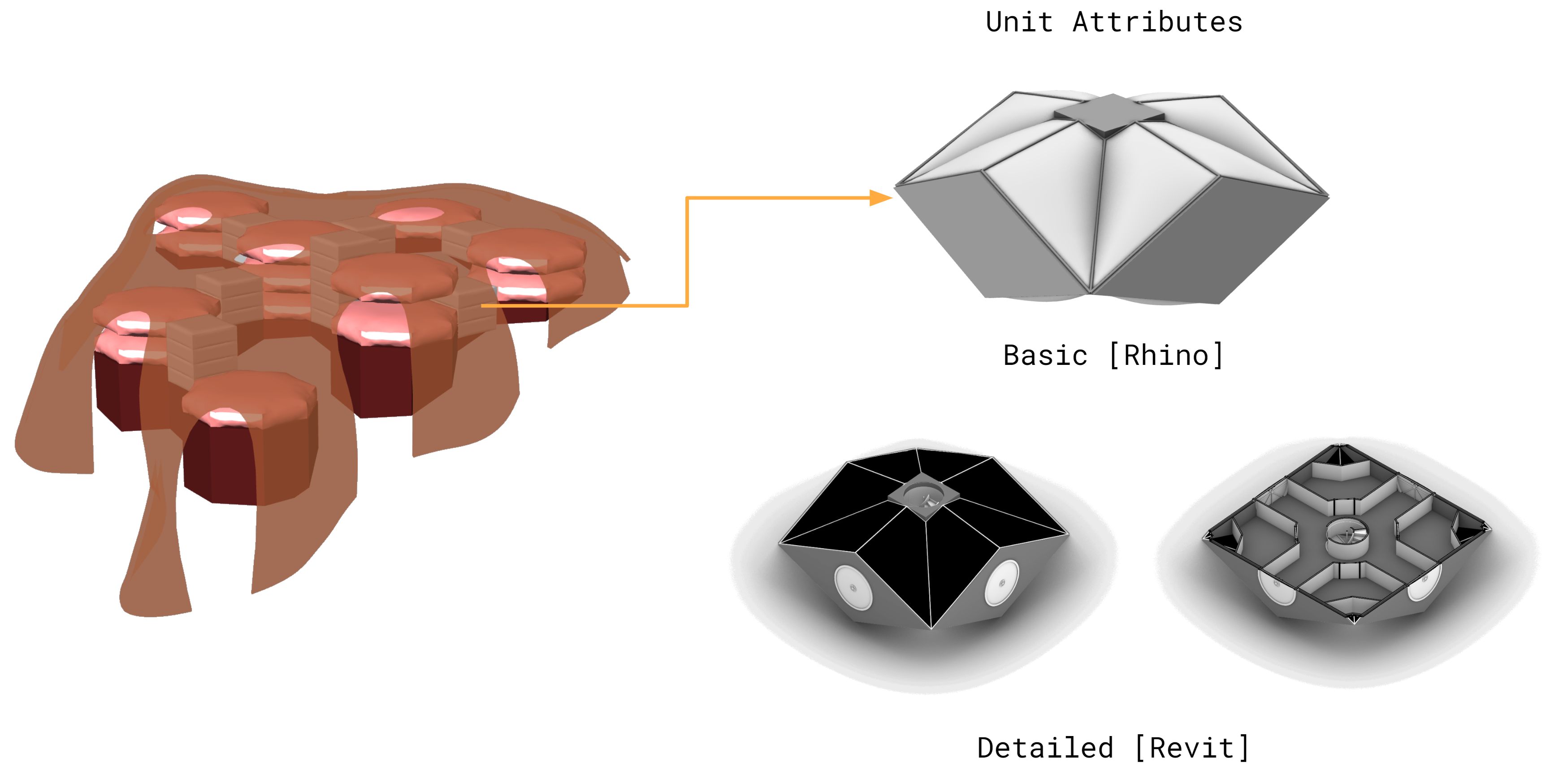
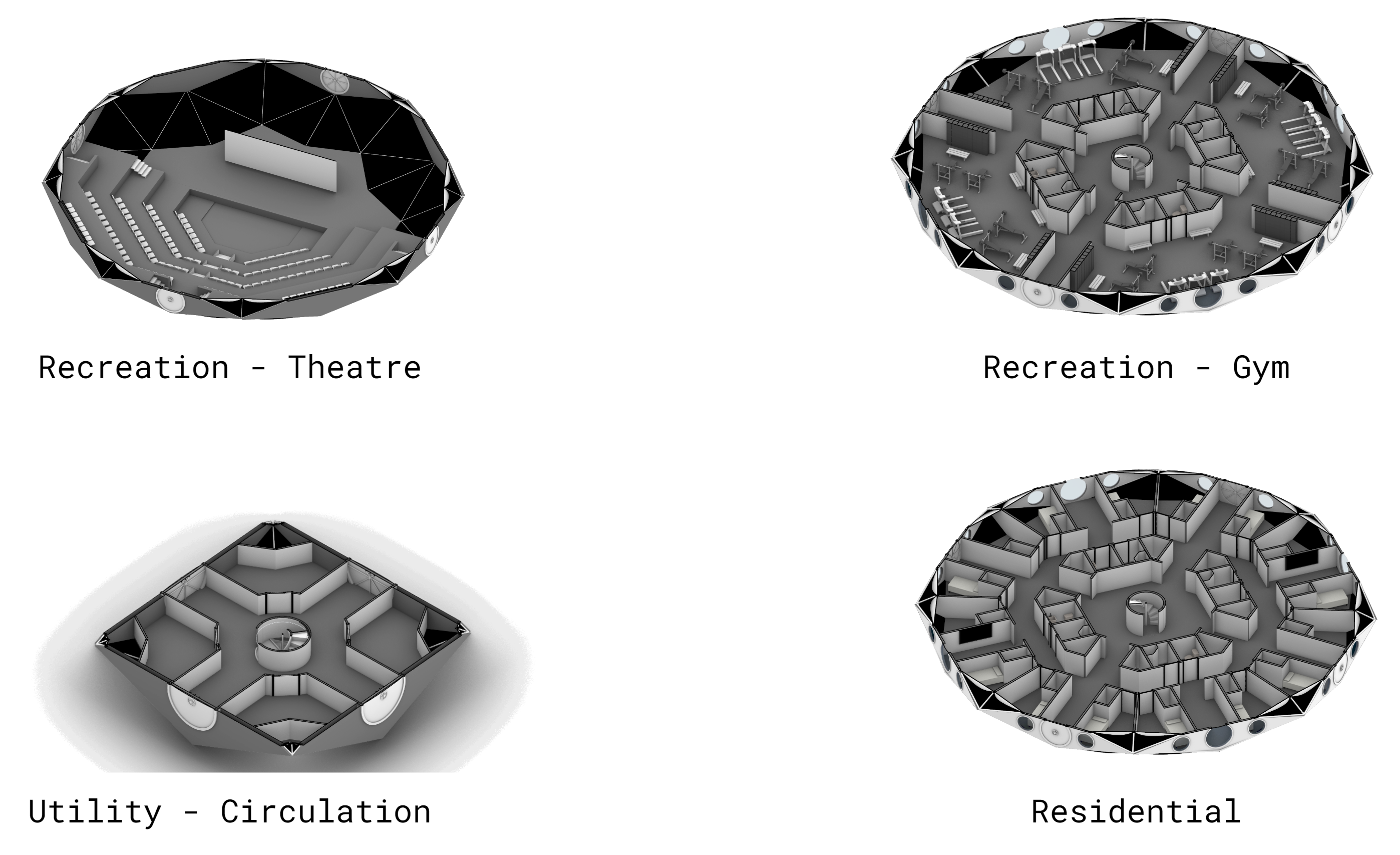
Residential and Recreational Modules
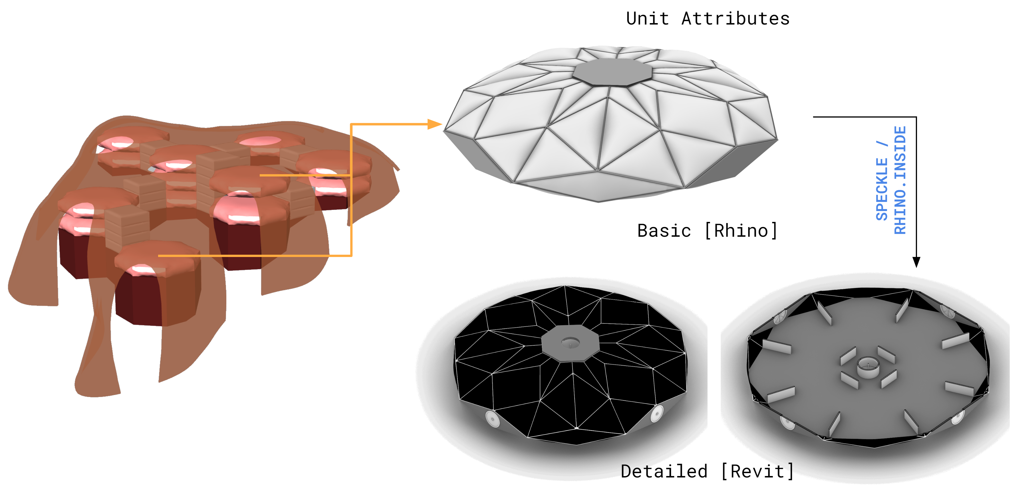
Modules are given basic attributes within Rhino before they are transferred to Revit via Speckle for detailed modeling.
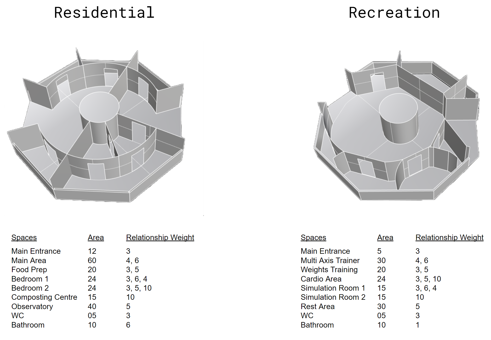
To determine interior layouts, a spatial syntax was used to generate activity location and space by specifying different needs and their priorities.
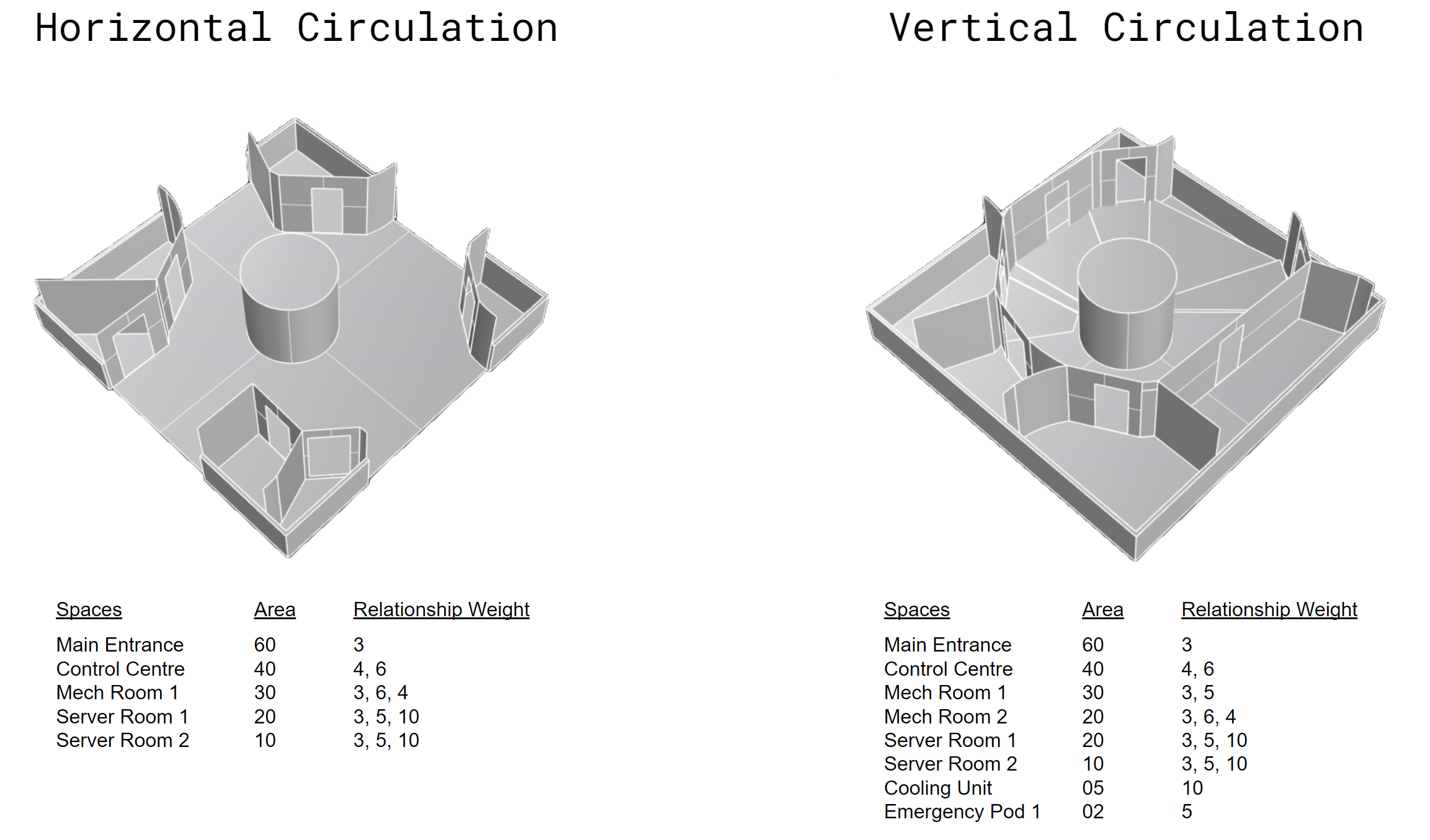
Energy Storage and Circulation Modules
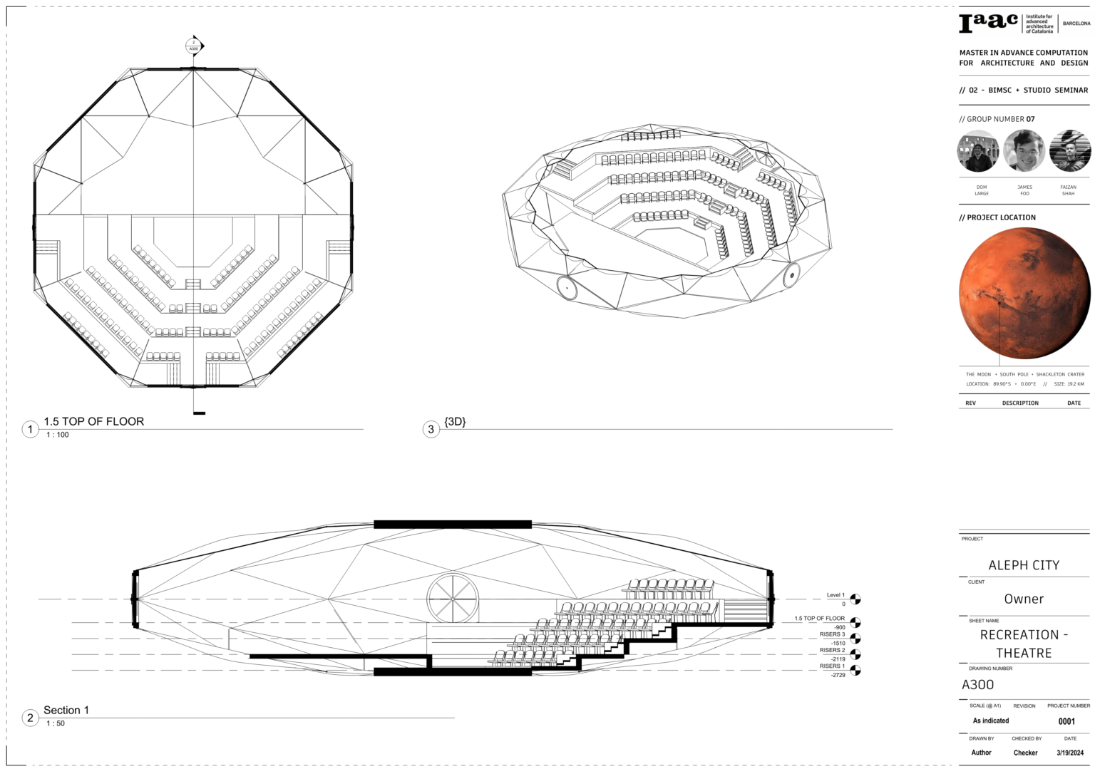
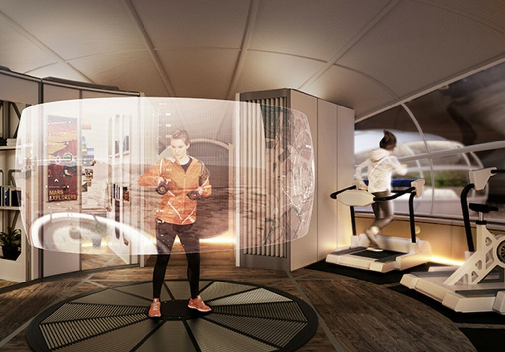
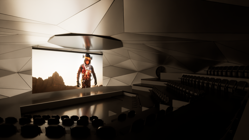
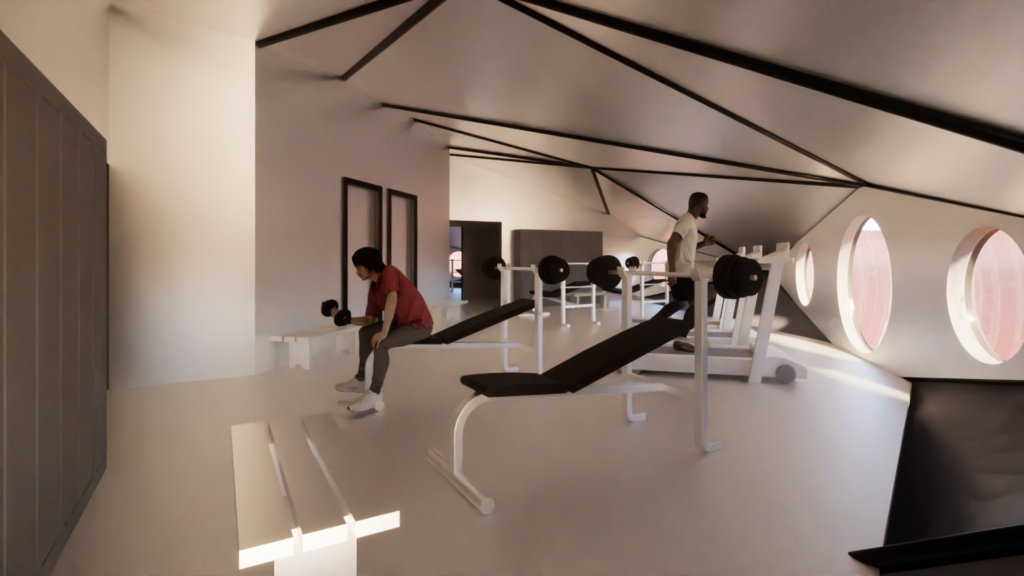
Martian Recreation
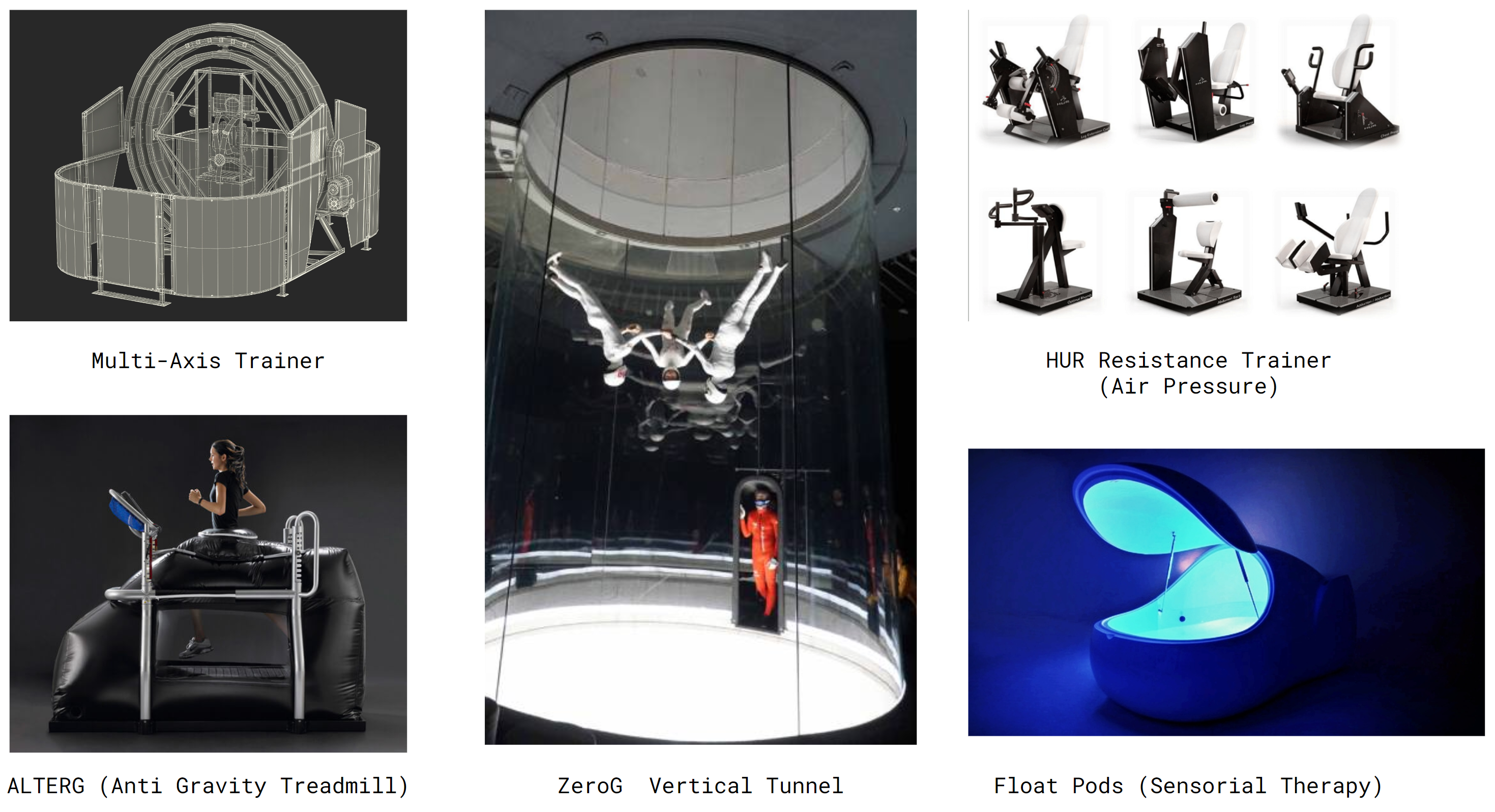
Some of the specific recreational activities that were chosen are shown above. These activities were chosen based on the gravitational and atmospheric limitations of Mars.
Materials and Construction
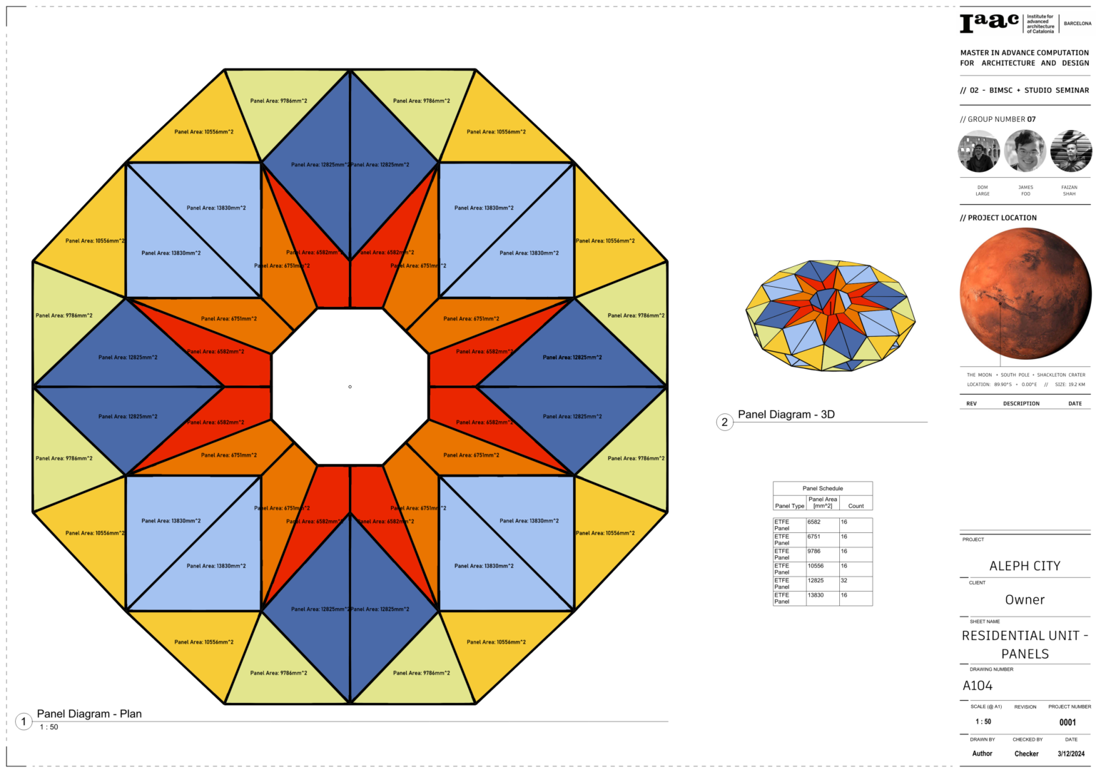
Module Materiality
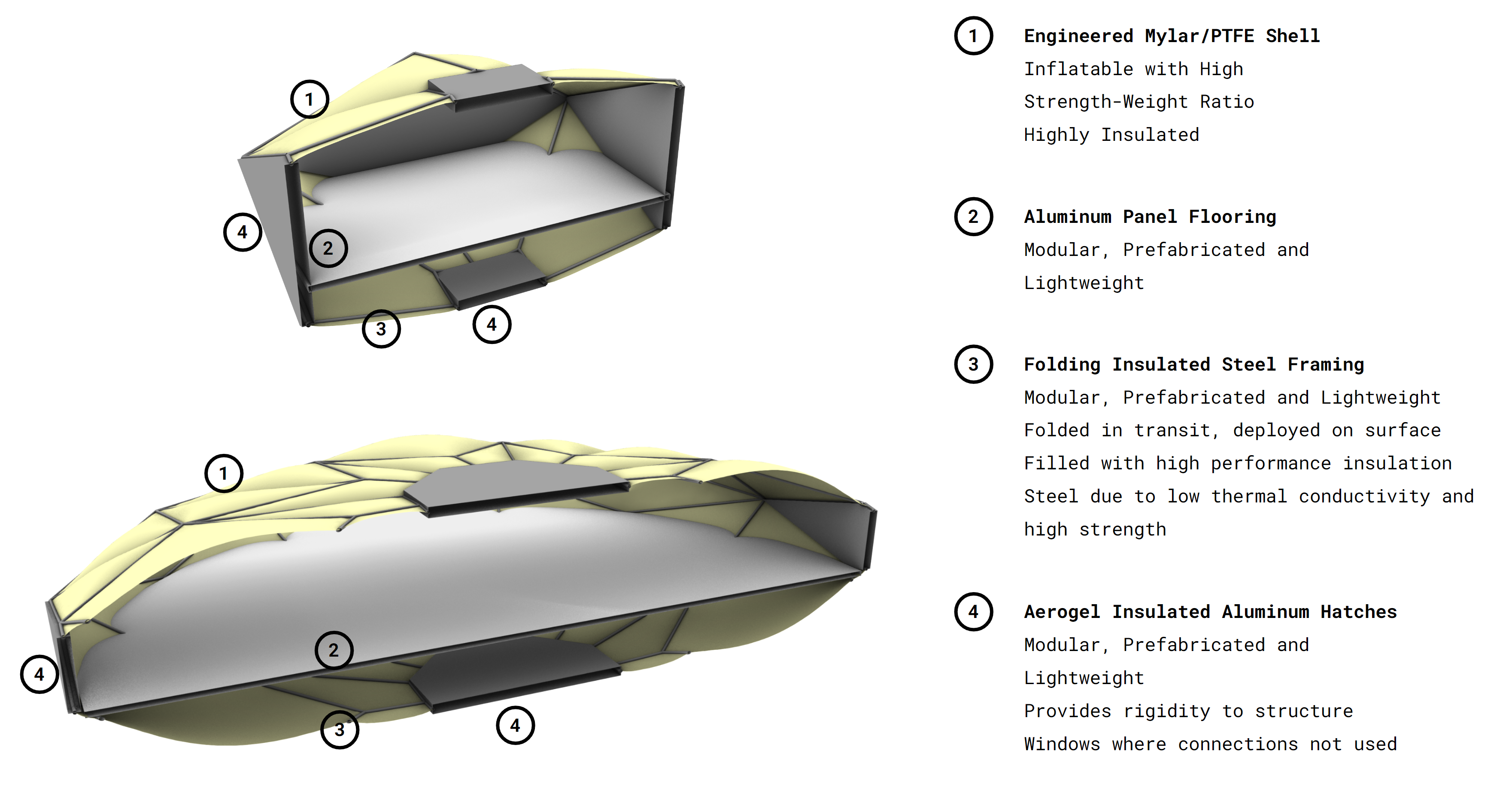
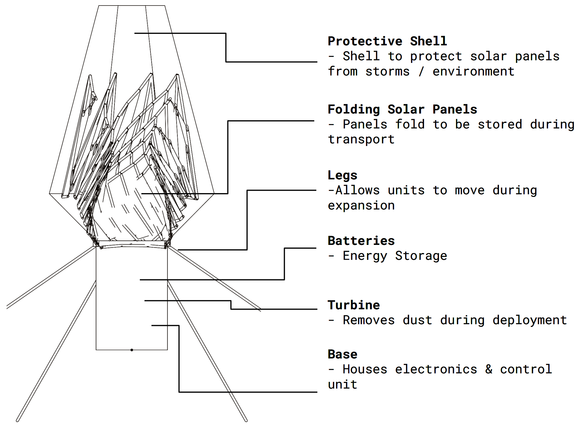
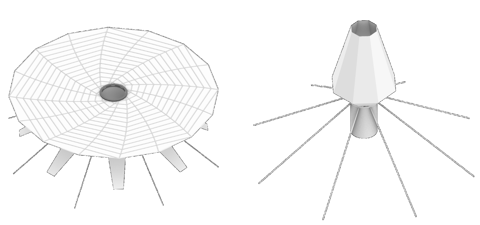
Solar Module Materiality
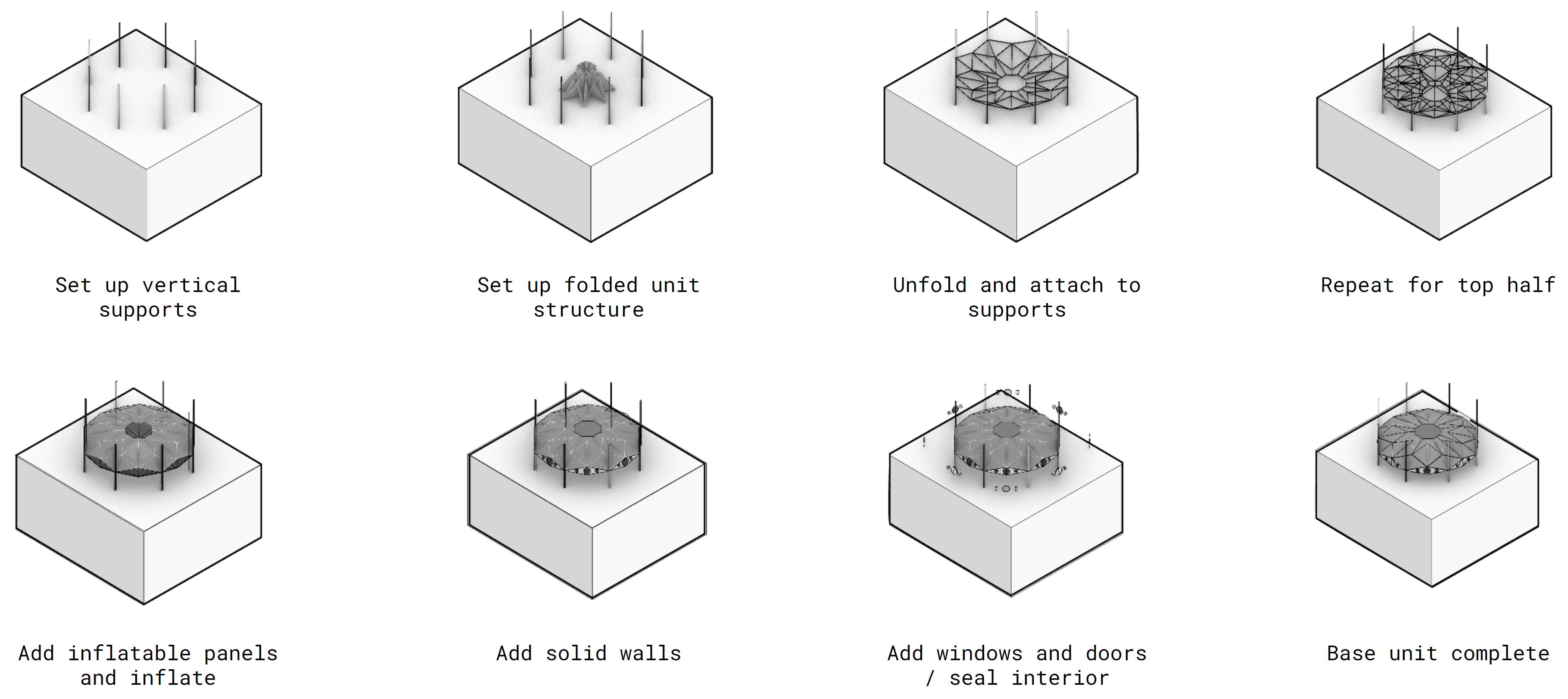
Module Construction
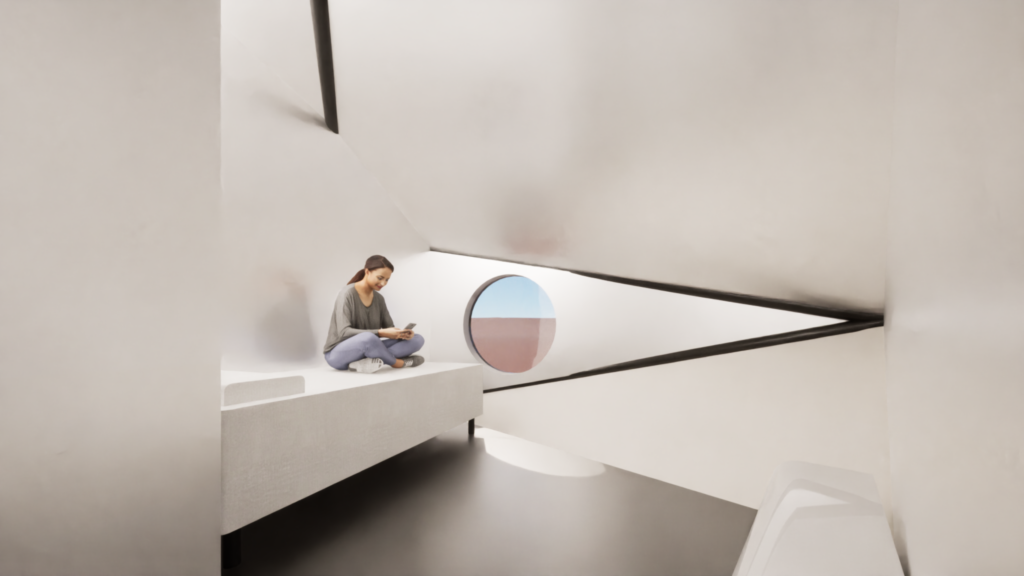
Specialized Module Interiors
Module Cluster
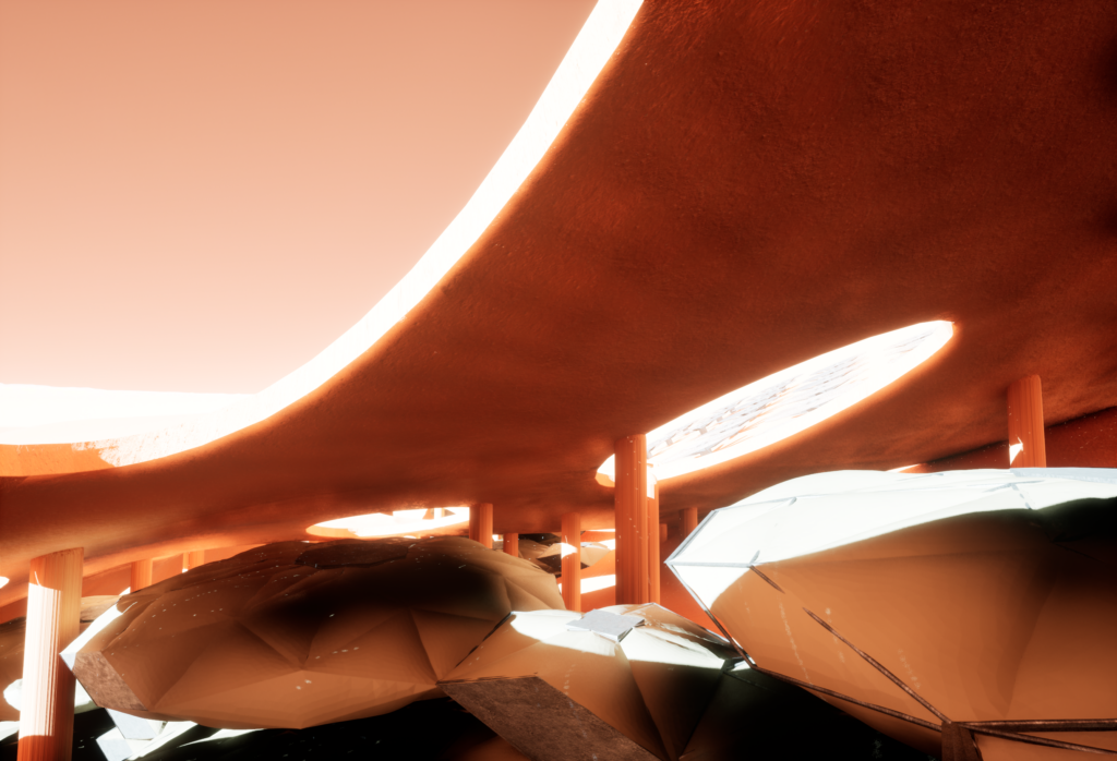
Concept Renders
Unreal Engine 5
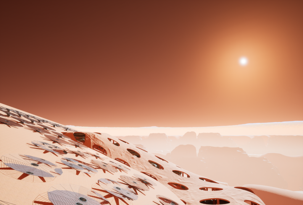
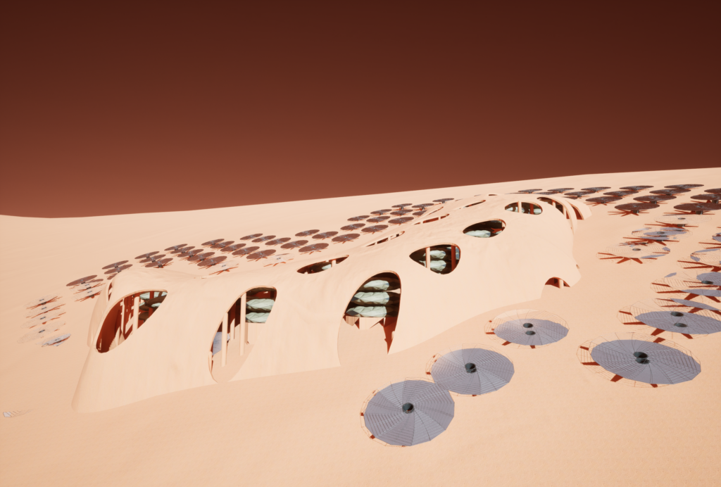
Twin Motion
Collaborative Workflow
Speckle was the primary vessel of information between the designers. Each designer took on a different scale of the project, with Dom focusing on the large-scale overall aggregation and site, James focusing on the medium-scale unit geometry, and Faizan dealing with the small-scale interior layouts. Speckle’s ability to manage and curate data structures were vital in our pipeline of information from Rhino to Revit.
Automation
Rhino-to-Speckle-to-Revit
Shown above is the grasshopper definition responsible for the creating the unit geometry. After the script is run, the final data is packaged in a highly specific way to facilitate its use in Rhino.inside.
This definition shows the process of the packaged data being deconstructed and used to create the native Revit geometry.
Geometry Placement
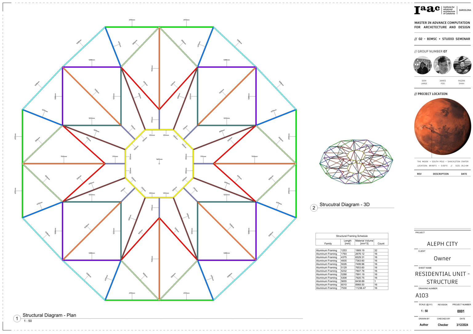
The grasshopper definition shown above was created to automate the process of placing geometry that represent mechanical and structural elements. Because these elements were designed to be modular, the automation process was simple to create, yet effective in saving large amounts of time completing this task that would typically be done by a group member for each module in the design.
BIM Documentation