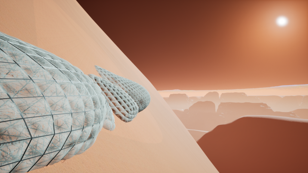
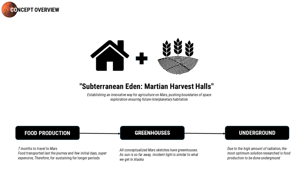
“An innovative way for agriculture on Mars, pushing boundaries of space exploration ensuring future interplanetary habitation.”
Mars—the Red Planet—is getting closer. According to the experts, human settlements on Mars might be visible in ten years, allowing for more space exploration. Keeping that in mind, this semester’s goal is to create a 300-person Mars colony.
The Subterranean Eden: Martain Harvest Halls focuses on creating a food production colony for Martians, complete with housing. Our primary goal is to develop a novel approach to agriculture on Mars while pushing the envelope of space exploration and guaranteeing interplanetary habitation in the future..
SITE AND TOPOGRAPHY
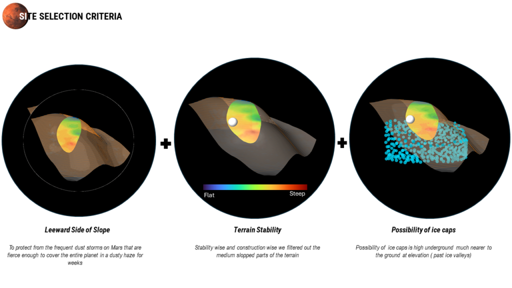
The project is situated within Valles Marineris, a network of canyons on Mars that stretches along the Martian surface to the east of the Tharsis region. It holds the distinction of being the largest canyon in the Solar System. Within this expansive region, we were allocated a micro site spanning 10km by 10km were we carefully choose the site for our project, guided by three primary criteria.
- We prioritized selecting a site on the leeward side of the mountain to provide shelter from the intense dust storms common on Mars. Consequently, we excluded flat and gently sloping areas displaying colors ranging from blue to green.
- For stability and ease of construction, we also excluded the highly steep sections of the terrain
- Additionally, we considered the likelihood of locating a water source, noting that the probability of finding one at the cliff’s edge may be higher than at the lower parts of the mountain.
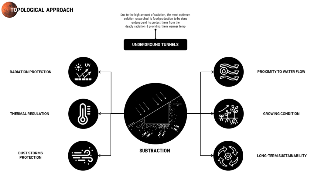
Topological Approach
Our project’s topological strategy revolves around subtraction, particularly through the implementation of underground tunnels. We have opted for this approach for several reasons, including shielding from radiation and mitigating the effects of extreme surface temperature fluctuations. Underground spaces offer a more stable and moderate temperature environment, enhancing overall protection and sustainability.
DESIGN CONCEPT
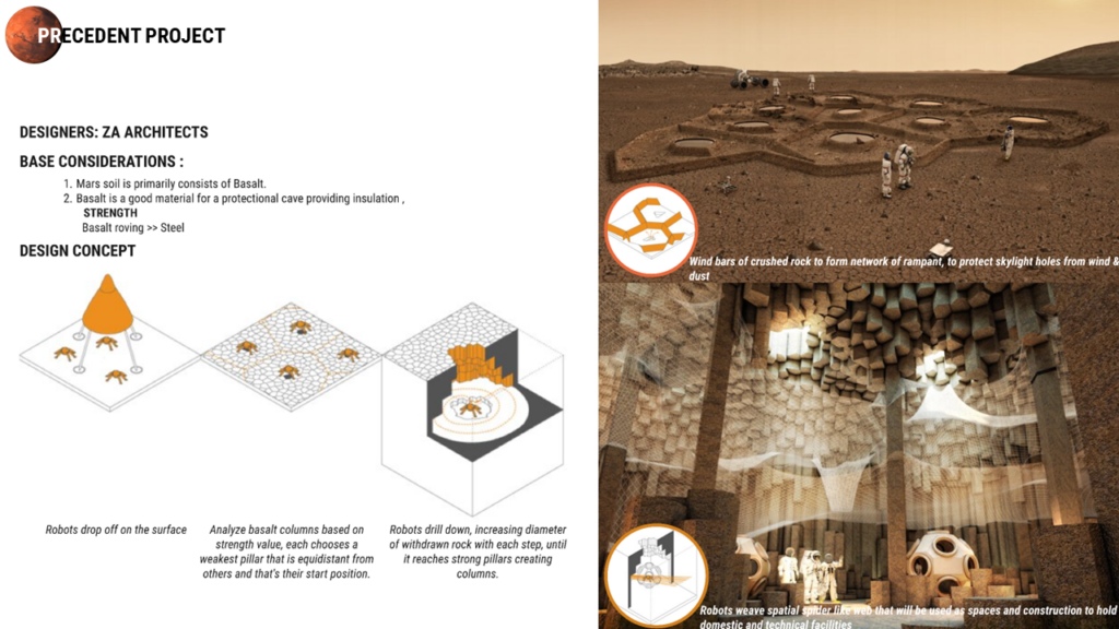
The design concept is inspired from the precedent project of ZA Architects for Mars Competition.
Mars soil primarily consists of Basalt which has good insulation and its roving is also stronger than steel. Their design concept was that once the robots are dropped on the surface they analyze basalt columns based on the strength value each chose the weakest pillar and start drilling down with increasing diameter at each step to create strong pillars.
CONCEPT
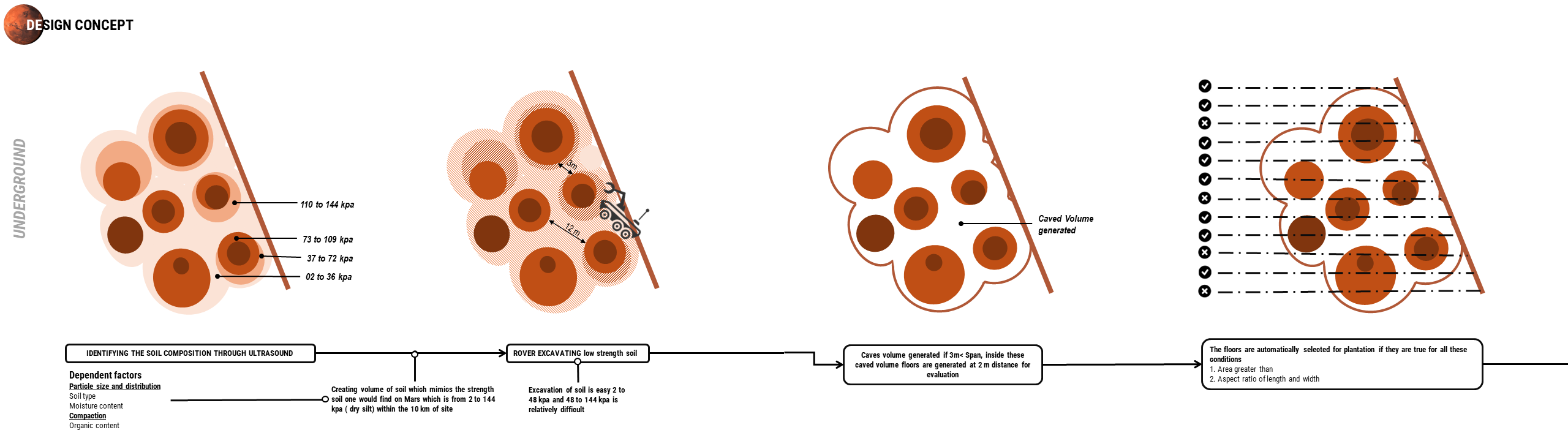
For the design process we started with mimicking the Martian soil, the composition of any soil is based on particle size and their compaction level along with moisture and organic content. As martian soil lacks both the soil strength is replicated from the first factors.
The Martian soil has strength from 2 to 144 kpa , in which the rovers can easily excavate the soil with strength from 2 to 48 kpa focusing on areas with a minimum span of 3m.
Inside these excavated volumes, floors are generated at every 2 m and then selected based on minimum areas and their aspect ratio criteria
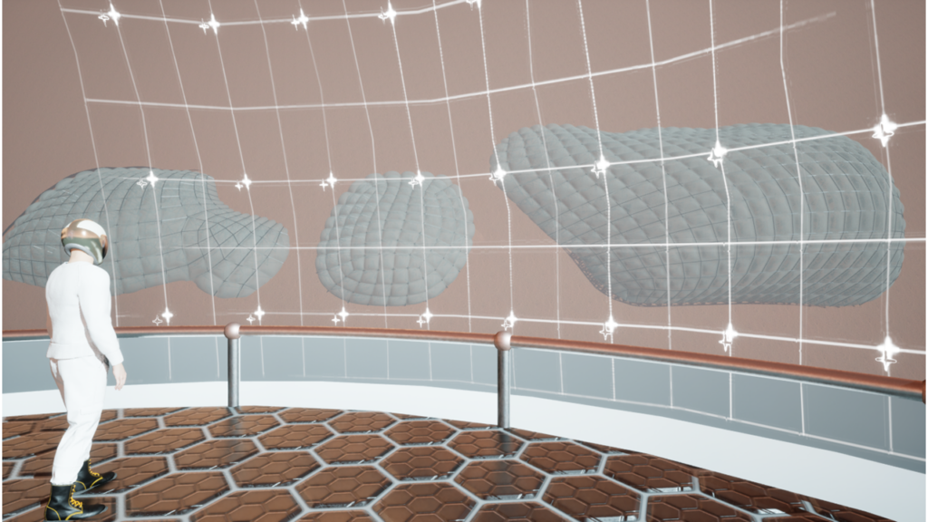
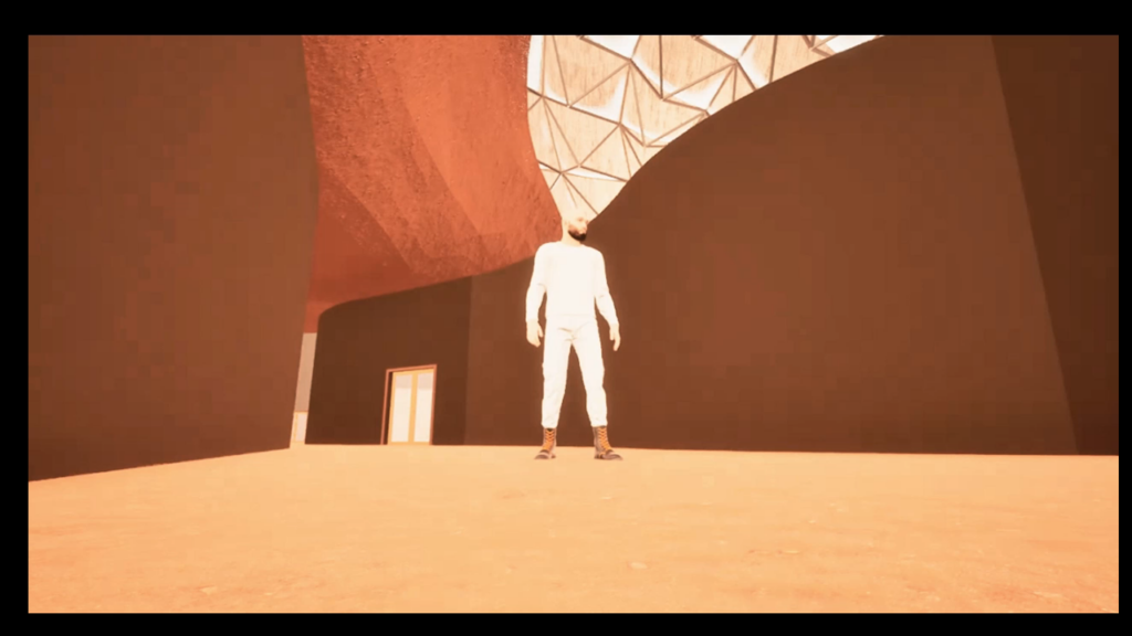
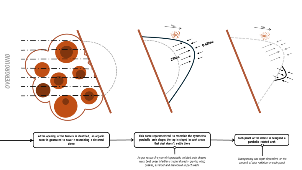
At the openings of these caves, an organic cover is generated resembling a dome, which is reparametrized to resemble the symmetric parabolic arch shape as they work best under pressure difference as well as martian structural loads and quakes.
Each panel of this inflate is designed as a double inflate of the same shape with transparency and depth depending on the solar radiation
RESEARCH
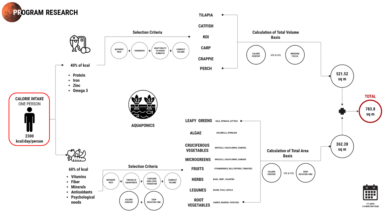
For our Martian Diet of one, we proposed an Aquaponics system. In which we grouped into 2, Protein (40%) and vegetables (60%), after this we applied selection criteria of growing in harsh environments. With all that we got 783.8 sq. m, which symbolizes the amount of space we would need to feed one person of 2300 cal per day in a 171-sol period. With that in mind, for our 1st phase of 50 people, we would need approximately 39 190 sq m for food production.
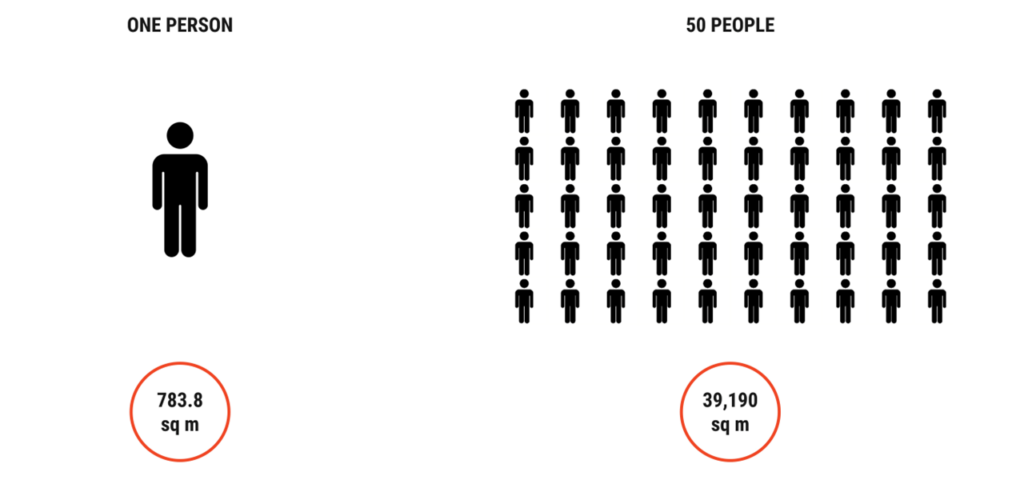
We parametrized all the above information plus we added sq m for living areas based on Mars habitats projects. Thus, creating this chart that indicates how much a single person would need.
On the right side we have the total area for our 3 phases.
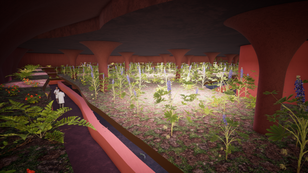
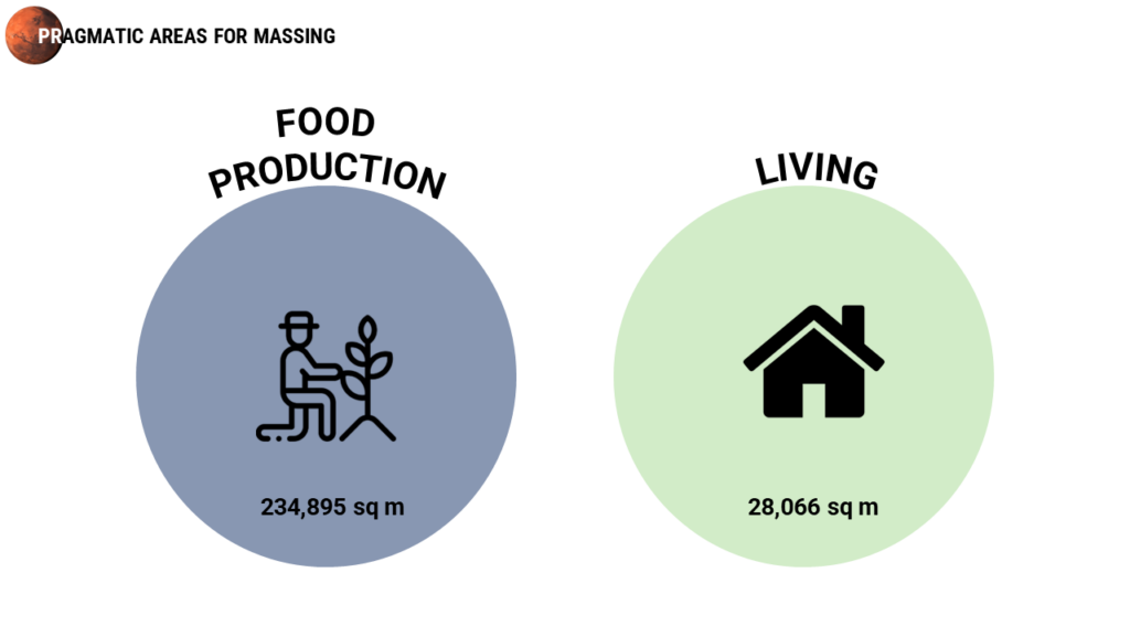
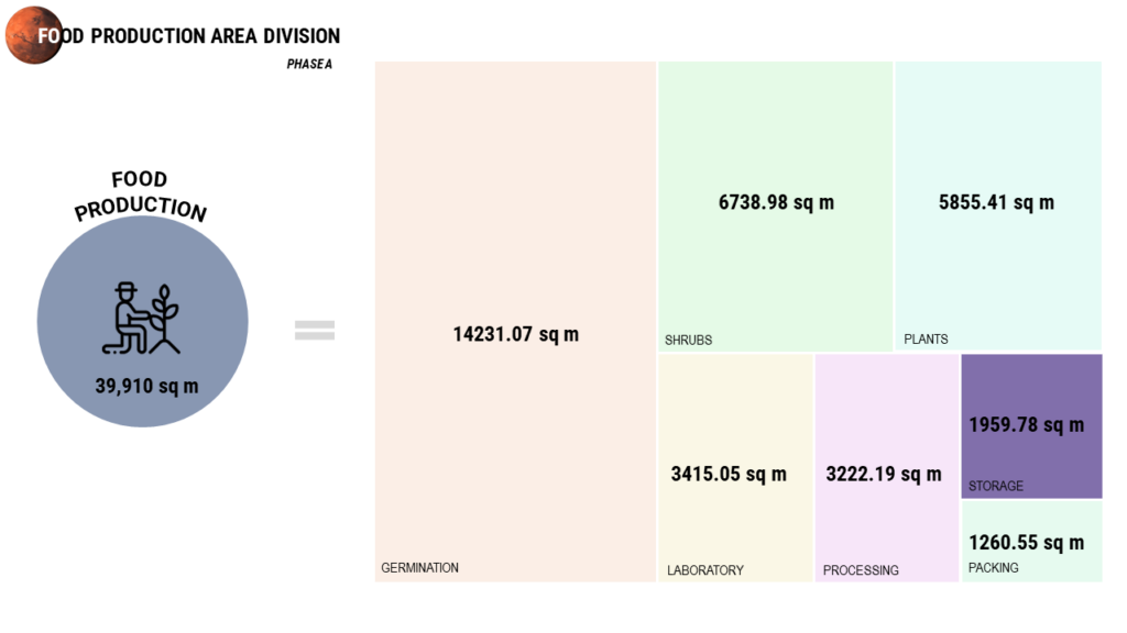
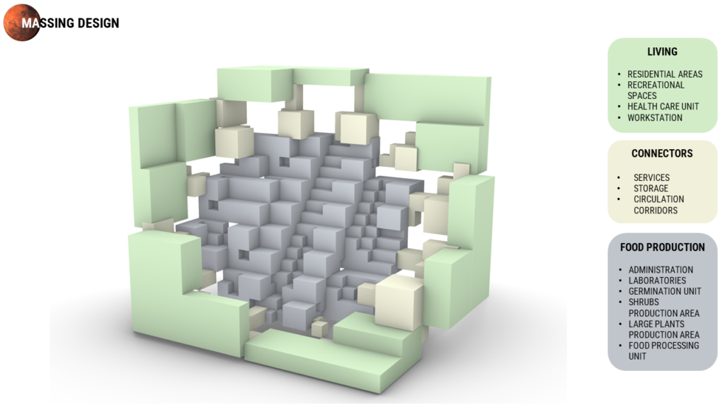
Given the considerable size of the numbers involved, we broadly categorized the areas into food production and living spaces. The food production section encompasses various components such as the Germination Unit, Shrubs Zone, Plants Zone, Laboratory, Processing Areas, Packing, and Storage. Meanwhile, the living units comprise Residential Areas, Recreational Spaces, Health Care Units, and Workstations
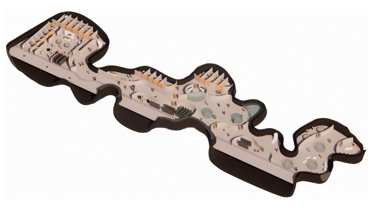
Once we get the designated areas, our next step is to initiate the massing design process. This involves positioning a centrally located underground food production unit to regulate temperature, encircled by living units as subsurface structures. These living units are interconnected with the food production facility through connecting units.
DESIGN DETAILING – COMPUTATIONAL APPROACH
1] UNDERGROUND:
Computationally, Using Elefront, we recreated Martian strata conditions by assigning attributes to voxels. Then, filtering them based on distance from the surface for economics. Next, we integrated our concept of removing the loose soil with our massing design. After finalizing the form, Weaverbird and Dendro are used for mesh smoothing – We then focus on phase A. For the Floor Filtering Process, cross-sections are taken at 2-meter intervals. These sections are sorted based on various usability parameters such as area, height, and shape to determine the final floor plates.
At the end, we import caves as direct shape and floor with level into Revit with added floor component.
2] OVERGROUND:
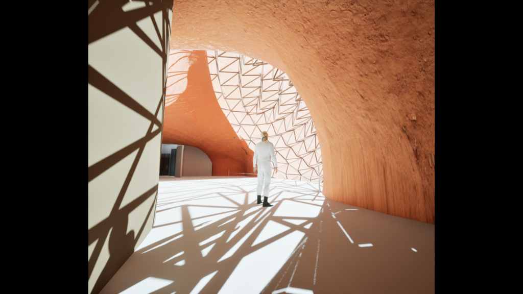
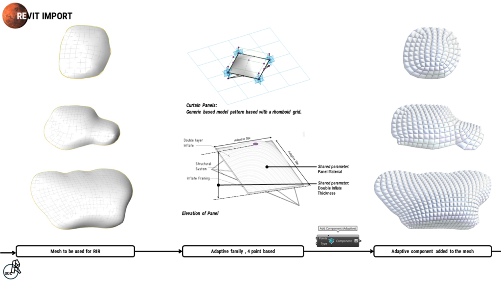
For the overground, we created this shell like skin by extracting the intersection curve with the mountain and did a little offset to ensure that it covers all the edges. Refined the Mesh edges and then used kangaroo to shape it in the paraboloid form that we mentioned earlier.
These Kangaroo generated meshes are imported as base for Rhino inside revit. An adaptive family of double inflate panels were created as a generic model pattern based with a rhombic grid which has the panel material and the depth of the outer inflate as a shared parameter.
This family was then added to the mesh using the add component (adaptive).
PHASES:
Our project is primarily divided into three phases. Phase A (represented by blue color) accommodates the initial 50 Martians. Once these individuals are settled, Phase B (indicated by green color) is initiated, welcoming the next 50 Martians, resulting in a total of 100 people on Mars. Finally, Phase C (denoted by yellow color) marks the arrival of the final 200 people, culminating in a colony of 300 individuals.
ZONNING
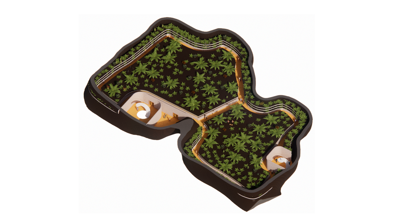
The zoning primarily consists of three zones, as outlined in the massing design: the central food production zone, surrounded by residential areas, and connected by the connector unit. The detailed zoning for Phase A is illustrated in the diagrams below, progressing from left to right. The initial two floors comprise our main living spaces, while subsequent levels will be designated for various food production areas.
DOCUMENTATION
This is a close up of our residential and food production floor plan through Revit,
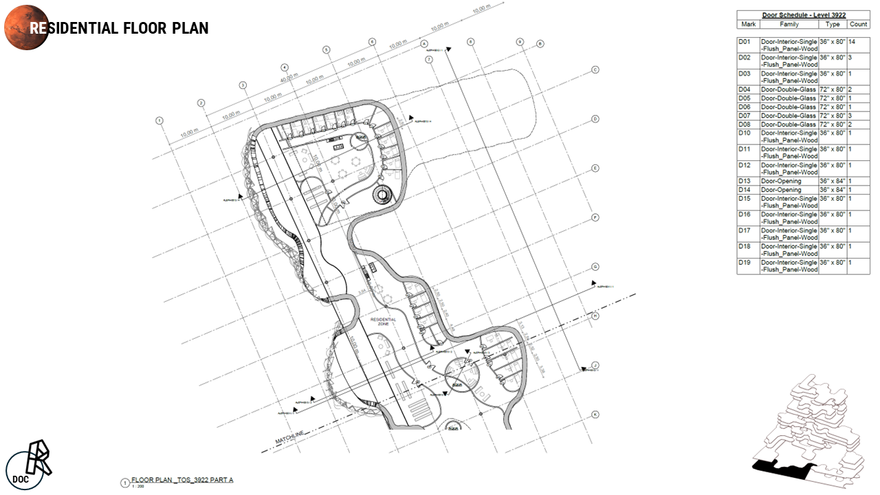

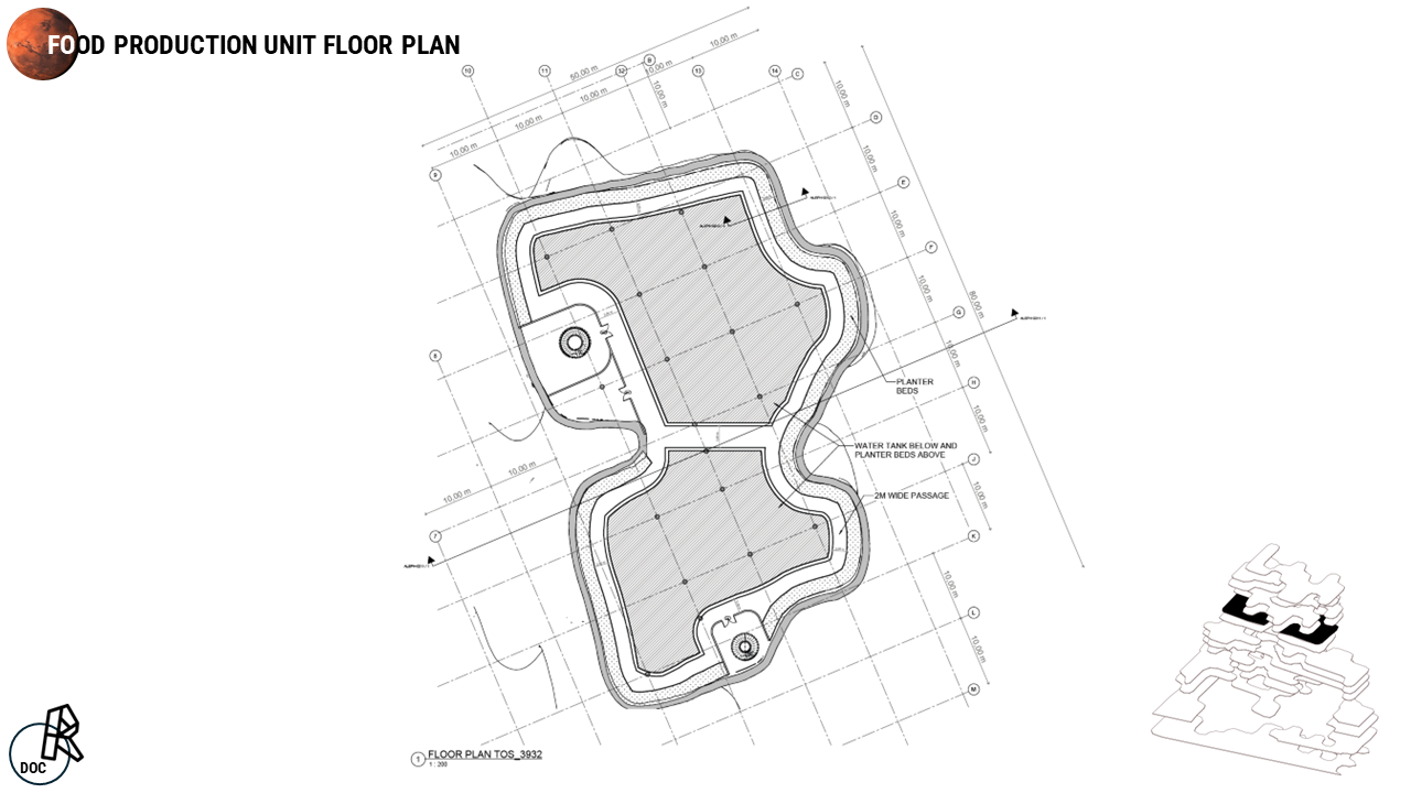
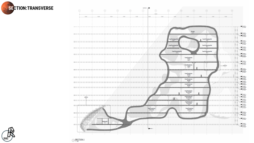
In this section, we observe the segregation of functions across different levels. Showing callouts to highlight specific features.
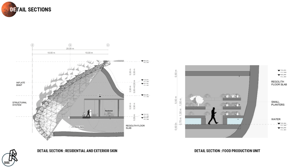
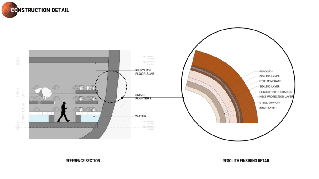
Detailed sections showcase how the outer envelope interacts with the interior. Additionally, they illustrate the various heights of the stacks, crucial for the functioning of the aquaponics system..
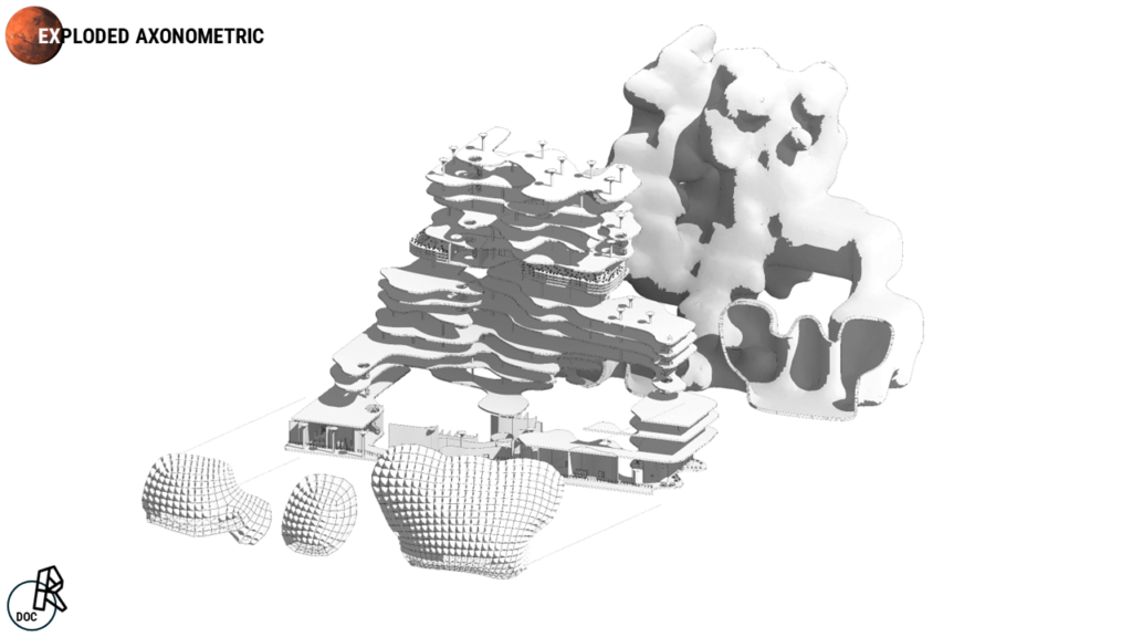
In the Exploded Axonometric view below, we can observe the distinct components of the structure. Beginning with the outer skin of the caves, followed by the floors, structural system, furniture, and concluding with the outer inflates.
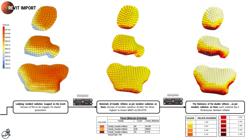
Simultaneously, the incident solar radiation was mapped onto the inflated mesh using Ladybug. Subsequently, these values representing radiation domains were remapped to the element parameters of panel materials, prioritizing from highest to lowest as BNNT, ALON, and ETFE. These materials were further subdivided into panels based on thickness.
This radiation-dependent shared parameter mapping aims to optimize constructability, ensuring that each material has only three thickness options available. The variable height of the outer inflate ranges from 200 to 1000 mm, depending on the radiation levels, while the inner inflate remains fixed at 100 mm.
For treating our regolith walls we have multiple layers sealed together to protect from exterior conditions like a heat protection layer and a thin steel support just to keep things together
For detailed documentation please visit Subterrain Eden’s Dynamic Duo: Revit’s Backbone, Rhino’s Creativity – IAAC BLOG
MATERIALIZATION
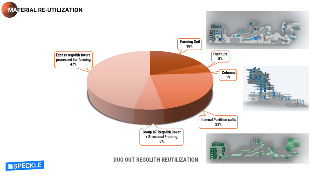
In this chart, we’re illustrating the quantity of regolith we excavated and repurposed for various purposes such as soil for farming, furniture, columns, and walls. Remarkably, we’ve managed to utilize over 50% of the excavated regolith. This achievement was made possible by exploring other groups’ speckle streams and identifying which group was not excavating underground or using regolith for their structural or architectural elements. Specifically, this was identified as group number 07.
CONSTRUCTABILITY
Our journey starts with our arrival, we estimate a 10 sols to get settle, We jump straight into our survey which would consist of have drones mapping the site and indicating where our best place to start digging, our next process is excavation, and to secure a safer space we start building our inflate structures. For this to create a protection for the outside.
Once the inside is secure we start a wall treatment. After that the 3d printer stat their engines and we start creating our interior elements. Once everything is set up we begin adding the farming elements into place. And finally its move in day
SPECKLE STREAM
Next is our speckle stream by importing our model through revit we get some clear visuals by filtering them through levels … material or categories and even filter the floors by their areas
This is our collaborative workflow, which represent what each of us worked on and how we worked circularly, parallelly, or even branch wise using different tools to collaborative and having some major review stages after which we went back and started once again. For us to finally reach our end goal of Revit documentation and visualization of our proposed design.
Check more about the collaborative process on Collaborative Relay – IAAC BLOG
RENDERS